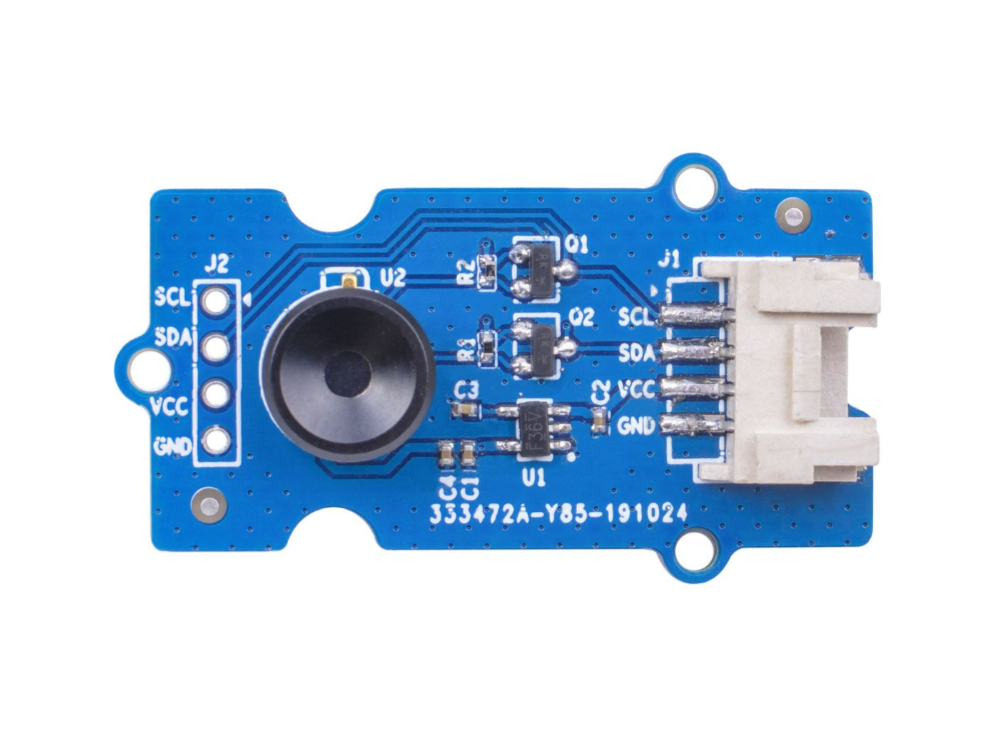
Grove - Thermal Imaging Camera IR-Array MLX90641
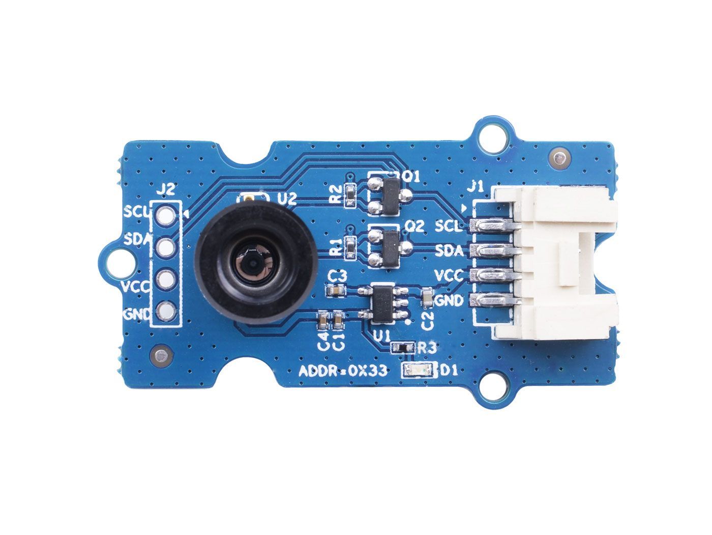
This IR thermal camera carries a 16x12 array of thermal sensors (MLX90641) and it can detect the temperature of objects from far away with a center area accuracy of ±1℃ and average accuracy of ±1.5℃. In order to obtain the thermal images easily, the I2C protocol is used to get the low-resolution images from the camera. The FOV (Field of View) of this camera is 110°x75°, and the temperature measurement range is -40℃ to 300℃. In order to obtain the thermal image easily, I2C protocol is used to get the low-resolution image from the camera.
While Grove - Thermal Imaging Camera is a thermal sensor (MLX90640) , carrying a 32x24 array of thermal sensors, and it can detect the temperature of objects from feet away with the accuracy of ±1.5℃ and can present dynamic thermal images and detect the surrounding temperature from -40℃~300℃. The camera with narrow-angle/wide-angle has an FOV(Field of View) of 55°x35°/110°x75°.In order to obtain the thermal image easily, I2C protocol is used to get the low-resolution image from the camera.
Versions
| Version | Date of Released | Order |
|---|---|---|
| Grove - Thermal Imaging Camera / IR Array MLX90641 110 degree [New] | 03-June-2020 | Buy it |
| Grove - Thermal Imaging Camera / IR Array MLX90640 110 degree | 12-Nov-2019 | Buy it |
This wiki fits both types of the Thermal Imageing Camera IR Array MLX90641 and MLX90640.
Features
- Compact size 16x12 pixel IR thermal sensor array (MLX90641),32x24 array pixel IR thermal sensor array (MLX90640)
- High FOV (field-of-view) of 110°x75° to capture more area
- Wide temperature measurement range (-40℃~300℃)
- I2C Grove interface for easy communication with an MCU
- Fully calibrated IR array for convenient setup
Specification
| Item | Grove - Thermal Imaging Camera - MLX90640 | Grove - Thermal Imaging Camera - MLX90641 |
|---|---|---|
| Thermal sensor | 32X24 array MLX90640 | 16x12 array MLX90641 |
| Operating Voltage | 3.3V - 5V | 3.3V - 5V |
| Current consumption | ~18mA | ~18mA |
| FOV(Field of View) | 110°x75° | 110°x75° |
| Temperature Measurement Range | -40°C - 300°C | -40°C - 300°C |
| Temperature Resolution | ± 1.5°C | ± 1.5°C (±1℃ at center area) |
| Refresh Rate | 0.5Hz - 64Hz | 0.5Hz - 64Hz |
| Interface | I2C Grove interface | I2C Grove interface |
| I2C Address | 0x33 | 0x33 |
Platforms Supported
| Arduino | Raspberry Pi | |||
|---|---|---|---|---|
Getting Started
Getting Started by Wio Terminal
Materials required
| Wio Terminal | Grove - Thermal Imaging Camera / IR Array MLX90641 110 degree |
|---|---|
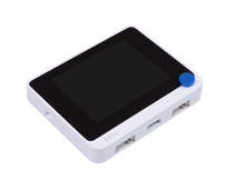 |  |
| Get one now | Get one now |
Hardware Connection
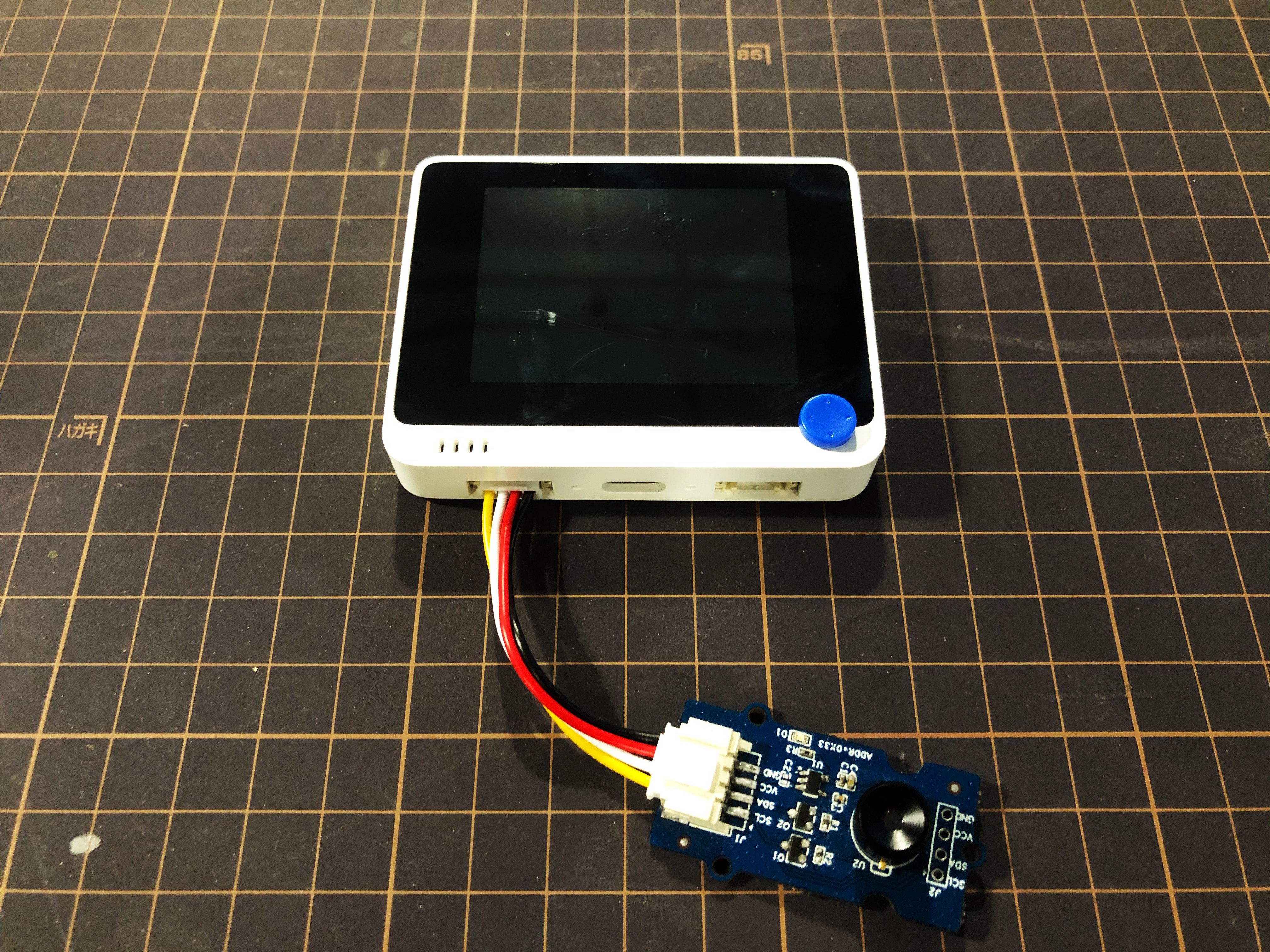
Step 1. Plug Grove - Thermal Imaging Camera to Wio Terminal via Grove cable and also connect Wio Terminal to PC through a USB cable.
Step 2. Download the Library and copy the whole Seeed_Arduino_MLX9064x file and paste it into your Arduino IDE library file.
If it is your first time playing Wio Terminal and not sure which interface to plug on Wio Terminal, please refer to Get Started with Wio Terminal.
Step 3. Copy the Software Code 1 below into your Arduino IDE and upload it for visualization format displayed via Serial Port.
Outcome of Visualization Format
Software Code 1
/*
    Output the temperature readings to all pixels to be read by a Processing visualizer
*/

#include <Wire.h>

#define USE_MLX90641

#ifndef USE_MLX90641
    #include "MLX90640_API.h"
#else
    #include "MLX90641_API.h"
#endif

#include "MLX9064X_I2C_Driver.h"

#if defined(ARDUINO_ARCH_AVR)
    #define debug  Serial

#elif defined(ARDUINO_ARCH_SAMD) ||  defined(ARDUINO_ARCH_SAM)
    #define debug  Serial
#else
    #define debug  Serial
#endif

#ifdef USE_MLX90641
    const byte MLX90641_address = 0x33; //Default 7-bit unshifted address of the MLX90641
    #define TA_SHIFT 8 //Default shift for MLX90641 in open air

    uint16_t eeMLX90641[832];
    float MLX90641To[192];
    uint16_t MLX90641Frame[242];
    paramsMLX90641 MLX90641;
    int errorno = 0;
#else
    const byte MLX90640_address = 0x33; //Default 7-bit unshifted address of the MLX90640

    #define TA_SHIFT 8 //Default shift for MLX90640 in open air

    float mlx90640To[768];
    paramsMLX90640 mlx90640;
#endif
void setup() {
    Wire.begin();
    Wire.setClock(400000); //Increase I2C clock speed to 400kHz

    debug.begin(115200); //Fast debug as possible

    while (!debug); //Wait for user to open terminal
    //debug.println("MLX90640 IR Array Example");


#ifndef USE_MLX90641
    if (isConnected() == false) {
        debug.println("MLX9064x not detected at default I2C address. Please check wiring. Freezing.");
        while (1);
    }
    //Get device parameters - We only have to do this once
    int status;
    uint16_t eeMLX90640[832];
    status = MLX90640_DumpEE(MLX90640_address, eeMLX90640);
    if (status != 0) {
        debug.println("Failed to load system parameters");
    }

    status = MLX90640_ExtractParameters(eeMLX90640, &mlx90640);
    if (status != 0) {
        debug.println("Parameter extraction failed");
    }

    //Once params are extracted, we can release eeMLX90640 array

    //MLX90640_SetRefreshRate(MLX90640_address, 0x02); //Set rate to 2Hz
    MLX90640_SetRefreshRate(MLX90640_address, 0x03); //Set rate to 4Hz
    //MLX90640_SetRefreshRate(MLX90640_address, 0x07); //Set rate to 64H
#else
    if (isConnected() == false) {
        debug.println("MLX90641 not detected at default I2C address. Please check wiring. Freezing.");
        while (1);
    }
    //Get device parameters - We only have to do this once
    int status;
    status = MLX90641_DumpEE(MLX90641_address, eeMLX90641);
    errorno = status;//MLX90641_CheckEEPROMValid(eeMLX90641);//eeMLX90641[10] & 0x0040;//

    if (status != 0) {
        debug.println("Failed to load system parameters");
       while(1);
    }

    status = MLX90641_ExtractParameters(eeMLX90641, &MLX90641);
    //errorno = status;
    if (status != 0) {
        debug.println("Parameter extraction failed");
        while(1);
    }

    //Once params are extracted, we can release eeMLX90641 array

    //MLX90641_SetRefreshRate(MLX90641_address, 0x02); //Set rate to 2Hz
    MLX90641_SetRefreshRate(MLX90641_address, 0x03); //Set rate to 4Hz
    //MLX90641_SetRefreshRate(MLX90641_address, 0x07); //Set rate to 64Hz
#endif

}

void loop() {
#ifndef USE_MLX90641
    long startTime = millis();
    for (byte x = 0 ; x < 2 ; x++) {
        uint16_t mlx90640Frame[834];
        int status = MLX90640_GetFrameData(MLX90640_address, mlx90640Frame);

        float vdd = MLX90640_GetVdd(mlx90640Frame, &mlx90640);
        float Ta = MLX90640_GetTa(mlx90640Frame, &mlx90640);

        float tr = Ta - TA_SHIFT; //Reflected temperature based on the sensor ambient temperature
        float emissivity = 0.95;

        MLX90640_CalculateTo(mlx90640Frame, &mlx90640, emissivity, tr, mlx90640To);
    }
    long stopTime = millis();

    for (int x = 0 ; x < 768 ; x++) {
        //if(x % 8 == 0) debug.println();
        debug.print(mlx90640To[x], 2);
        debug.print(",");
    }
    debug.println("");
#else
    long startTime = millis();

    for (byte x = 0 ; x < 2 ; x++) {
        int status = MLX90641_GetFrameData(MLX90641_address, MLX90641Frame);

        float vdd = MLX90641_GetVdd(MLX90641Frame, &MLX90641);
        float Ta = MLX90641_GetTa(MLX90641Frame, &MLX90641);

        float tr = Ta - TA_SHIFT; //Reflected temperature based on the sensor ambient temperature
        float emissivity = 0.95;

        MLX90641_CalculateTo(MLX90641Frame, &MLX90641, emissivity, tr, MLX90641To);
    }
    long stopTime = millis();
   /*
    debug.print("vdd=");
    debug.print(vdd,2);
    debug.print(",Ta=");
    debug.print(Ta,2);

    debug.print(",errorno=");
    debug.print(errorno,DEC);


    for (int x = 0 ; x < 64 ; x++) {
        debug.print(MLX90641Frame[x], HEX);
        debug.print(",");
    }

    delay(1000);
    */
    for (int x = 0 ; x < 192 ; x++) {
        debug.print(MLX90641To[x], 2);
        debug.print(",");
    }
    debug.println("");
#endif
}

//Returns true if the MLX90640 is detected on the I2C bus
boolean isConnected() {
#ifndef USE_MLX90641
    Wire.beginTransmission((uint8_t)MLX90640_address);
#else
    Wire.beginTransmission((uint8_t)MLX90641_address);
#endif
    if (Wire.endTransmission() != 0) {
        return (false);    //Sensor did not ACK
    }
    return (true);
}
Upload the software code 1 above into your Arduino IDE and open the Serial Port, you will see an outcome of visualization format as following:
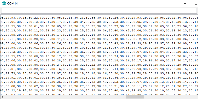
Outcome of Visualization on Wio Terminal
Step 4. Upload the Software Code 2 below into your Arduino IDE for visualization displayed on Wio Terminal.
Software Code 2
#include <Wire.h>
#include "MLX90641_API.h"
#include "MLX9064X_I2C_Driver.h"
#include <TFT_eSPI.h>                // Include the graphics library (this includes the sprite functions)

const byte MLX90641_address = 0x33; //Default 7-bit unshifted address of the MLX90641
#define TA_SHIFT 12 //Default shift for MLX90641 in open air
#define debug  Serial
uint16_t eeMLX90641[832];
float MLX90641To[192];
uint16_t MLX90641Frame[242];
paramsMLX90641 MLX90641;
int errorno = 0;

TFT_eSPI    tft = TFT_eSPI();
TFT_eSprite Display = TFT_eSprite(&tft);  // Create Sprite object "img" with pointer to "tft" object
// the pointer is used by pushSprite() to push it onto the TFT

unsigned long CurTime;

uint16_t TheColor;
// start with some initial colors
uint16_t MinTemp = 25;
uint16_t MaxTemp = 38;

// variables for interpolated colors
byte red, green, blue;

// variables for row/column interpolation
byte i, j, k, row, col, incr;
float intPoint, val, a, b, c, d, ii;
byte aLow, aHigh;

// size of a display "pixel"
byte BoxWidth = 3;
byte BoxHeight = 3;

int x, y;
char buf[20];

// variable to toggle the display grid
int ShowGrid = -1;

// array for the interpolated array
float HDTemp[6400];

void setup() {
    Wire.begin();
    Wire.setClock(2000000); //Increase I2C clock speed to 2M
    debug.begin(115200); //Fast debug as possible

    // start the display and set the background to black

    if (isConnected() == false) {
        debug.println("MLX90641 not detected at default I2C address. Please check wiring. Freezing.");
        while (1);
    }
    //Get device parameters - We only have to do this once
    int status;
    status = MLX90641_DumpEE(MLX90641_address, eeMLX90641);
    errorno = status;//MLX90641_CheckEEPROMValid(eeMLX90641);//eeMLX90641[10] & 0x0040;//

    if (status != 0) {
        debug.println("Failed to load system parameters");
       while(1);
    }

    status = MLX90641_ExtractParameters(eeMLX90641, &MLX90641);
    //errorno = status;
    if (status != 0) {
        debug.println("Parameter extraction failed");
        while(1);
    }

    //Once params are extracted, we can release eeMLX90641 array

    MLX90641_SetRefreshRate(MLX90641_address, 0x05); //Set rate to 16Hz

    tft.begin();
    tft.setRotation(3);
    tft.fillScreen(TFT_BLACK);
    Display.createSprite(TFT_HEIGHT, TFT_WIDTH);
    Display.fillSprite(TFT_BLACK);

    // get the cutoff points for the color interpolation routines
    // note this function called when the temp scale is changed
    Getabcd();

    // draw a legend with the scale that matches the sensors max and min
    DrawLegend();
}
void loop() {
    // draw a large white border for the temperature area
    Display.fillRect(10, 10, 220, 220, TFT_WHITE);
    for (byte x = 0 ; x < 2 ; x++) {
        int status = MLX90641_GetFrameData(MLX90641_address, MLX90641Frame);

        float vdd = MLX90641_GetVdd(MLX90641Frame, &MLX90641);
        float Ta = MLX90641_GetTa(MLX90641Frame, &MLX90641);

        float tr = Ta - TA_SHIFT; //Reflected temperature based on the sensor ambient temperature
        float emissivity = 0.95;

        MLX90641_CalculateTo(MLX90641Frame, &MLX90641, emissivity, tr, MLX90641To);
    }

    interpolate_image(MLX90641To,12,16,HDTemp,80,80);

    //display the 80 x 80 array
    DisplayGradient();

    //Crosshair in the middle of the screen
    Display.drawCircle(115, 115, 5, TFT_WHITE);
    Display.drawFastVLine(115, 105, 20, TFT_WHITE);
    Display.drawFastHLine(105, 115, 20, TFT_WHITE);
    //Displaying the temp at the middle of the Screen

    //Push the Sprite to the screen
    Display.pushSprite(0, 0);

    tft.setRotation(3);
    tft.setTextColor(TFT_WHITE);
    tft.drawFloat(HDTemp[35 * 80 + 35], 2, 90, 20);

}
//Returns true if the MLX90640 is detected on the I2C bus
boolean isConnected() {
    Wire.beginTransmission((uint8_t)MLX90641_address);
    if (Wire.endTransmission() != 0) {
        return (false);    //Sensor did not ACK
    }
    return (true);
}
// function to display the results
void DisplayGradient() {

  tft.setRotation(4);

  // rip through 70 rows
  for (row = 0; row < 70; row ++) {

    // fast way to draw a non-flicker grid--just make every 10 MLX90641To 2x2 as opposed to 3x3
    // drawing lines after the grid will just flicker too much
    if (ShowGrid < 0) {
      BoxWidth = 3;
    }
    else {
      if ((row % 10 == 9) ) {
        BoxWidth = 2;
      }
      else {
        BoxWidth = 3;
      }
    }
    // then rip through each 70 cols
    for (col = 0; col < 70; col++) {

      // fast way to draw a non-flicker grid--just make every 10 MLX90641To 2x2 as opposed to 3x3
      if (ShowGrid < 0) {
        BoxHeight = 3;
      }
      else {
        if ( (col % 10 == 9)) {
          BoxHeight = 2;
        }
        else {
          BoxHeight = 3;
        }
      }
      // finally we can draw each the 70 x 70 points, note the call to get interpolated color
      Display.fillRect((row * 3) + 15, (col * 3) + 15, BoxWidth, BoxHeight, GetColor(HDTemp[row * 80 + col]));
    }
  }

}
// my fast yet effective color interpolation routine
uint16_t GetColor(float val) {

  /*
    pass in value and figure out R G B
    several published ways to do this I basically graphed R G B and developed simple linear equations
    again a 5-6-5 color display will not need accurate temp to R G B color calculation

    equations based on
    http://web-tech.ga-usa.com/2012/05/creating-a-custom-hot-to-cold-temperature-color-gradient-for-use-with-rrdtool/index.html

  */

  red = constrain(255.0 / (c - b) * val - ((b * 255.0) / (c - b)), 0, 255);

  if ((val > MinTemp) & (val < a)) {
    green = constrain(255.0 / (a - MinTemp) * val - (255.0 * MinTemp) / (a - MinTemp), 0, 255);
  }
  else if ((val >= a) & (val <= c)) {
    green = 255;
  }
  else if (val > c) {
    green = constrain(255.0 / (c - d) * val - (d * 255.0) / (c - d), 0, 255);
  }
  else if ((val > d) | (val < a)) {
    green = 0;
  }

  if (val <= b) {
    blue = constrain(255.0 / (a - b) * val - (255.0 * b) / (a - b), 0, 255);
  }
  else if ((val > b) & (val <= d)) {
    blue = 0;
  }
  else if (val > d) {
    blue = constrain(240.0 / (MaxTemp - d) * val - (d * 240.0) / (MaxTemp - d), 0, 240);
  }

  // use the displays color mapping function to get 5-6-5 color palet (R=5 bits, G=6 bits, B-5 bits)
  return Display.color565(red, green, blue);

}

// function to get the cutoff points in the temp vs RGB graph
void Getabcd() {

  a = MinTemp + (MaxTemp - MinTemp) * 0.2121;
  b = MinTemp + (MaxTemp - MinTemp) * 0.3182;
  c = MinTemp + (MaxTemp - MinTemp) * 0.4242;
  d = MinTemp + (MaxTemp - MinTemp) * 0.8182;

}
float get_point(float *p, uint8_t rows, uint8_t cols, int8_t x, int8_t y)
{
    if (x < 0)
    {
        x = 0;
    }
    if (y < 0)
    {
        y = 0;
    }
    if (x >= cols)
    {
        x = cols - 1;
    }
    if (y >= rows)
    {
        y = rows - 1;
    }
    return p[y * cols + x];
}

void set_point(float *p, uint8_t rows, uint8_t cols, int8_t x, int8_t y, float f)
{
    if ((x < 0) || (x >= cols))
    {
        return;
    }
    if ((y < 0) || (y >= rows))
    {
        return;
    }
    p[y * cols + x] = f;
}

// src is a grid src_rows * src_cols
// dest is a pre-allocated grid, dest_rows*dest_cols
void interpolate_image(float *src, uint8_t src_rows, uint8_t src_cols,
                       float *dest, uint8_t dest_rows, uint8_t dest_cols)
{
    float mu_x = (src_cols - 1.0) / (dest_cols - 1.0);
    float mu_y = (src_rows - 1.0) / (dest_rows - 1.0);

    float adj_2d[16]; // matrix for storing adjacents

    for (uint8_t y_idx = 0; y_idx < dest_rows; y_idx++)
    {
        for (uint8_t x_idx = 0; x_idx < dest_cols; x_idx++)
        {
            float x = x_idx * mu_x;
            float y = y_idx * mu_y;
            get_adjacents_2d(src, adj_2d, src_rows, src_cols, x, y);

            float frac_x = x - (int)x; // we only need the ~delta~ between the points
            float frac_y = y - (int)y; // we only need the ~delta~ between the points
            float out = bicubicInterpolate(adj_2d, frac_x, frac_y);
            set_point(dest, dest_rows, dest_cols, x_idx, y_idx, out);
        }
    }
}

// p is a list of 4 points, 2 to the left, 2 to the right
float cubicInterpolate(float p[], float x)
{
    float r = p[1] + (0.5 * x * (p[2] - p[0] + x * (2.0 * p[0] - 5.0 * p[1] + 4.0 * p[2] - p[3] + x * (3.0 * (p[1] - p[2]) + p[3] - p[0]))));
    return r;
}

// p is a 16-point 4x4 array of the 2 rows & columns left/right/above/below
float bicubicInterpolate(float p[], float x, float y)
{
    float arr[4] = {0, 0, 0, 0};
    arr[0] = cubicInterpolate(p + 0, x);
    arr[1] = cubicInterpolate(p + 4, x);
    arr[2] = cubicInterpolate(p + 8, x);
    arr[3] = cubicInterpolate(p + 12, x);
    return cubicInterpolate(arr, y);
}

// src is rows*cols and dest is a 4-point array passed in already allocated!
void get_adjacents_1d(float *src, float *dest, uint8_t rows, uint8_t cols, int8_t x, int8_t y)
{
    // pick two items to the left
    dest[0] = get_point(src, rows, cols, x - 1, y);
    dest[1] = get_point(src, rows, cols, x, y);
    // pick two items to the right
    dest[2] = get_point(src, rows, cols, x + 1, y);
    dest[3] = get_point(src, rows, cols, x + 2, y);
}

// src is rows*cols and dest is a 16-point array passed in already allocated!
void get_adjacents_2d(float *src, float *dest, uint8_t rows, uint8_t cols, int8_t x, int8_t y)
{
    float arr[4];
    for (int8_t delta_y = -1; delta_y < 3; delta_y++)
    {                                          // -1, 0, 1, 2
        float *row = dest + 4 * (delta_y + 1); // index into each chunk of 4
        for (int8_t delta_x = -1; delta_x < 3; delta_x++)
        { // -1, 0, 1, 2
            row[delta_x + 1] = get_point(src, rows, cols, x + delta_x, y + delta_y);
        }
    }
}

// function to draw a legend
void DrawLegend() {

  //color legend with max and min text
  j = 0;

  float inc = (MaxTemp - MinTemp ) / 160.0;

  for (ii = MinTemp; ii < MaxTemp; ii += inc) {
    tft.drawFastHLine(260, 200 - j++, 30, GetColor(ii));
  }

  tft.setTextSize(2);
  tft.setCursor(245, 20);
  tft.setTextColor(TFT_WHITE, TFT_BLACK);
  sprintf(buf, "%2d/%2d", MaxTemp, (int) (MaxTemp * 1.12) + 32);
  tft.print(buf);

  tft.setTextSize(2);
  tft.setCursor(245, 210);
  tft.setTextColor(TFT_WHITE, TFT_BLACK);
  sprintf(buf, "%2d/%2d", MinTemp, (int) (MinTemp * 1.12) + 32);
  tft.print(buf);

}
The outcome of visualization will display on the screen of Wio Terminal if everything goes well
Getting Started by Raspberry Pi
Hardware
Materials required
| Raspberry Pi 4 | Grove Base Hat for Raspberry Pi | Grove - Thermal Imaging Camera / IR Array MLX90641 110 degree |
|---|---|---|
 |  | |
| Get one now | Get one now | Get one now |
Hardware Connection
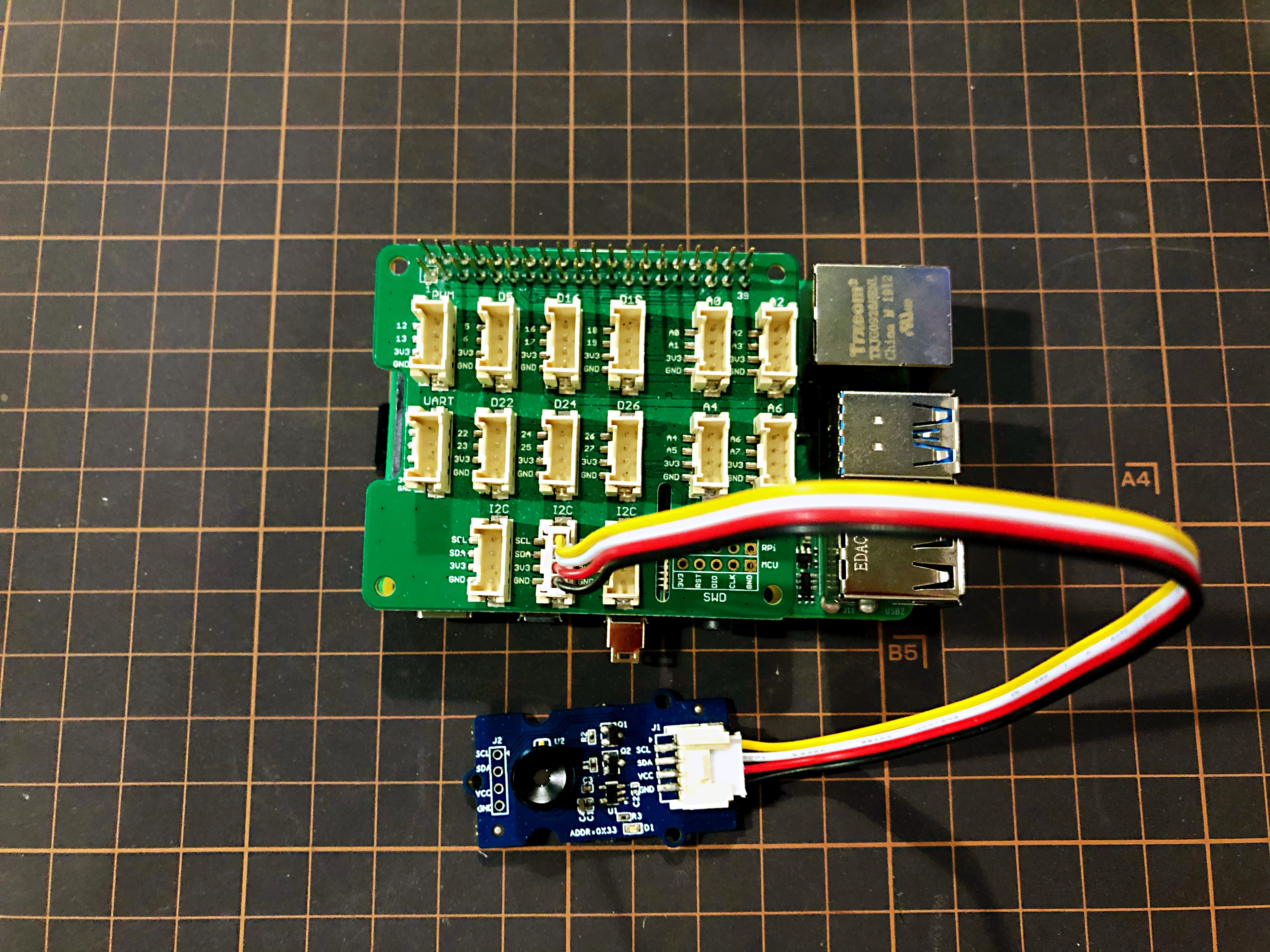
- Step 1 Connect the Grove - Thermal Imaging Camera to one of the two I2C ports.
- Step 2 Plug the Raspberry Pi 4 into Grove Base Hat for Raspberry Pi.
- Step 3 Connect the Raspberry Pi to a display via HDMI cable, and power on the Raspberry Pi 4 by USB type-C.
Software
Raspberry Pi 4 supports Python, so the project demo can be easily displayed from the Raspberry Pi 4 display if you follow the below steps.
- Step 1 Install grove.py by the command
pip3 install Seeed-grove.py
- Step 2 Install the MLX90641 driver with the following command. Python environment(If you don't have authority of your Raspberry Pi):
pip3 install seeed-python-mlx9064x
Upgrade to the latest driver:
pip3 install --upgrade seeed-python-mlx9064x
- Step 3 Check the corresponding i2c number of the Raspberry Pi:
ls /dev/i2c*
You may get the result like this:
/dev/i2c-1
-
Step 4 Download the MLX90641 Library by git clone with command.
-
Step 5 Run the BasicReadings.py file by the following commands:
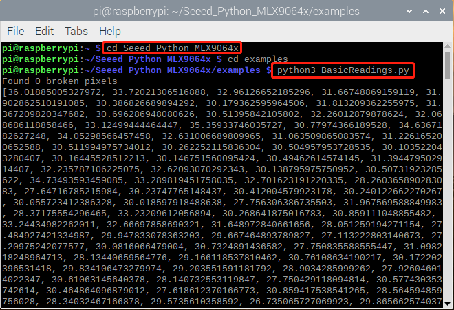
The outcome will be displayed as above if everything goes well.
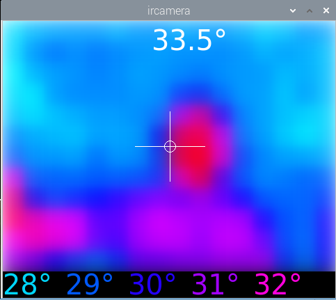
An upgrated UI of outcome on Raspberry Pi has been released as following:
- Step 1 Install pyqt5:
sudo apt-get install python3-pyqt5 -y
- Step 2 Installing from PyPI:
sudo pip3 install seeed_python_ircamera
- Step 3 Set the max i2c speed then reboot:
sudo sh -c "echo dtparam=i2c_arm=on,i2c_arm_baudrate=400000 >> /boot/config.txt"
sudo reboot
- Step 4 Input below command in terminal:
sudo ircamera I2C MLX90641
The outcome will be displayed as following if everything goes well.
Resourse
- [PDF] Datasheet of MLX90641
- [ZIP] MLX90641 Visualization
Tech Support & Product Discussion
Please submit any technical issue into our forum.
Upgradable to Industrial Sensors
With the SenseCAP S2110 controller and S2100 data logger, you can easily turn the Grove into a LoRaWAN® sensor. Seeed not only helps you with prototyping but also offers you the possibility to expand your project with the SenseCAP series of robust industrial sensors.
The IP66 housing, Bluetooth configuration, compatibility with the global LoRaWAN® network, built-in 19 Ah battery, and powerful support from APP make the SenseCAP S210x the best choice for industrial applications. The series includes sensors for soil moisture, air temperature and humidity, light intensity, CO2, EC, and an 8-in-1 weather station. Try the latest SenseCAP S210x for your next successful industrial project.