Grove - I2C High Accuracy Temperature Sensor(MCP9808)

The Grove - I2C High Accuracy Temperature Sensor(MCP9808) is a high accuracy digital module based on MCP9808. Unlike other sensors, you can choose the measurement resolution of this sensor. In addition to high-precision temperature measurements, we also offer programmable temperature alert. We use a separate pin to output the alarm signal, you will find it so convenient to use this signal as an interruption to control other board.
All in all, we believe this sensor will be a new star for temperature control.

Upgradable to Industrial Sensors
With the SenseCAP S2110 controller and S2100 data logger, you can easily turn the Grove into a LoRaWAN® sensor. Seeed not only helps you with prototyping but also offers you the possibility to expand your project with the SenseCAP series of robust industrial sensors.
SenseCAP S210x series industrial sensors provide an out-of-box experience for environmental sensing. Please refer to the S2101 Wireless Temperature and Humidity Sensor with higher performance and robustness for air quality monitoring. The series includes sensors for soil moisture, air temperature and humidity, light intensity, CO2, EC, and an 8-in-1 weather station. Try the latest SenseCAP S210x for your next successful industrial project.
| SenseCAP Industrial Sensor |
 |
| S2101 Air Temp & Humidity |
Features
High Accuracy
- ±0.25 (typical) from -40°C to +125°C
- ±0.5°C (maximum) from -20°C to 100°C
- ±1°C (maximum) from -40°C to +125°C
User-Selectable Measurement Resolution
- +0.5°C, +0.25°C, +0.125°C, +0.0625°C
User-Programmable Temperature Alert Output
I2C interface
Specification
| Item | Value |
|---|---|
| Working voltage | 3.3V/5V |
| Operating range | -40°C to +125°C |
| Digital interface | I2C standard 400 kHz |
| I2C address | 0x18(default)/ 0x18~0x1F(optional) |
Applications
- Industrial Applications
- Industrial Freezers and Refrigerators
- Food Processing
- Personal Computers and Servers
- PC Peripherals
- Consumer Electronics
- Handheld/Portable Devices
Hardware Overview
Pin Map
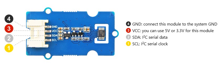
I2C Address
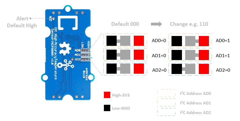
We offer 3 sets of pads on the back of the PCB. The default AD0~AD2 are all connected to the Low level pads, you can cut those pads and solder them to the other side(High level). The I2C address is a 7bits address 0011A0A1A2. 0011 is the address code, which is the factory setting, we can not change it.
A0A1A2 is the slave address, we can change it. The defaut setting is A0=0/A1=0/A2=0, so the default I2C address is 0011000. Normaly the address should be 8bits, so we need to add one bit 0 to the MSB(Most Significant Bit), then we get 0001,1000. This is a binary address, we often use the hexadecimal address in the code, so let's convert the binary address to a hexadecimal address, here we get 0x18. By the same token, if we solder all the pads to the high level, we will get 0001,1111, which is 0x1F. So the I2C address range from 0x18 to 0x1F, among them, you can choose whatever you want, just make sure you will change the I2C address in the file **Seeed_MCP9808.h** in the **Grove_Temperature_sensor_MCP9808-master** library.#define DEFAULT_IIC_ADDR 0X18
Address map
| A2=0 | A0=0 | A0=1 |
|---|---|---|
| A1=0 | A2A1A0-000,0x18 | A2A1A0-001,0x19 |
| A1=1 | A2A1A0-010,0x1A | A2A1A0-011,0x1B |
| A2=1 | A0=0 | A0=1 |
|---|---|---|
| A1=0=0 | A2A1A0-100,0x1C | A2A1A0-101,0x1D |
| A1=0=1 | A2A1A0-110,0x1E | A2A1A0-111,0x1F |
ALE Pad
You can see the ALE Pad on the back of the PCB. The alert signal output from this pad can be used as an external interrupt signal for other controllers. The default output is high, in this board it should be 3.3V. When the condition is met, the output voltage becomes low(0V). You can set the condition when you finish this wiki 😄
Schematic
I2C Address
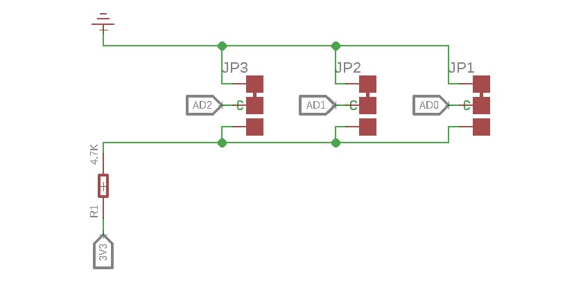
As we mentioned above, we use those three sets of pads to select the I2C address, if you want to change the default adress, you can cut of the wire and re-solder it.
MCP9808
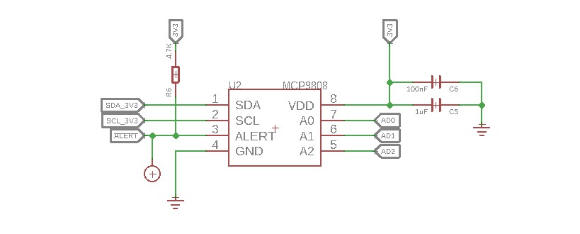
As you can see, the ALE pad is connected to the 3.3V through a pull-up resistor.
Bi-directional level shifter circuit
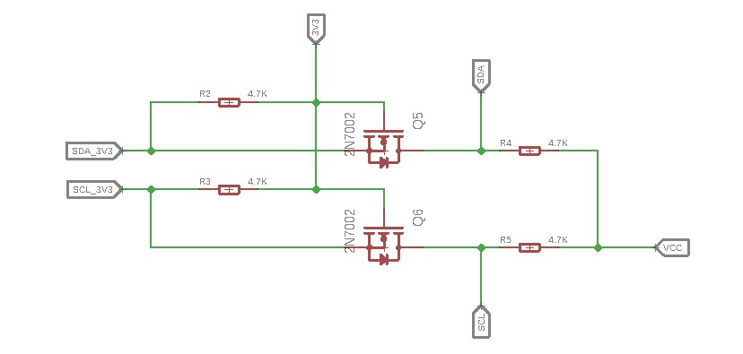
This is a typical Bi-directional level shifter circuit to connect two different voltage section of an I2C bus. The I2C bus of this sensor use 3.3V, if the I2C bus of the Arduino use 5V, this circuit will be needed. In the schematic above, Q6 and Q5 are N-Channel MOSFET 2N7002A, which act as a bidirectional switch. In order to better understand this part, you can refer to the AN10441
In this section we only show you part of the schematic, for the full document please refer to the [Resources](https://wiki.seeedstudio.com/Grove-I2C_High_Accuracy_Temperature_Sensor-MCP9808/#resources)
Platforms Supported
| Arduino | Raspberry Pi | |||
|---|---|---|---|---|
The platforms mentioned above as supported is/are an indication of the module's software or theoritical compatibility. We only provide software library or code examples for Arduino platform in most cases. It is not possible to provide software library / demo code for all possible MCU platforms. Hence, users have to write their own software library.
Getting Started
Play With Arduino
Hardware
Materials required
| Seeeduino V4.2 | Base Shield | Grove - I2C High Accuracy Temperature Sensor |
|---|---|---|
 |  |  |
| Get One Now | Get One Now | Get One Now |
1 Please plug the USB cable gently, otherwise you may damage the port. Please use the USB cable with 4 wires inside, the 2 wires cable can't transfer data. If you are not sure about the wire you have, you can click here to buy
2 Each Grove module comes with a Grove cable when you buy. In case you lose the Grove cable, you can click here to buy.
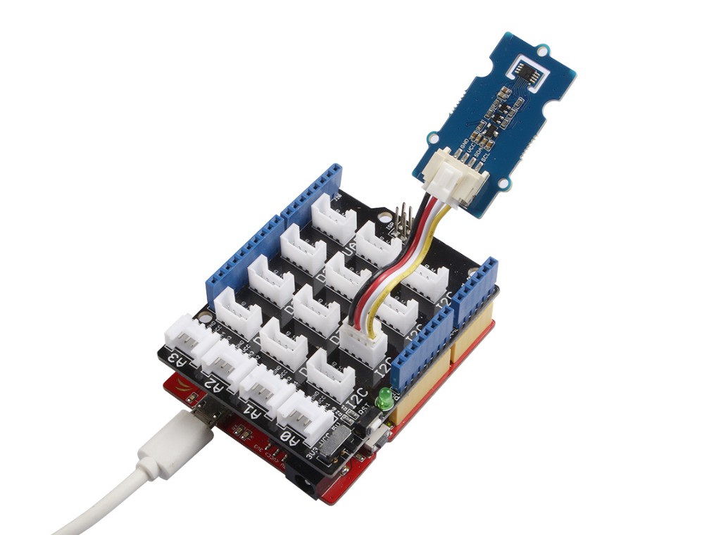
Step 1. Connect the Grove - I2C High Accuracy Temperature Sensor to port I2C of Grove-Base Shield.
Step 2. Plug Grove - Base Shield into Seeeduino.
Step 3. Connect Seeeduino to PC via a USB cable.
If we don't have Grove Base Shield, We also can directly connect this module to Seeeduino as below.
| Seeeduino | Grove-MCP9808 |
|---|---|
| 5V | Red |
| GND | Black |
| SDA | White |
| SCL | Yellow |
Software
If this is the first time you work with Arduino, we strongly recommend you to see [Getting Started with Arduino](https://wiki.seeedstudio.com/Getting_Started_with_Arduino/) before the start.
Step 1. Download the Grove MCP9808 Library from Github.
Step 2. Refer to How to install library to install library for Arduino.
Step 3. Restart the Arduino IDE. Open example via the path: File --> Examples --> Grove Temperature Sensor MCP9808 --> MCP9808_demo_with_limit.
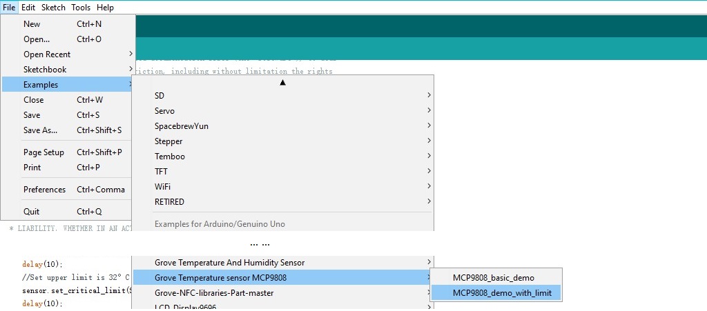
    As shown in the picture above, we provide two demos for you, **MCP9808_basic_demo** and **MCP9808_demo_with_limit**. The **MCP9808_basic_demo** only provide the temperature, the alert fuction is disable.
    And for the **MCP9808_demo_with_limit** demo, the alert function is enable. If you just want the temperature, the basic demo will be fine. If you want to use the alert function, you should choose the limit demo.
Step 4. Upload the demo. If you do not know how to upload the code, please check How to upload code.
Step 5. Open the Serial Monitor of Arduino IDE by click Tool-> Serial Monitor. Or tap the ++ctrl+shift+m++ key at the same time. if every thing goes well, you will get the result.
The result sould be like
sensor init!!
temperature value is: 29.31
temperature value is: 29.31
temperature value is: 29.31
temperature value is: 29.25
temperature value is: 29.25
temperature value is: 29.25
temperature value is: 29.25
temperature value is: 29.25
temperature value is: 29.19
temperature value is: 29.25
Now, let's see how to use the ALE Pad.
The code in the demo MCP9808_demo_with_limit:
#include "Seeed_MCP9808.h"


MCP9808  sensor;

void setup()
{
    Serial.begin(115200);
    if(sensor.init())
    {
        Serial.println("sensor init failed!!");
    }
    //Set upper limit is 30°C
    sensor.set_upper_limit(SET_UPPER_LIMIT_ADDR,0x01e0);
    delay(10);
    //Set upper limit is 32°C
    sensor.set_critical_limit(SET_CRITICAL_LIMIT_ADDR,0x0200);
    delay(10);
    //Enable the alert bit.The alert bit outputs low when the temperature value beyond limit.Otherwise stays high.
    sensor.set_config(SET_CONFIG_ADDR,0x0008);

    Serial.println("sensor init!!");
}


void loop()
{
    float temp=0;
    //Get temperature ,a float-form value.
    sensor.get_temp(&temp);
    Serial.print("temperature value is: ");
    Serial.println(temp);
    delay(1000);
}
In addition to measuring temperature, this code also implements a function. When the temperature is lower than 30℃, the ALE Pad output default high-3.3v. When the temperature is higher than 30℃, the ALE Pad will output low-0v.
So you may ask, what if i want to change the threshold temperature. OK, please come to the line 14:
sensor.set_upper_limit(SET_UPPER_LIMIT_ADDR,0x01e0);
We use this function to control the temperature, the first parameter is the UPPER_LIMIT register address and the second parameter 0x01e0 is the Hexadecimal temperature we set, as we mentioned above, it's 30℃. The 0x01e0 is a four bit Hexadecimal number, the last bit in the right represent the fractional part. We set it as 0, then the valid number is 0x1e. e means 14 in decimal, and the higer bit 1 means 16 in decimal. So 0x1e equals 16+14=30.
We provide 3 functions in the file Seeed_MCP9808.cpp.
sensor.set_upper_limit(SET_UPPER_LIMIT_ADDR,u16);
sensor.set_lower_limit(SET_LOWER_LIMIT_ADDR,u16);
sensor.set_critical_limit(SET_CRITICAL_LIMIT_ADDR,u16);
As we mentioned before, the default output of the ALE Pad is high, and the output level goes low when the temperature meets certain conditions. You can use those 3 functions to set your own conditions.
sensor.set_lower_limit(SET_LOWER_LIMIT_ADDR,u16) is used to set the lower temperature limit, u16 is the 4 bit Hexadecimal temperature we set. When the temperature is lower than the value we set, the output of the ALE Pad will goes down.
sensor.set_upper_limit(SET_UPPER_LIMIT_ADDR,u16) is used to set the upper temperature limit, also u16 is the 4 bit Hexadecimal temperature we set. When the temperature is higher than the value we set, the output of the ALE Pad will goes down.
sensor.set_critical_limit(SET_CRITICAL_LIMIT_ADDR,u16) is used for the inturrupt mode, in this wiki we only show you how to work as a comparator. If you want to know more, please check the datasheet .
Now we can set a condition zone by lower_limit and upper_limit, when the temperature comes to the condition zone, the output will goes low.
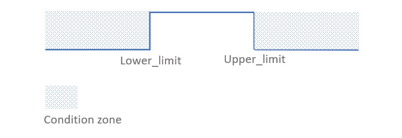
For example, if you want the ALE Pad output high between 28℃ and 30℃, and output low when the tempareture is higer than 30℃ or lower than 28℃. The code should be like:
sensor.set_lower_limit(SET_LOWER_LIMIT_ADDR,0x01c0);
delay(10);
sensor.set_upper_limit(SET_UPPER_LIMIT_ADDR,0x01e0);
delay(10);
Please make sure the **upper_limit** is higer than the **lower_limit**, otherwise it will not output properly. And please make sure the **critical_limit** is higer than the **upper_limit**. A certain delay() is required to ensure that the registers are written correctly.
Play With Raspberry Pi
Hardware
- Step 1. Things used in this project:
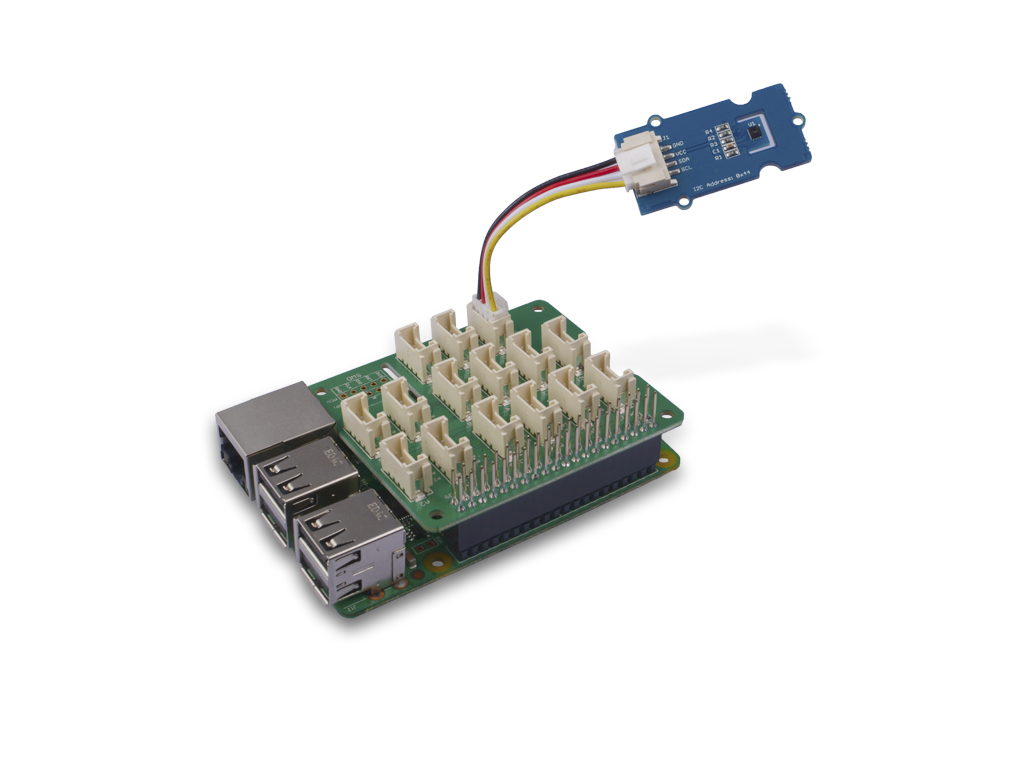
| Raspberry pi | Grove Base Hat for RasPi | Grove - I2C High Accuracy Temperature Sensor |
|---|---|---|
 | 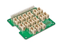 | |
| Get ONE Now | Get ONE Now | Get ONE Now |
- Step 2. Plug the Grove Base Hat into Raspberry.
- Step 3. Connect the Grove - I2C High Accuracy Temperature Sensor to I2C port of the Base Hat.
- Step 4. Connect the Raspberry Pi to PC through USB cable.
Software
If you are using **Raspberry Pi with Raspberrypi OS >= Bullseye**, you have to use this command line **only with Python3**.
- Step 1. Follow Setting Software to configure the development environment.
- Step 2. Download the source file by cloning the grove.py library.
cd ~
git clone https://github.com/Seeed-Studio/grove.py
- Step 3. Excute below commands to run the code.
cd grove.py/grove
python3 grove_high_accuracy_temperature.py
Following is the grove_high_accuracy_temperature.py code.
import sys
import time
from grove.factory import Factory
from grove.temperature import Temper

def main():
    print("Insert Grove - I2C-High-Accuracy-Temperature")
    print("  to Grove-Base-Hat any I2C slot")

    sensor = Factory.getTemper("MCP9808-I2C")
    sensor.resolution(Temper.RES_1_16_CELSIUS)

    print('Detecting temperature...')
    while True:
        print('{} Celsius'.format(sensor.temperature))
        time.sleep(1)


if __name__ == '__main__':
    main()
If everything goes well, you will be able to see the following result
pi@raspberrypi:~/grove.py/grove $ python3 grove_high_accuracy_temperature.py
Insert Grove - I2C-High-Accuracy-Temperature
  to Grove-Base-Hat any I2C slot
Detecting temperature...
24.5 Celsius
24.5 Celsius
24.375 Celsius
^CTraceback (most recent call last):
  File "grove_high_accuracy_temperature.py", line 54, in <module>
    main()
  File "grove_high_accuracy_temperature.py", line 50, in main
    time.sleep(1)
KeyboardInterrupt
You can quit this program by simply press ++ctrl+c++.
Schematic Online Viewer
Resources
- [Zip] Grove - I2C High Accuracy Temperature Sensor(MCP9808) Eagle files
- [Zip] Seeed MCP9808 Library
- [PDF] Datasheet of MCP9808
- [PDF] Datasheet of 2N7002A
- [PDF] AN10441
Project
This is the introduction Video of this product, simple demos, you can have a try.
Tech Support & Product Discussion
Thank you for choosing our products! We are here to provide you with different support to ensure that your experience with our products is as smooth as possible. We offer several communication channels to cater to different preferences and needs.