Grove - I2C Thermocouple Amplifier (MCP9600)
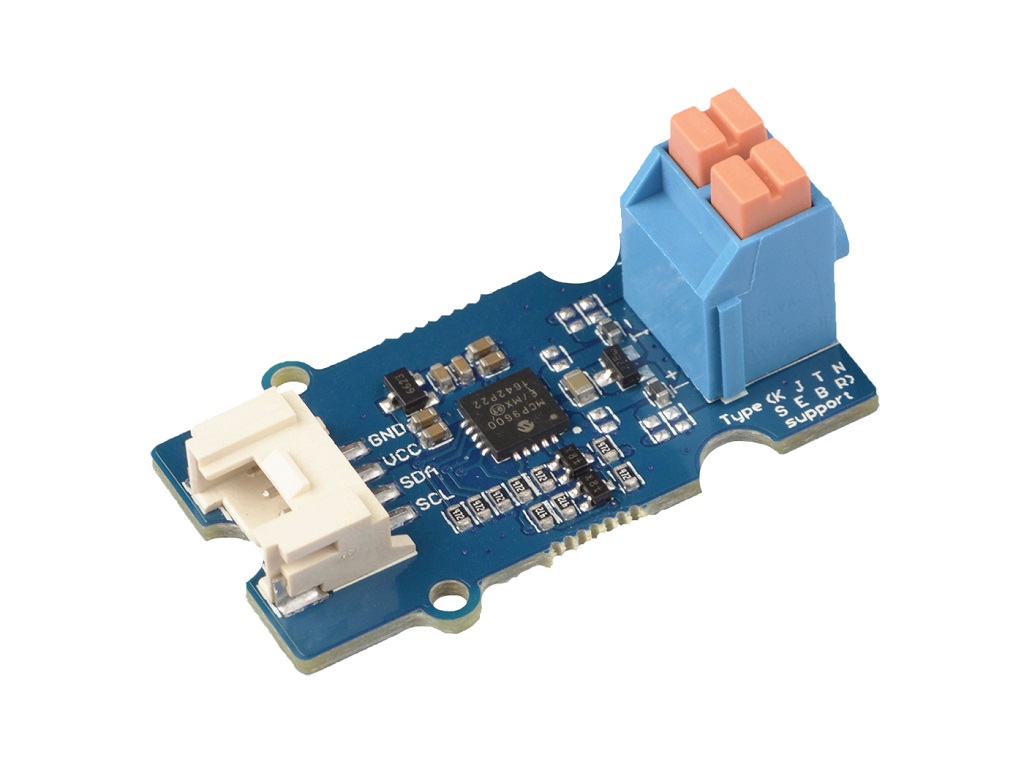
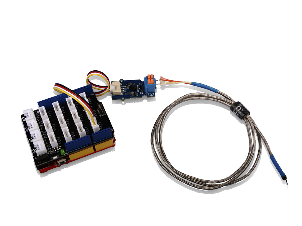
The Grove - I2C Thermocouple Amplifier (MCP9600) is a thermocouple-to-digital converter with integrated cold-junction and I2C communication protocol. This module is designed to be used in conjunction with a k-type thermocouple. The thermocouples have a much larger measurement range than thermistors. For example, this k-type thermocouple on our website has a measurement range of -50℃ to +600℃.
We also provide the alert function for this module, you can use the progarammable alert pin to provide an interrupt signal to the controller.
Again, this module can't work alone, it must work with a k-type thermocouple, if you do not have one, you can consider Thermocouple Temperature Sensor K Type-1M in our bazaar.

Version
| Product Version | Changes | Released Date |
|---|---|---|
| Grove - I2C Thermocouple Amplifier (MCP9600) | Initial | Aug 2018 |
Features
- Integrated Cold-Junction Compensation
- Supported Types (designated by NIST ITS-90): Type K, J, T, N, S, E, B and R
- Four Programmable Temperature Alert Outputs:
- Monitor Hot- or Cold-Junction
- temperatures
- Detect rising or falling temperatures
- Up to 255°C of Programmable Hysteresis
- Programmable Digital Filter for Temperature
- Low Power
The Grove - I2C Thermocouple Amplifier (MCP9600) do support Type K, J, T, N, S, E, B and R on hardware, however, at present, our library do not support any other kind of thermocouple except K type.
Specification
| Item | Value |
|---|---|
| Operating Voltage | 3.3V/5V |
| Ambient Temperature | -40℃ ~ +125℃ |
| Storage Temperature | -65℃ ~ +150℃ |
| Max. Junction Temperature | +150℃ |
| Hot-Junction Accuracy | ±1.5°C (Max.) |
| Measurement Resolution | Hot and Cold-Junctions: 0.0625°C (typical) |
| Interface | I2C |
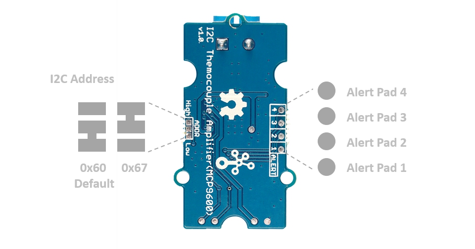
| I2C Address | 0x60(default) / 0x67(optional) |
| Size | L: 40mm W: 20mm H: 18mm |
| Weight | 4.8g |
| Package size | L: 130mm W: 85mm H: 20mm |
| Gross Weight | 11g |
Applications
- Petrochemical Thermal Management
- Hand-Held Measurement Equipment
- Industrial Equipment Thermal Management
- Ovens
- Industrial Engine Thermal Monitor
- Temperature Detection Racks
Hardware Overview
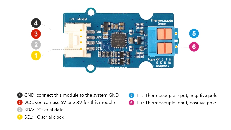
Pin Map
Schematic
Power
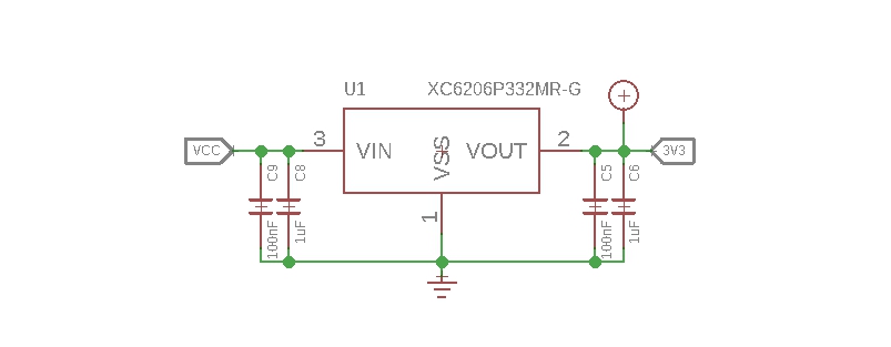
The operating voltage range of MCP9600 is 2.7V ~ 5.5V, we use a power conversion chip XC6206P332MR-G to provide a stable 3.3V for the MCP9600.
Input Jack
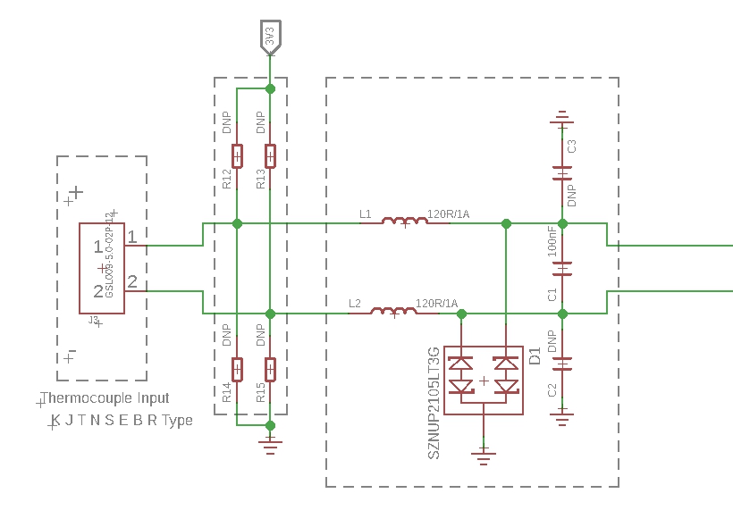
Because of the small signal levels involved, we take a lot measures to filter the noise.
-
1--L1,L2 We use thermocouple up to 1 meter long. Such long wires can be regarded as antennas, which will receive spatial electric field interference and generate high frequency noise. So we use two inductances to filter the high frequency noise.
-
2--C1 It is strongly recommended by the chip manufacturer to add a 100nF ceramic surfacemount differential capacitor, placed across the T+ and T- pins, in order to filter noise on the thermocouple lines.
-
3--D1 We use the SZNUP2105LT3G DUAL BIDIRECTIONAL VOLTAGE SUPPRESSOR to protect this module from ESD(Electro-Static discharge).
Bi-directional level shifter circuit
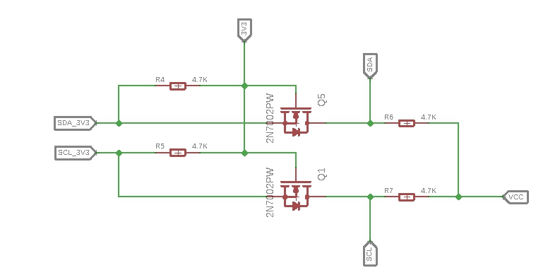
This is a typical Bi-directional level shifter circuit to connect two different voltage section of an I2C bus. The I2C bus of this sensor use 3.3V, if the I2C bus of the Arduino use 5V, this circuit will be needed. In the schematic above, Q1 and Q5 are N-Channel MOSFET 2N7002A, which act as a bidirectional switch. In order to better understand this part, you can refer to the AN10441
Platforms Supported
| Arduino | Raspberry Pi | |||
|---|---|---|---|---|
The platforms mentioned above as supported is/are an indication of the module's software or theoritical compatibility. We only provide software library or code examples for Arduino platform in most cases. It is not possible to provide software library / demo code for all possible MCU platforms. Hence, users have to write their own software library.
Getting Started
Play With Arduino
Hardware
Materials required
| Seeeduino V4.2 | Base Shield | Grove - I2C Thermocouple Amplifier |
|---|---|---|
 |  |  |
| Get One Now | Get One Now | Get One Now |
1 Please plug the USB cable gently, otherwise you may damage the port. Please use the USB cable with 4 wires inside, the 2 wires cable can't transfer data. If you are not sure about the wire you have, you can click here to buy
2 Each Grove module comes with a Grove cable when you buy. In case you lose the Grove cable, you can click here to buy.
-
Step 1. Connect the Grove - I2C Thermocouple Amplifier (MCP9600) to port I2C of Grove-Base Shield.
-
Step 2. Plug Grove - Base Shield into Seeeduino.
-
Step 3. Connect Seeeduino to PC via a USB cable.
If we don't have Grove Base Shield, We also can directly connect this module to Seeeduino as below.
| Seeeduino | Grove Cable | Grove - I2C Thermocouple Amplifier |
|---|---|---|
| GND | Black | GND |
| 5V / 3.3V | Red | VCC |
| SDA | White | SDA |
| SCL | Yellow | SCL |
Software
If this is the first time you work with Arduino, we strongly recommend you to see Getting Started with Arduino before the start.
-
Step 1. Download the Seeed_MCP9600 Library from Github.
-
Step 2. Refer to How to install library to install library for Arduino.
-
Step 3. Restart the Arduino IDE. Open the example, you can open it in the following three ways:
- Open it directly in the Arduino IDE via the path: File --> Examples --> Grove Temperature sensor MCP9600 --> MCP9600_4channel_INT_demo.

- Open it in your computer by click the MCP9600_4channel_INT_demo.ino which you can find in the folder XXXX\Arduino\libraries\Seeed_MCP9600-master\examples\MCP9600_4channel_INT_demo, XXXX is the location you installed the Arduino IDE.

- Or, you can just click the icon
 in upper right corner of the code block to copy the following code into a new sketch in the Arduino IDE.
#include "Seeed_MCP9600.h"

#ifdef ARDUINO_SAMD_VARIANT_COMPLIANCE
  #define SERIAL SerialUSB
#else
  #define SERIAL Serial
#endif

MCP9600 sensor;

/**@brief interruption cfg.
 *
 *
 * */
err_t sensor_INT_config()
{
    err_t ret=NO_ERROR;
    CHECK_RESULT(ret,sensor.set_filt_coefficients(FILT_MID));

    for(int i=0;i<4;i++)
    {
        /*Conver temp num to 16bit data*/
        CHECK_RESULT(ret,sensor.set_alert_limit(i,sensor.covert_temp_to_reg_form(28+i)));
        /*Set hysteresis.for example,set hysteresis to 2℃,when the INT limitation is 30℃,interruption will be generated when
        the temp ecceed limitation,and the interruption flag will stay unless the temp below 30-2(limitation-hysteresis) 28℃. */
        CHECK_RESULT(ret,sensor.set_alert_hys(i,2));

         /*Set when interruption generated the pin's status*/
        CHECK_RESULT(ret,sensor.set_alert_bit(i,ACTIVE_LOW));

        CHECK_RESULT(ret,sensor.clear_int_flag(i));

        /*default is comparator mode*/
        CHECK_RESULT(ret,sensor.set_alert_mode_bit(i,COMPARE_MODE));

        /*Set alert pin ENABLE.*/
        CHECK_RESULT(ret,sensor.set_alert_enable(i,ENABLE));


    }

    /*device cfg*/
    CHECK_RESULT(ret,sensor.set_cold_junc_resolution(COLD_JUNC_RESOLUTION_0_25));
    CHECK_RESULT(ret,sensor.set_ADC_meas_resolution(ADC_14BIT_RESOLUTION));
    CHECK_RESULT(ret,sensor.set_burst_mode_samp(BURST_32_SAMPLE));
    CHECK_RESULT(ret,sensor.set_sensor_mode(NORMAL_OPERATION));

    return NO_ERROR;
}


err_t get_temperature(float *value)
{
    err_t ret=NO_ERROR;
    float hot_junc=0;
    float junc_delta=0;
    float cold_junc=0;
    bool stat=true;

    CHECK_RESULT(ret,sensor.check_data_update(&stat));
    if(stat)
    {
        CHECK_RESULT(ret,sensor.read_hot_junc(&hot_junc));
        CHECK_RESULT(ret,sensor.read_junc_temp_delta(&junc_delta));

        CHECK_RESULT(ret,sensor.read_cold_junc(&cold_junc));

        *value=hot_junc;
    }
    else
    {
        SERIAL.println("data not ready!!");
    }

    return NO_ERROR;
}


void setup()
{
    SERIAL.begin(115200);
    delay(10);
    SERIAL.println("serial start!!");
    if(sensor.init(THER_TYPE_K))
    {
        SERIAL.println("sensor init failed!!");
    }
    sensor_INT_config();
}


void loop()
{
    float temp=0;
    u8 byte=0;
    u8 stat=0;


    get_temperature(&temp);
    SERIAL.print("temperature ==============================>>");
    SERIAL.println(temp);

    sensor.read_INT_stat(&stat);

    SERIAL.println(" ");
    SERIAL.println(" ");

    delay(1000);
}
There are 2 demos in the library:
MCP9600_basic_demo.ino
This example is a sample use of temperature sensor,you need to polling for data.
MCP9600_4channel_INT_demo.ino
here are four alert pads on the sensor module which connect to alert pin.You can set temperature limits by calling the API we provided.The alert pin outputs low when the temperature value beyond limit.You can attach alert pin to a interrupt pin of host,To improve the efficiency of program operation.
-
Step 4. Upload the demo. If you do not know how to upload the code, please check How to upload code.
-
Step 5. Open the Serial Monitor of Arduino IDE by click Tool-> Serial Monitor. Or tap the ++ctrl+shift+m++ key at the same time. Set the baud rate to 115200.
If every thing goes well, when you open the Serial Monitor, you will see the temperature value and the alert information.
serial start!!
version =4011

temperature ==============================>>25.81


temperature ==============================>>27.62


temperature ==============================>>29.37
channel 0generate interruption!!!
channel 1generate interruption!!!


temperature ==============================>>30.81
channel 0generate interruption!!!
channel 1generate interruption!!!
channel 2generate interruption!!!


temperature ==============================>>31.56
channel 0generate interruption!!!
channel 1generate interruption!!!
channel 2generate interruption!!!
channel 3generate interruption!!!


temperature ==============================>>28.56
channel 0generate interruption!!!
channel 1generate interruption!!!
channel 2generate interruption!!!


temperature ==============================>>27.33
channel 0generate interruption!!!
channel 1generate interruption!!!


temperature ==============================>>26.71
channel 0generate interruption!!!
Alert Function

As you can see, there is a hysteresis when the temperature rises and the temperature drops trigger an interrupt. e.g., when the temperature rises, when it reaches 28℃, the alert pin0 will trigger, and when the temperature drops, the limit point becomes 26℃. Only when the temperature become lower than 26 ℃, the alert pin0 will release.
hysteresis= 28℃-26℃ = 2℃
Alert pin 1, alert pin2 and alert pin3 follow the same principle. You can change the hysteresis value and the limit by modify the line 23 and line 26.
CHECK_RESULT(ret,sensor.set_alert_limit(i,sensor.covert_temp_to_reg_form(28+i)));

/*Set hysteresis.for example,set hysteresis to 2℃,when the INT limitation is 30℃,interruption will be generated when
the temp ecceed limitation,and the interruption flag will stay unless the temp below 30-2(limitation-hysteresis) 28℃. */

CHECK_RESULT(ret,sensor.set_alert_hys(i,2));
Use the parameter i to choose the alert pin number, and parameter 28 is the limit value, as for hysteresis, we use the function sensor.set_alert_hys(i,2). The parameter 2 is the hysteresis value.
Schematic Online Viewer
Resources
-
[Zip] Grove - I2C Thermocouple Amplifier (MCP9600) Eagle Files
-
[Zip] Seeed MCP9600 Library
-
[PDF] Datasheet of MCP9600
Project
This is the introduction Video of this product, simple demos, you can have a try.
Tech Support & Product Discussion
Upgradable to Industrial Sensors
With the SenseCAP S2110 controller and S2100 data logger, you can easily turn the Grove into a LoRaWAN® sensor. Seeed not only helps you with prototyping but also offers you the possibility to expand your project with the SenseCAP series of robust industrial sensors.
The IP66 housing, Bluetooth configuration, compatibility with the global LoRaWAN® network, built-in 19 Ah battery, and powerful support from APP make the SenseCAP S210x the best choice for industrial applications. The series includes sensors for soil moisture, air temperature and humidity, light intensity, CO2, EC, and an 8-in-1 weather station. Try the latest SenseCAP S210x for your next successful industrial project.