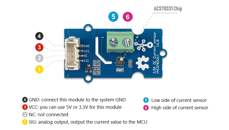
Grove - 2.5A DC Current Sensor(ACS70331)

The Grove - 2.5A DC Current Sensor(ACS70331) is a high precision DC current sensor based on ACS70331. The ACS70331 is a chip series, this module uses ACS70331EESATR-2P5U3, which is Allegro’s high sensitivity,current sensor IC for <2.5 A current sensing applications. It incorporates giant magneto-resistive (GMR) technology that is 25 times more sensitive than traditional Hall-effect sensors to sense the magnetic field generated by the current flowing through the low resistance, integrated primary conductor.
The Grove - 2.5A DC Current Sensor(ACS70331) can measure the DC current up to 2.5A and has a base sensitivity of 800mV/A. This sensor do not support AC current, if you want to measure the AC load please check the:
Grove - 2.5A DC Current Sensor (ACS725)

Feature
- 1 MHz bandwidth with response time <550 ns
- Low noise: 8 mA(rms) at 1 MHz
- 1.1 mΩ primary conductor resistance results in low power loss
- High DC PSRR enables use with low accuracy power supplies or batteries (3 to 4.5 V operation)
- Analog output
Specification
| Parameter | Value |
|---|---|
| Supply voltage | 3.3V / 5V |
| Operating ambient temperature | -40 – 85℃ |
| Storage temperature | - 65°C – 125°C |
| Working Voltage | <100V |
| Current sensing range | 0 – 2.5A |
| Sensitivity | 800mV/A(Typ.) |
| Output interface | Analog |
| Input interface | Screw terminal |
Working Principle
There are two types of current sensing: direct and indirect. Classification is mainly based on the technology used to measure current.
Direct sensing:
- Ohm's Law
Indirect seneing:
- Faraday's Law of Induction
- Magnetic field sensors
- Faraday Effect
The Grove - 2.5A DC Current Sensor(ACS70331) uses magnetic field sensors technology. And there are three kinds of Magnetic field sensors technology:
- Hall effect
- Flux gate sensors
- Magneto-resistive current sensor
The Grove - 2.5A DC Current Sensor(ACS70331) is based on the Magneto-resistive current sensor priciple, which is also known as GMR. A magneto-resistor (MR) is a two terminal device which changes its resistance parabolically with applied magnetic field. This variation of the resistance of MR due to the magnetic field is known as the Magnetoresistive Effect.
The internal construction of the ACS70331 QFN package is shown in Figure 2. The die sits above the primary current path such that magnetic field is produced in plane with the GMR elements on the die. GMR elements 1 and 2 sense field in the +X direction for positive IP current flow, and GMR elements 3 and 4 sense field in the –X direction for positive IP current flow. This enables differential measurement of the current and rejection of external stray fields.

The four GMR elements are arranged in a Wheatstone bridge configuration as shown in Figure 2 such that the output of the bridge is proportional to the differential field sensed by the four elements, rejecting common fields.

Hardware Overview
Platforms Supported
| Arduino | Raspberry Pi | |||
|---|---|---|---|---|
Getting Started
The human body is forbidden to touch the module during the test, otherwise there is danger of electric shock.
Play With Arduino
Materials required
| Seeeduino V4.2 | Base Shield | 2.5A DC Current Sensor(ACS70331) |
|---|---|---|
 |  |  |
| Get ONE Now | Get ONE Now | Get ONE Now |
In addition, you can consider our new Seeeduino Lotus M0+, which is equivalent to the combination of Seeeduino V4.2 and Baseshield.
1 Please plug the USB cable gently, otherwise you may damage the port. Please use the USB cable with 4 wires inside, the 2 wires cable can't transfer data. If you are not sure about the wire you have, you can click here to buy
2 Each Grove module comes with a Grove cable when you buy. In case you lose the Grove cable, you can click here to buy.
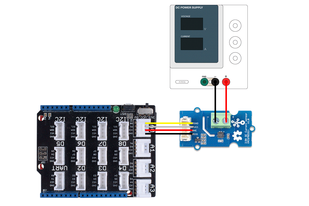
Hardware Connection
Step 1. Connect the Grove - 2.5A DC Current Sensor(ACS70331) to the A0 port of the Base Shield.
Step 2. Connect the positive and negative poles of the circuit to be tested to the corresponding positive and negative poles of the screw terminal.
If you reverse the positive and negative poles, the reading will be reversed. This sensor need calibration before use, so please do not power on the circuit first.
Step 3. Plug Grove - Base Shield into Seeeduino.
Step 4. Connect Seeeduino to PC via a USB cable.
Software
If this is the first time you work with Arduino, we strongly recommend you to see Getting Started with Arduino before the start.
Step 1. Download the Grove Current Sensor Library from Github.
Step 2. In the /example/ folder, you can find the demo code. Here we take the Grove_2_5A_Current_Sensor.ino for instance. Just click the Grove_2_5A_Current_Sensor.ino to open the demo. Or you can copy the following code:
#ifdef ARDUINO_SAMD_VARIANT_COMPLIANCE
#define RefVal 3.3
#define SERIAL SerialUSB
#else
#define RefVal 5.0
#define SERIAL Serial
#endif
//An OLED Display is required here
//use pin A0
#define Pin A0
// Take the average of 10 times
const int averageValue = 10;
int sensorValue = 0;
float sensitivity = 1000.0 / 800.0; //1000mA per 800mV
float Vref = 265; //Firstly,change this!!!
void setup()
{
SERIAL.begin(9600);
}
void loop()
{
// Read the value 10 times:
for (int i = 0; i < averageValue; i++)
{
sensorValue += analogRead(Pin);
// wait 2 milliseconds before the next loop
delay(2);
}
sensorValue = sensorValue / averageValue;
// The on-board ADC is 10-bits
// Different power supply will lead to different reference sources
// example: 2^10 = 1024 -> 5V / 1024 ~= 4.88mV
// unitValue= 5.0 / 1024.0*1000 ;
float unitValue= RefVal / 1024.0*1000 ;
float voltage = unitValue * sensorValue;
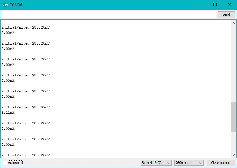
//When no load,Vref=initialValue
SERIAL.print("initialValue: ");
SERIAL.print(voltage);
SERIAL.println("mV");
// Calculate the corresponding current
float current = (voltage - Vref) * sensitivity;
// Print display voltage (mV)
// This voltage is the pin voltage corresponding to the current
/*
voltage = unitValue * sensorValue-Vref;
SERIAL.print(voltage);
SERIAL.println("mV");
*/
// Print display current (mA)
SERIAL.print(current);
SERIAL.println("mA");
SERIAL.print("\n");
// Reset the sensorValue for the next reading
sensorValue = 0;
// Read it once per second
delay(1000);
}
Step 3. Upload the demo. If you do not know how to upload the code, please check How to upload code.
Step 4. Open the Serial Monitor of Arduino IDE by click Tool-> Serial Monitor. Or tap the ++ctrl+shift+m++ key at the same time. Set the baud rate to 9600.
Step 5. Calibration
When there is no current flowing, the sensor will still have a small output value. We call this value zero offset.
Due to the presence of zero offset, the sensor will also have a reading when there is no current. So we set a parameter Vref to fix it, you can find it in the code block above.
Line 21:
float Vref = 265;
//Vref is zero drift value, you need to change this value to the value you actually measured before using it.
In the demo code, we set the Vref to 265, however, the zero offset value varies from board to board. As you know, the board we use in this demo is 288.09. So let's modify the Line 21:
float Vref = 283.20;
Then save the code and upload the code again, follow the Step 2. and Step 3. Now let's see:
When the current output becomes to 0mA or a small value, you have completed the calibration.
- Step 5. Now it's all yours, you can power up the current. Please feel free to use it, remember this is a 2.5A DC Current Sensor, current cannot exceed 2.5A!
If you want to know the calculation formula of the result, please refer to the FAQ Q1
Play with Raspberry
Materials required
| Raspberry pi | Grove Base Hat for RasPi | 2.5A DC Current Sensor |
|---|---|---|
 | 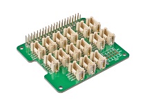 | |
| Get ONE Now | Get ONE Now | Get ONE Now |
Hardware Connection
Step 1. Plug the Grove Base Hat into Raspberry Pi.
Step 2. Connect the Grove - 2.5A DC Current Sensor(ACS70331) to port A0 of the Base Hat.
Step 3. Connect the positive and negative poles of the circuit to be tested to the corresponding positive and negative poles of the screw terminal.
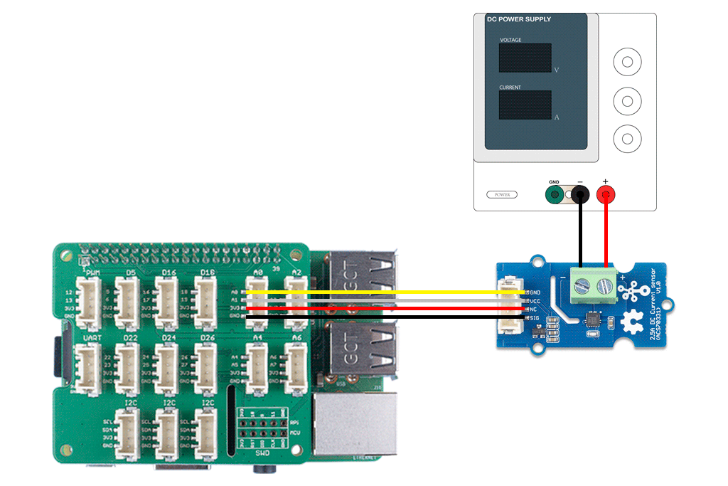
If you reverse the positive and negative poles, the reading will be reversed. This sensor need calibration before use, so please do not power on the circuit first.
- Step 4. Power the Raspberry Pi via the Micro-USB cable.
You can power the Raspberry Pi by computer USB port or DC adapter, however, if you are using the Raspberry pi 3B+, we strongly recommend you to power it by DC adapter, if you use the USB port of the PC, you may damage the Raspberry Pi 3B+.
Software
Step 1. Follow Setting Software to configure the development environment.
Step 2. Download the source file by cloning the grove.py library.
cd ~
git clone https://github.com/Seeed-Studio/grove.py
- Step 3. Excute following commands to run the code.
cd grove.py/grove   # to enter the demo file folder
python grove_current_sensor.py 0 2.5A   # to run the demo program
Then the terminal will output as following:
pi@raspberrypi:~/grove.py/grove $ python grove_current_sensor.py 0 2.5A
pin_voltage(mV):
270
current(mA):
13.0
()
pin_voltage(mV):
270
current(mA):
13.0
()
pin_voltage(mV):
270
current(mA):
13.0
()
pin_voltage(mV):
269
current(mA):
11.0
()
pin_voltage(mV):
270
current(mA):
13.0
()
^CTraceback (most recent call last):
  File "grove_current_sensor.py", line 200, in <module>
    main()
  File "grove_current_sensor.py", line 185, in main
    time.sleep(1)
KeyboardInterrupt
Tap ctrl+c+ to quit.
Please note the second command, There are two parameters after the file name:
- 0 means the sensor is connected to port A0. If you connect the sensor to port A2, then you need to change this parameter to 2. This parameter has a range of 0-7, but if you use the Grove base hat, you can only use 0/2/4/6 because of the physical limitations of the interface.
- 2.5A means the current sensor type is 2.5A DC
| Sensor | Current type | Parameter Value |
|---|---|---|
| Grove - 2.5A DC Current Sensor(ACS70331) | DC | 2.5A |
| Grove - 2.5A DC Current Sensor (ACS725) | DC | 5A_DC |
| AC | 5A_AC | |
| Grove - 10A DC Current Sensor (ACS725) | DC | 10A |
Please note that the DC current sensor of 2.5A will have a large error when measuring a small range, so it is recommended that you provide a current of more than 200mA for testing. In addition, the measurement environment will affect the accuracy, such as the supply voltage ripple to be as small as possible.
Step 4 Calibration.
When there is no current flowing, the sensor will still have a small output value. We call this value zero offset. As you can see, in the step 3, the zero offset of this board is 270mV, converted into current is 13mA.
Due to the presence of zero offset, the sensor will also have a reading when there is no current. So we set a parameter Vref to fix it, you can find it in the python grove_current_sensor.py. For the Grove - 2.5A DC Current Sensor(ACS70331), we set the Vref to 260 by default, however the zero offset varies from board to board. That's why we need to do the calibration first.
Check the python code below:
#!/usr/bin/env python
# -*- coding: utf-8 -*-
#
# The MIT License (MIT)
# Copyright (C) 2018  Seeed Technology Co.,Ltd.
#
# This is the library for Grove Base Hat
# which used to connect grove sensors for Raspberry Pi.
'''
This is the code for
    - `Grove - 2.5A DC current sensor  <https://www.seeedstudio.com/Grove-2-5A-DC-Current-Sensor-ACS70331-p-2929.html>`_
    - `Grove - 5A AC/DC current sensor <https://www.seeedstudio.com/Grove-5A-DC-AC-Current-Sensor-ACS70331-p-2928.html>`_
    - `Grove - 10A current sensor      <https://www.seeedstudio.com/Grove-10A-DC-Current-Sensor-ACS725-p-2927.html>`_
Examples:
    .. code-block:: python
        import time
        from grove_current_sensor import Current
        pin = 0
        sensor_type = "2.5A"
        #if use 10A current sensor input: pin = 0 , sensor_type = "10A"
        if (sensor_type == "2.5A"):
            sensitivity = 1000.0 / 800.0
            Vref = 260
        if (sensor_type == "5A_DC"):
            sensitivity = 1000.0 / 200.0
            Vref = 1498
        if (sensor_type == "5A_AC"):
            sensitivity = 1000.0 / 200.0
            Vref = 1498
        if (sensor_type == "10A"):
            sensitivity = 1000.0 / 264.0
            Vref = 322
        averageValue = 500
        ADC = Current()
        while True:
            if(sensor_type == "5A_AC"):
                pin_voltage = ADC.get_nchan_vol_milli_data(pin,averageValue)
                current = ADC.get_nchan_AC_current_data(pin,sensitivity,Vref,averageValue)
            else:
                temp = ADC.get_nchan_current_data(pin,sensitivity,Vref,averageValue)
                current = temp[0]
                pin_voltage = temp[1]

            current = round(current)
            print("pin_voltage(mV):")
            print(pin_voltage)
            print("current(mA):")
            print(current)
            print()
            time.sleep(1)

'''

import sys
import time
from grove.i2c import Bus

ADC_DEFAULT_IIC_ADDR = 0X04

ADC_CHAN_NUM = 8

REG_RAW_DATA_START = 0X10
REG_VOL_START = 0X20
REG_RTO_START = 0X30

REG_SET_ADDR = 0XC0

__all__ = ['Current','Bus']

class Current():
    '''
    Grove Current Sensor class
    '''

    def __init__(self,bus_num=1,addr=ADC_DEFAULT_IIC_ADDR):
        '''
        Init iic.
        Args:
            bus_num(int): the bus number;
            addr(int): iic address;
        '''
        self.bus = Bus(bus_num)
        self.addr = addr

    def get_nchan_vol_milli_data(self,n,averageValue):
        '''
        Get n chanel data with unit mV.
        :param int n: the adc pin.
        :param int averageValue: Average acquisition frequency.
        Returns:
            int: voltage value
        '''
        val = 0
        for i in range(averageValue):
            data = self.bus.read_i2c_block_data(self.addr,REG_VOL_START+n,2)
            val += data[1]<<8|data[0]
        val = val / averageValue
        return val

    def get_nchan_current_data(self,n,sensitivity,Vref,averageValue):
        '''
        2.5A/5A DC/10A cunrrent sensor get n chanel data with unit mA.
        :param int n: the adc pin.
        :param float sensitivity: The coefficient by which voltage is converted into current.
        :param int Vref: Initial voltage at no load.
        :param int averageValue: Average acquisition frequency.
        Returns:
            int: current value
        '''
        val = 0
        for i in range(averageValue):
            data = self.bus.read_i2c_block_data(self.addr,REG_VOL_START+n,2)
            val += data[1]<<8|data[0]
        val = val / averageValue
        currentVal = (val - Vref) * sensitivity
        return currentVal,val

    def get_nchan_AC_current_data(self,n,sensitivity,Vref,averageValue):
        '''
        5A current sensor AC output and get n chanel data with unit mA.
        :param int n: the adc pin.
        :param float sensitivity: The coefficient by which voltage is converted into current.
        :param int Vref: Initial voltage at no load.
        :param int averageValue: Average acquisition frequency.
        Returns:
            int: current value
        '''
        sensorValue = 0
        for i in range(averageValue):
            data=self.bus.read_i2c_block_data(self.addr,REG_VOL_START+n,2)
            val=data[1]<<8|data[0]
            if(val > sensorValue):
                sensorValue=val
            time.sleep(0.00004)
        currentVal = ((sensorValue - Vref) * sensitivity)*0.707
        return currentVal

ADC = Current()
def main():
    if(len(sys.argv) == 3):

        pin = int(sys.argv[1])
        sensor_type = sys.argv[2]
        if (pin < 8 and (sensor_type == "2.5A" or sensor_type == "5A_DC" or sensor_type == "5A_AC" or sensor_type == "10A") ):
            if (sensor_type == "2.5A"):
                sensitivity = 1000.0 / 800.0
                Vref = 260
            if (sensor_type == "5A_DC"):
                sensitivity = 1000.0 / 200.0
                Vref = 1498
            if (sensor_type == "5A_AC"):
                sensitivity = 1000.0 / 200.0
                Vref = 1498
            if (sensor_type == "10A"):
                sensitivity = 1000.0 / 264.0
                Vref = 322
            averageValue = 500

            while True:

                if(sensor_type == "5A_AC"):
                    pin_voltage = ADC.get_nchan_vol_milli_data(pin,averageValue)
                    current = ADC.get_nchan_AC_current_data(pin,sensitivity,Vref,averageValue)
                else:
                    temp = ADC.get_nchan_current_data(pin,sensitivity,Vref,averageValue)
                    current = temp[0]
                    pin_voltage = temp[1]

                current = round(current)
                print("pin_voltage(mV):")
                print(pin_voltage)
                print("current(mA):")
                print(current)
                print()
                time.sleep(1)

        else:
            print("parameter input error!")
            print("Please enter parameters for example: python grove_current_sensor 0 2.5A")
            print("parameter1: 0-7")
            print("parameter2: 2.5A/5A_DC/5A_AC/10A")

    else:
        print("Please enter parameters for example: python grove_current_sensor 0 2.5A")
        print("parameter1: 0-7")
        print("parameter2: 2.5A/5A_DC/5A_AC/10A")


if __name__ == '__main__':
    main()
You can modify the Vref at line 147 of the code block above:
        if (pin < 8 and (sensor_type == "2.5A" or sensor_type == "5A_DC" or sensor_type == "5A_AC" or sensor_type == "10A") ):
            if (sensor_type == "2.5A"):
                sensitivity = 1000.0 / 800.0
                Vref = 260
            if (sensor_type == "5A_DC"):
                sensitivity = 1000.0 / 200.0
                Vref = 1498
            if (sensor_type == "5A_AC"):
                sensitivity = 1000.0 / 200.0
                Vref = 1498
            if (sensor_type == "10A"):
                sensitivity = 1000.0 / 264.0
                Vref = 322
            averageValue = 500
As you can see, for the 2.5A Current Sensor the default Vref is 260, and in the Step 3, we can find it when there is no current the zero offset value is 270mV. So let's change it into 270.
            if (sensor_type == "2.5A"):
                sensitivity = 1000.0 / 800.0
                Vref = 270
Now, let's run this demo again.
pi@raspberrypi:~/grove.py/grove $ python grove_current_sensor.py 0 2.5A
pin_voltage(mV):
269
current(mA):
-1.0
()
pin_voltage(mV):
270
current(mA):
0.0
()
pin_voltage(mV):
270
current(mA):
0.0
()
pin_voltage(mV):
270
current(mA):
0.0
()
pin_voltage(mV):
270
current(mA):
0.0
()
^CTraceback (most recent call last):
  File "grove_current_sensor.py", line 200, in <module>
    main()
  File "grove_current_sensor.py", line 185, in main
    time.sleep(1)
KeyboardInterrupt
Well, better than before, now you can measure the current more accurately 😄
FAQ
Q1# What's the current calculation formula?
A1: If you think the principle part is very complicated, let's put it in a easy way. The current in the circuit to be tested excites the magnetic field, which causes the resistance value of the GMR elements change. And the resistance change in the bridge causes a change in the voltage at the output of the chip. We call the voltage output as VIOUT.
VIOUT = Sens × Ip + VIOUT(Q)
Sens: Sens is the coefficient that converts the current into an output voltage. For this module it is 800mA/V.
Ip: Ip is the current value in the circuit to be tested, Unit mA.
VIOUT(Q): VIOUT(Q) is the voltage output when the Ip is 0mA(which means there is no current in the circuit to be tested), Unit mV.
Here comes the current value:
Ip = (VIOUT - VIOUT(Q)) / Sens
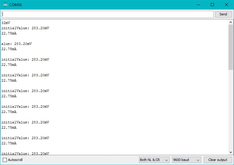
Now, Let's review the figure 5, we will explain why the current value of the output is not 0 when the actual current value in the circuit to be tested is 0. As you can see in the figure 5, the initialValue is 283.20mV, which is the VIOUT; the current is 22.75mA, which is the Ip. As for the VIOUT(Q), it is the Vref we set in the code. In figure 5, it is 265. And the Sens is 800mA/V, which is 800mA/1000mV. Now, just do some math:
{(283.20mV-265mV) / (800mA/1000mV)} = 22.75mA
So, in the figure 6, when we set the Vref to 283.20, the Ip turns to 0mA.
Schematic Online Viewer
Resources
Tech Support & Product Discussion
Thank you for choosing our products! We are here to provide you with different support to ensure that your experience with our products is as smooth as possible. We offer several communication channels to cater to different preferences and needs.