Grove - Electricity Sensor
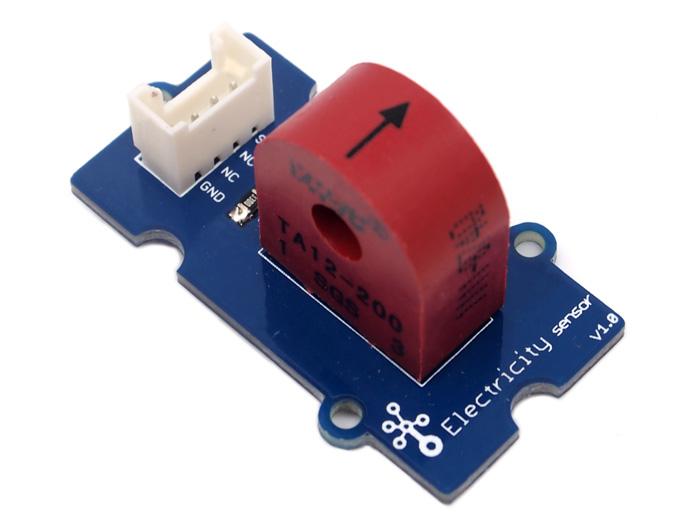
The Electricity sensor module is a member of Grove. It is based on the TA12-200 current transformer which can transform the large AC into small amplitude. You can use it to test large alternating current up to 5A.

Features
- Grove compatible interface
- Maximum 5A input
- High accuracy
- Small size
More details about Grove modules please refer to Grove System
Application Ideas
- Alternating current measurement
- Device condition monitoring
Specification
Key Specification
| Items | Min |
|---|---|
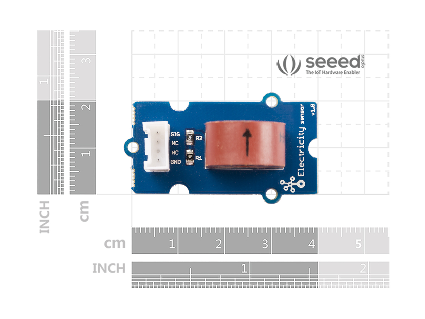
| PCB Size | 2.0cm*4.0cm |
| Interface | 2.0mm pitch pin header |
| IO Structure | SIG,NC,NC,GND |
| RoHS | YES |
Electronic Characteristics
| Items | Min | Norm | Max | Unit |
|---|---|---|---|---|
| Transformation ratio | - | 2000:1 | - | - |
| Input Current | 0 | - | 5 | A |
| Output Current | 0 | - | 2.5 | mA |
| Sampling Resistance | - | 800 | - | Ω |
| Sampling Voltage | 0 | - | 2 | V |
| Working Frequency | 20 | - | 20K | HZ |
| Nonlinear scale | - | - | 0.2% | - |
| Phase Shift | - | - | 5' | - |
| Operating Temperature | -55 | - | 85 | ℃ |
| Dielectric strength | - | 6 | - | KVAC/1min |
Hardware Overview
Platforms Supported
| Arduino | Raspberry Pi | |||
|---|---|---|---|---|
The platforms mentioned above as supported is/are an indication of the module's software or theoritical compatibility. We only provide software library or code examples for Arduino platform in most cases. It is not possible to provide software library / demo code for all possible MCU platforms. Hence, users have to write their own software library.
Getting started
Play with Arduino
The following sketch demonstrates a simple application of measuring the amplitude of the alternating voltage. The SIG pin will output a alternating voltage based on the alternating current being measured. You can measure the value using ADC.
Hardware
- Step 1. Prepare the below stuffs:
| Seeeduino V4.2 | Base Shield | Grove-Electricity_Sensor |
|---|---|---|
 |  |  |
| Get One Now | Get One Now | Get One Now |
- Step 2. Connect Grove-Electricity_Sensor to port A0 of Grove-Base Shield.
- Step 3. Plug Grove - Base Shield into Seeeduino.
- Step 4. Connect Seeeduino to PC via a USB cable.

If we don't have Grove Base Shield, We also can directly connect this module to Seeeduino as below.
| Seeeduino | Grove-Electricity_Sensor |
|---|---|
| 5V | Red |
| GND | Black |
| Not Conencted | White |
| A0 | Yellow |
Software
Step 1. Copy the code and flash it into the controller board and upload the code.
    /****************************************************************************/
    //  Function: Measure the amplitude current of the alternating current and
    //            the effective current of the sinusoidal alternating current.
    //  Hardware: Grove - Electricity Sensor
    //  Date:    Jan 19,2013
    //  by www.seeedstudio.com
    #define ELECTRICITY_SENSOR A0 // Analog input pin that sensor is attached to

    float amplitude_current;               //amplitude current
    float effective_value;       //effective current

    void setup()
    {
        Serial.begin(9600);
        pins_init();
    }
    void loop()
    {
        int sensor_max;
        sensor_max = getMaxValue();
        Serial.print("sensor_max = ");
        Serial.println(sensor_max);
        //the VCC on the Grove interface of the sensor is 5v
        amplitude_current=(float)sensor_max/1024*5/800*2000000;
        effective_value=amplitude_current/1.414;//minimum_current=1/1024*5/800*2000000/1.414=8.6(mA)
                            //Only for sinusoidal alternating current
        Serial.println("The amplitude of the current is(in mA)");
        Serial.println(amplitude_current,1);//Only one number after the decimal point
        Serial.println("The effective value of the current is(in mA)");
        Serial.println(effective_value,1);
    }
    void pins_init()
    {
        pinMode(ELECTRICITY_SENSOR, INPUT);
    }
    /*Function: Sample for 1000ms and get the maximum value from the SIG pin*/
    int getMaxValue()
    {
        int sensorValue;             //value read from the sensor
        int sensorMax = 0;
        uint32_t start_time = millis();
        while((millis()-start_time) < 1000)//sample for 1000ms
        {
            sensorValue = analogRead(ELECTRICITY_SENSOR);
            if (sensorValue > sensorMax)
            {
                /*record the maximum sensor value*/
                sensorMax = sensorValue;
            }
        }
        return sensorMax;
    }
The minimum effective current that can be sensed by the code can be calculated using the equation below. minimum_current=1/10245/8002000000/1.414=8.6(mA).
- Step 2. Open the serial monitor, The results is as follows:

With Raspberry Pi
Hardware
- Step 1. Prepare the below stuffs:
| Raspberry pi | GrovePi_Plus | Grove-Electricity_Sensor |
|---|---|---|
 |  | |
| Get One Now | Get One Now | Get One Now |
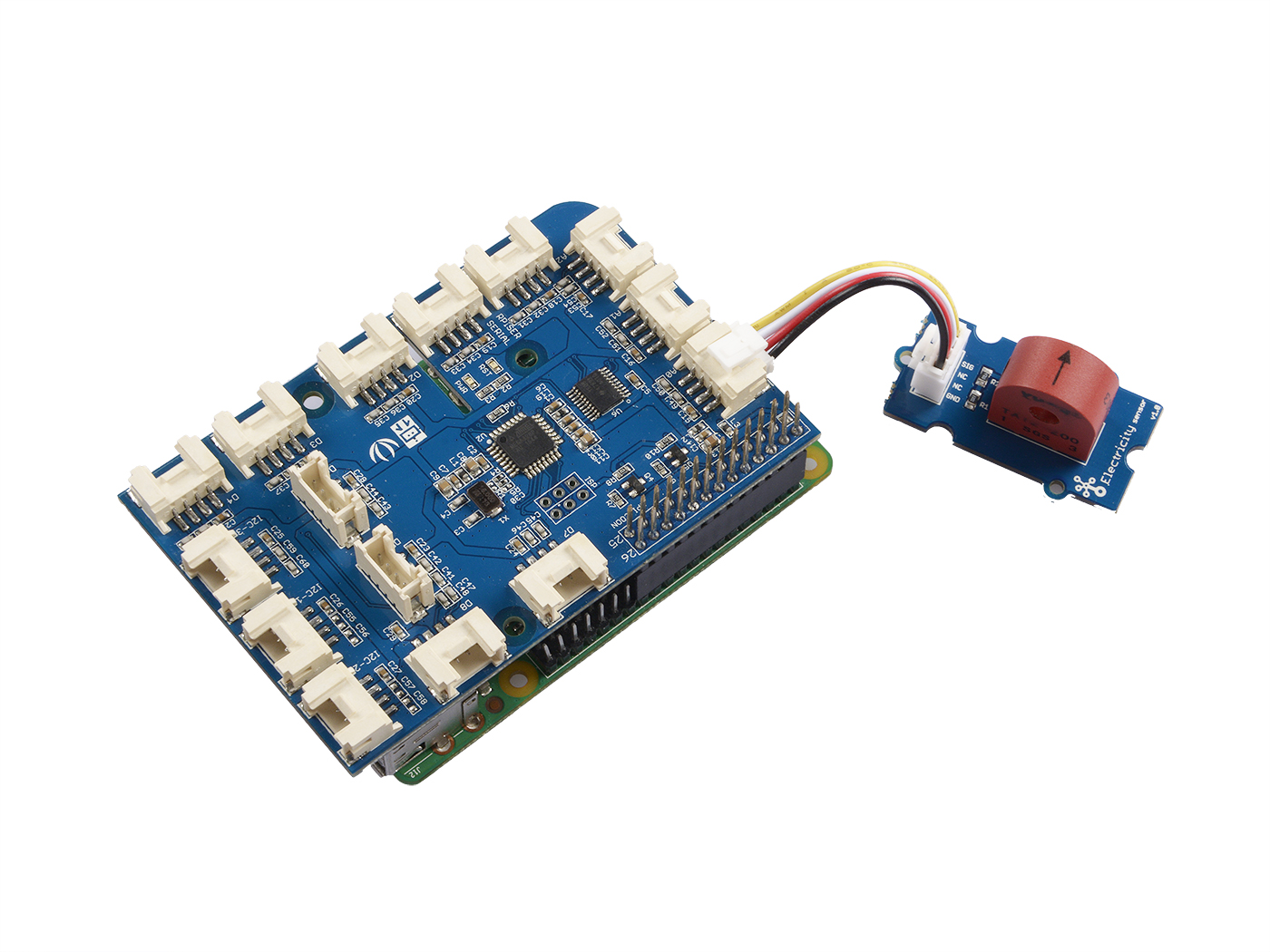
- Step 2. Plug the GrovePi_Plus into Raspberry.
- Step 3. Connect Grove-Electricity_Sensor to A0 port of GrovePi_Plus.
- Step 4. Connect the Raspberry to PC through USB cable.
Software
- Step 1. Follow Setting Software to configure the development environment.
- Step 2. Git clone the Github repository.
cd ~
git clone https://github.com/DexterInd/GrovePi.git
- Step 3. Excute below commands to use this sensor
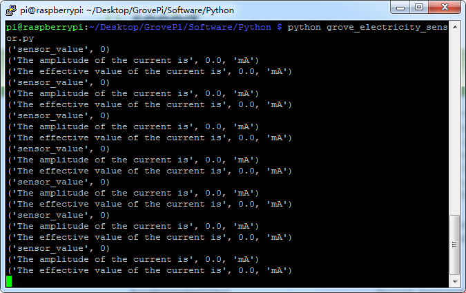
cd ~/GrovePi/Software/Python
python grove_electricity_sensor.py
Here is the code of example:
#!/usr/bin/env python
#
# GrovePi Example for using the Grove Electricity Sensor (https://www.seeedstudio.com/wiki/Grove_-_Electricity_Sensor)
#
# The GrovePi connects the Raspberry Pi and Grove sensors.  You can learn more about GrovePi here:  http://www.dexterindustries.com/GrovePi
#
# Have a question about this example?  Ask on the forums here:  http://forum.dexterindustries.com/c/grovepi
#
'''
## License
The MIT License (MIT)
GrovePi for the Raspberry Pi: an open source platform for connecting Grove Sensors to the Raspberry Pi.
Copyright (C) 2017  Dexter Industries
Permission is hereby granted, free of charge, to any person obtaining a copy
of this software and associated documentation files (the "Software"), to deal
in the Software without restriction, including without limitation the rights
to use, copy, modify, merge, publish, distribute, sublicense, and/or sell
copies of the Software, and to permit persons to whom the Software is
furnished to do so, subject to the following conditions:
The above copyright notice and this permission notice shall be included in
all copies or substantial portions of the Software.
THE SOFTWARE IS PROVIDED "AS IS", WITHOUT WARRANTY OF ANY KIND, EXPRESS OR
IMPLIED, INCLUDING BUT NOT LIMITED TO THE WARRANTIES OF MERCHANTABILITY,
FITNESS FOR A PARTICULAR PURPOSE AND NONINFRINGEMENT. IN NO EVENT SHALL THE
AUTHORS OR COPYRIGHT HOLDERS BE LIABLE FOR ANY CLAIM, DAMAGES OR OTHER
LIABILITY, WHETHER IN AN ACTION OF CONTRACT, TORT OR OTHERWISE, ARISING FROM,
OUT OF OR IN CONNECTION WITH THE SOFTWARE OR THE USE OR OTHER DEALINGS IN
THE SOFTWARE.
'''

import time
import grovepi

# Connect the Grove Electricity Sensor to analog port A0
# SIG,NC,NC,GND
sensor = 0

grovepi.pinMode(sensor,"INPUT")

# Vcc of the grove interface is normally 5v
grove_vcc = 5

while True:
  try:
      # Get sensor value
      sensor_value = grovepi.analogRead(sensor)

      # Calculate amplitude current (mA)
      amplitude_current = (float)(sensor_value / 1024 * grove_vcc / 800 * 2000000)

      # Calculate effective value (mA)
      effective_value = amplitude_current / 1.414

      # minimum_current = 1 / 1024 * grove_vcc / 800 * 2000000 / 1.414 = 8.6(mA)
      # Only for sinusoidal alternating current

      print("sensor_value", sensor_value)
      print("The amplitude of the current is", amplitude_current, "mA")
      print("The effective value of the current is", effective_value, "mA")
      time.sleep(1)

  except IOError:
      print ("Error")
Here is the result.
Schematic Online Viewer
Resources
- [Eagle] Grove -Electricity Sensor Eagle File
- [PDF] Schematic in PDF
Tech Support & Product Discussion
Thank you for choosing our products! We are here to provide you with different support to ensure that your experience with our products is as smooth as possible. We offer several communication channels to cater to different preferences and needs.