Grove - Digital Light Sensor
This module is based on the I2C light-to-digital converter TSL2561 to transform light intensity to a digital signal. Different from traditional analog light sensor, as Grove - Light Sensor, this digital module features a selectable light spectrum range due to its dual light sensitive diodes: infrared and full spectrum.
We can switch among three detection modes to take your readings. They are infrared mode, full spectrum and human visible mode. When running under the human visible mode, this sensor will give you readings just close to your eye feelings.

Version
| Product Version | Changes | Released Date |
|---|---|---|
| Grove - Digital Light Sensor V1.1 | Initial | Oct 2015 |
Upgradable to Industrial Sensors
With the SenseCAP S2110 controller and S2100 data logger, you can easily turn the Grove into a LoRaWAN® sensor. Seeed not only helps you with prototyping but also offers you the possibility to expand your project with the SenseCAP series of robust industrial sensors.
SenseCAP S210x series industrial sensors provide an out-of-box experience for environmental sensing. Please refer to the S2102 Wireless Light Intensity Sensor with higher performance and robustness for light intensity detection. The series includes sensors for soil moisture, air temperature and humidity, light intensity, CO2, EC, and an 8-in-1 weather station. Try the latest SenseCAP S210x for your next successful industrial project.
| SenseCAP Industrial Sensor |
 |
| S2102 Light |
Features
- Selectable detection modes
- High resolution 16-Bit digital output at 400 kHz I2C Fast-Mode
- Wide dynamic range: 0.1 - 40,000 LUX
- Wide operating temperature range: -40°C to 85°C
- Programmable interrupt function with User-Defined Upper and lower threshold settings
- I2C Address 0x29
If you want to use multiplue I2C devices, please refer to Software I2C.
More details about Grove modules please refer to Grove System
Specifications
| Items | Min | Typical | Max | Unit |
|---|---|---|---|---|
| Supply voltage, VDD | 3.3 | 5 | 5.1 | V |
| Operating temperature | -30 | \ | 70 | ℃ |
| SCL,SDA input low voltage | -0.5 | \ | 0.8 | V |
| SCL,SDA input high voltage | 2.3 | \ | 5.1 | V |
Platforms Supported
| Arduino | Raspberry Pi | |||
|---|---|---|---|---|
The platforms mentioned above as supported is/are an indication of the module's software or theoritical compatibility. We only provide software library or code examples for Arduino platform in most cases. It is not possible to provide software library / demo code for all possible MCU platforms. Hence, users have to write their own software library.
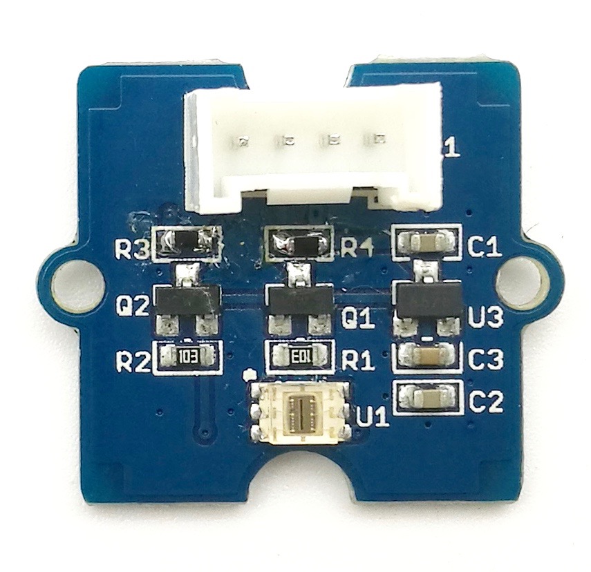
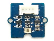
Hardware Overview
U1: TSL2561 IC, Light-To-Digital Converter. Here is the Functional Block Diagram.
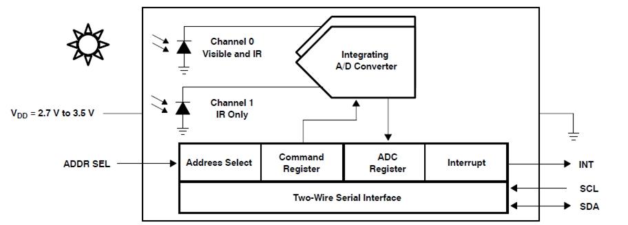
-
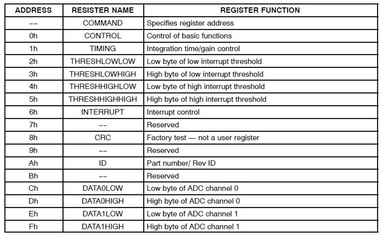
Register Map
The TSL2561 is controlled and monitored by sixteen registers (three are reserved) and a command register accessed through the serial interface. These registers provide for a variety of control functions and can be read to determine results of the ADC conversions. The register set is summarised as shown below.
- Spectrum Response Curve
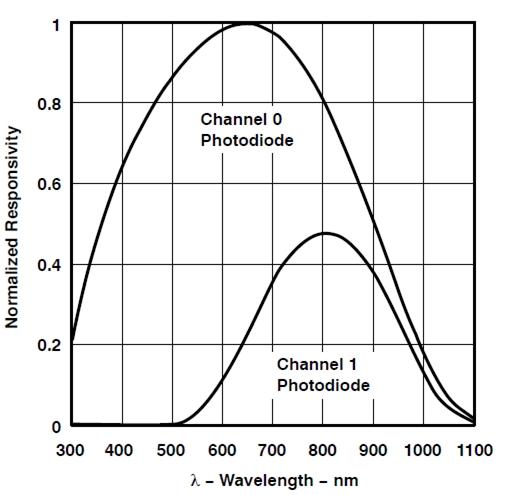
Two channels of the digital light sensor have different response characteristic. That's why you can choose its working mode by having both of them on or one of them off.
U3: XC6206MR332 IC, Positive Voltage Regulators.
Q1,Q2: BSN20 IC, N-channel Enhancement Mode Vertical D-MOS Transistor.
SCL,SDA: I2C Signal Interface
Getting Started
If this is the first time you work with Arduino, we firmly recommend you to see Getting Started with Arduino before the start.
Play With Arduino
Hardware
- Step 1. Prepare the below stuffs:
| Seeeduino V4 | Base Shield | Grove - Digital light sensor |
|---|---|---|
 |  |  |
| Get ONE Now | Get ONE Now | Get ONE Now |
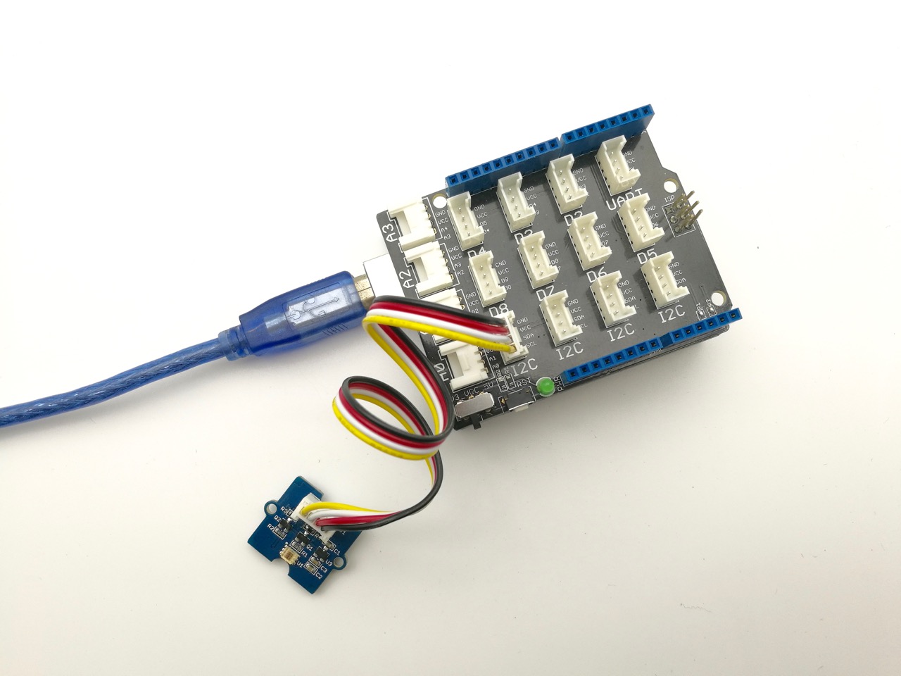
- Step 2. Connect Grove - Digital light Sensor to I2C port of base shield.
- Step 3. Plug the base Shield into Arduino.
- Step 4. Connect Arduino to PC by using a USB cable.
Software
- Step 1. Download the library from here Digital Light Sensor Library;
- Step 2. Please follow how to install an arduino library procedures to install library.
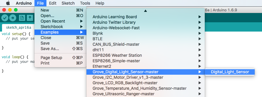
- Step 3. Open the code directly by the path: File -> Example ->Digital_Light_Sensor->Digital_Light_Sensor.
- Or copy below code to IDE and upload to Arduino.
/*
    Digital_Light_Sensor.ino
    A library for TSL2561

    Copyright (c) 2012 seeed technology inc.
    Author     : zhangkun
    Create Time:
    Change Log :

    The MIT License (MIT)

    Permission is hereby granted, free of charge, to any person obtaining a copy
    of this software and associated documentation files (the "Software"), to deal
    in the Software without restriction, including without limitation the rights
    to use, copy, modify, merge, publish, distribute, sublicense, and/or sell
    copies of the Software, and to permit persons to whom the Software is
    furnished to do so, subject to the following conditions:

    The above copyright notice and this permission notice shall be included in
    all copies or substantial portions of the Software.

    THE SOFTWARE IS PROVIDED "AS IS", WITHOUT WARRANTY OF ANY KIND, EXPRESS OR
    IMPLIED, INCLUDING BUT NOT LIMITED TO THE WARRANTIES OF MERCHANTABILITY,
    FITNESS FOR A PARTICULAR PURPOSE AND NONINFRINGEMENT. IN NO EVENT SHALL THE
    AUTHORS OR COPYRIGHT HOLDERS BE LIABLE FOR ANY CLAIM, DAMAGES OR OTHER
    LIABILITY, WHETHER IN AN ACTION OF CONTRACT, TORT OR OTHERWISE, ARISING FROM,
    OUT OF OR IN CONNECTION WITH THE SOFTWARE OR THE USE OR OTHER DEALINGS IN
    THE SOFTWARE.
*/

#include <Wire.h>
#include <Digital_Light_TSL2561.h>
void setup()
{
  Wire.begin();
  Serial.begin(9600);
  TSL2561.init();
}

void loop()
{
  Serial.print("The Light value is: ");
  Serial.println(TSL2561.readVisibleLux());
  delay(1000);
}
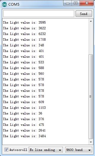
- Step 4. Open the serial monitor to monitor the result.
Play With Raspberry Pi
Hardware
- Step 1. Prepare the below stuffs:
| Raspberry pi | GrovePi_Plus | Grove - Digital light sensor |
|---|---|---|
 | 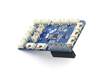 | |
| Get ONE Now | Get ONE Now | Get ONE Now |
- Follow instruction to configure the development environment.
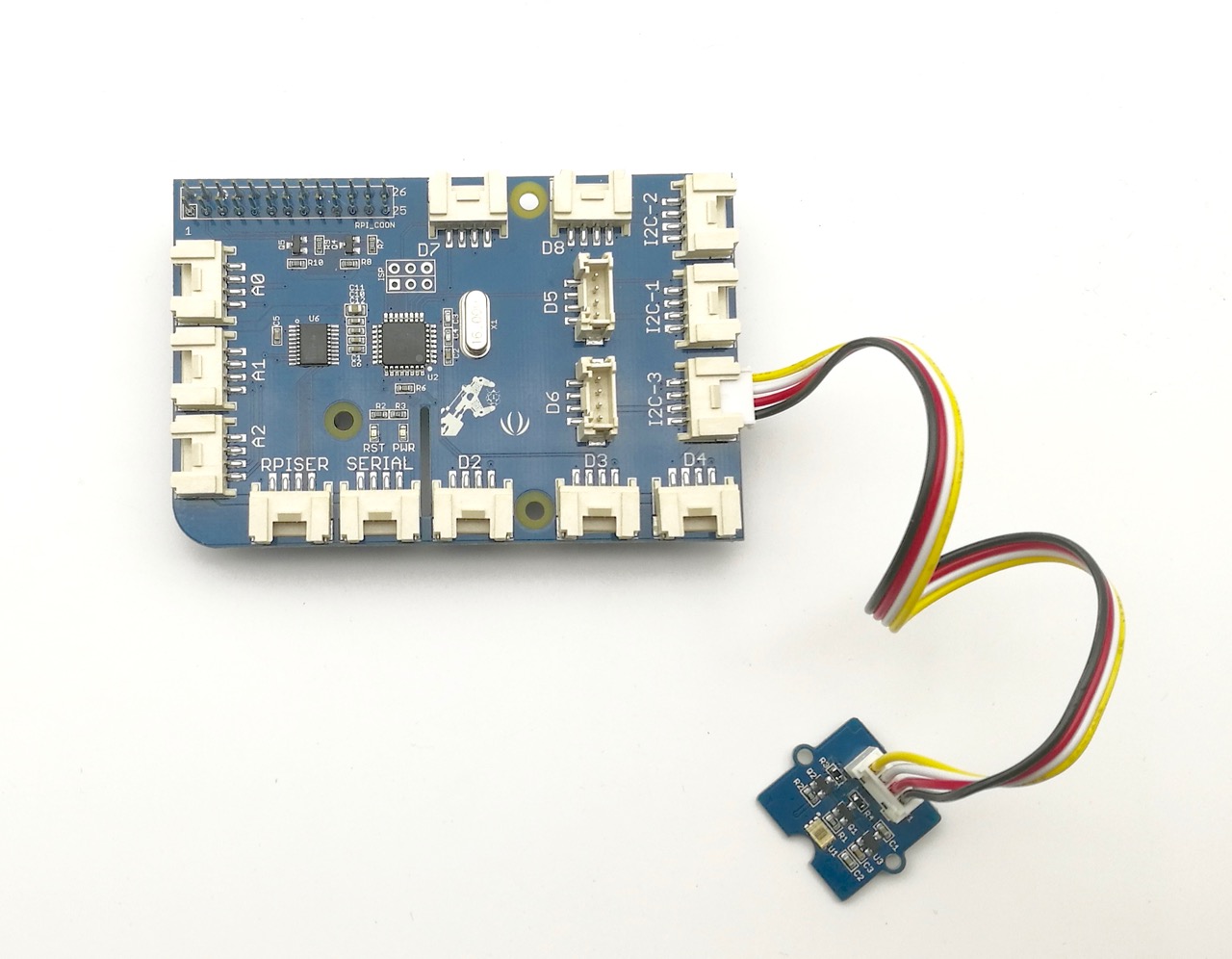
- Plug the sensor to grovepi+ socket I2C by using a grove cable.
Software
If you are using Raspberry Pi with Raspberrypi OS >= Bullseye, you have to use this command line only with Python3.
-
Step 1. Follow Setting Software to configure the development environment.
-
Step 1. Navigate to the demos' directory:
cd yourpath/GrovePi/Software/Python/grove_i2c_digital_light_sensor/
- Step 2. To see the code
nano grove_i2c_digital_light_sensor.py # "Ctrl+x" to exit #
#!/usr/bin/python
# TSL2561 I2C Light-To-Digital converter library for the Raspberry Pi.
# Datasheet: https://www.adafruit.com/datasheets/TSL2561.pdf
#
# This library is based on the work by Cedric Maion https://github.com/cmaion/TSL2561
#
# Read http://www.dexterindustries.com/topic/greehouse-project/ for the forum discussion about the sensor

from time import sleep
import smbus
from Adafruit_I2C import Adafruit_I2C
import RPi.GPIO as GPIO
from smbus import SMBus

TSL2561_Control = 0x80
TSL2561_Timing = 0x81
TSL2561_Interrupt = 0x86
TSL2561_Channel0L = 0x8C
TSL2561_Channel0H = 0x8D
TSL2561_Channel1L = 0x8E
TSL2561_Channel1H = 0x8F

TSL2561_Address = 0x29 #device address

LUX_SCALE = 14 # scale by 2^14
RATIO_SCALE = 9 # scale ratio by 2^9
CH_SCALE = 10 # scale channel values by 2^10
CHSCALE_TINT0 = 0x7517 # 322/11 * 2^CH_SCALE
CHSCALE_TINT1 = 0x0fe7 # 322/81 * 2^CH_SCALE

K1T = 0x0040 # 0.125 * 2^RATIO_SCALE
B1T = 0x01f2 # 0.0304 * 2^LUX_SCALE
M1T = 0x01be # 0.0272 * 2^LUX_SCALE
K2T = 0x0080 # 0.250 * 2^RATIO_SCA
B2T = 0x0214 # 0.0325 * 2^LUX_SCALE
M2T = 0x02d1 # 0.0440 * 2^LUX_SCALE
K3T = 0x00c0 # 0.375 * 2^RATIO_SCALE
B3T = 0x023f # 0.0351 * 2^LUX_SCALE
M3T = 0x037b # 0.0544 * 2^LUX_SCALE
K4T = 0x0100 # 0.50 * 2^RATIO_SCALE
B4T = 0x0270 # 0.0381 * 2^LUX_SCALE
M4T = 0x03fe # 0.0624 * 2^LUX_SCALE
K5T = 0x0138 # 0.61 * 2^RATIO_SCALE
B5T = 0x016f # 0.0224 * 2^LUX_SCALE
M5T = 0x01fc # 0.0310 * 2^LUX_SCALE
K6T = 0x019a # 0.80 * 2^RATIO_SCALE
B6T = 0x00d2 # 0.0128 * 2^LUX_SCALE
M6T = 0x00fb # 0.0153 * 2^LUX_SCALE
K7T = 0x029a # 1.3 * 2^RATIO_SCALE
B7T = 0x0018 # 0.00146 * 2^LUX_SCALE
M7T = 0x0012 # 0.00112 * 2^LUX_SCALE
K8T = 0x029a # 1.3 * 2^RATIO_SCALE
B8T = 0x0000 # 0.000 * 2^LUX_SCALE
M8T = 0x0000 # 0.000 * 2^LUX_SCALE


K1C = 0x0043 # 0.130 * 2^RATIO_SCALE
B1C = 0x0204 # 0.0315 * 2^LUX_SCALE
M1C = 0x01ad # 0.0262 * 2^LUX_SCALE
K2C = 0x0085 # 0.260 * 2^RATIO_SCALE
B2C = 0x0228 # 0.0337 * 2^LUX_SCALE
M2C = 0x02c1 # 0.0430 * 2^LUX_SCALE
K3C = 0x00c8 # 0.390 * 2^RATIO_SCALE
B3C = 0x0253 # 0.0363 * 2^LUX_SCALE
M3C = 0x0363 # 0.0529 * 2^LUX_SCALE
K4C = 0x010a # 0.520 * 2^RATIO_SCALE
B4C = 0x0282 # 0.0392 * 2^LUX_SCALE
M4C = 0x03df # 0.0605 * 2^LUX_SCALE
K5C = 0x014d # 0.65 * 2^RATIO_SCALE
B5C = 0x0177 # 0.0229 * 2^LUX_SCALE
M5C = 0x01dd # 0.0291 * 2^LUX_SCALE
K6C = 0x019a # 0.80 * 2^RATIO_SCALE
B6C = 0x0101 # 0.0157 * 2^LUX_SCALE
M6C = 0x0127 # 0.0180 * 2^LUX_SCALE
K7C = 0x029a # 1.3 * 2^RATIO_SCALE
B7C = 0x0037 # 0.00338 * 2^LUX_SCALE
M7C = 0x002b # 0.00260 * 2^LUX_SCALE
K8C = 0x029a # 1.3 * 2^RATIO_SCALE
B8C = 0x0000 # 0.000 * 2^LUX_SCALE
M8C = 0x0000 # 0.000 * 2^LUX_SCALE

# bus parameters
rev = GPIO.RPI_REVISION
if rev == 2 or rev == 3:
 bus = smbus.SMBus(1)
else:
 bus = smbus.SMBus(0)
i2c = Adafruit_I2C(TSL2561_Address)

debug = False
cooldown_time = 0.005 # measured in seconds
packageType = 0 # 0=T package, 1=CS package
gain = 0        # current gain: 0=1x, 1=16x [dynamically selected]
gain_m = 1      # current gain, as multiplier
timing = 2      # current integration time: 0=13.7ms, 1=101ms, 2=402ms [dynamically selected]
timing_ms = 0   # current integration time, in ms
channel0 = 0    # raw current value of visible+ir sensor
channel1 = 0    # raw current value of ir sensor
schannel0 = 0   # normalized current value of visible+ir sensor
schannel1 = 0   # normalized current value of ir sensor


def readRegister(address):
 try:
  byteval = i2c.readU8(address)

  sleep(cooldown_time)
  if (debug):
   print("TSL2561.readRegister: returned 0x%02X from reg 0x%02X" % (byteval, address))
  return byteval
 except IOError:
  print("TSL2561.readRegister: error reading byte from reg 0x%02X" % address)
  return -1


def writeRegister(address, val):
 try:
  i2c.write8(address, val)

  sleep(cooldown_time)
  if (debug):
   print("TSL2561.writeRegister: wrote 0x%02X to reg 0x%02X" % (val, address))
 except IOError:

  sleep(cooldown_time)
  print("TSL2561.writeRegister: error writing byte to reg 0x%02X" % address)
  return -1

def powerUp():
 writeRegister(TSL2561_Control, 0x03)

def powerDown():
 writeRegister(TSL2561_Control, 0x00)

def setTintAndGain():
 global gain_m, timing_ms

 if gain == 0:
  gain_m = 1
 else:
  gain_m = 16

 if timing == 0:
  timing_ms = 13.7
 elif timing == 1:
  timing_ms = 101
 else:
  timing_ms = 402
 writeRegister(TSL2561_Timing, timing | gain << 4)

def readLux():
 sleep(float(timing_ms + 1) / 1000)

 ch0_low  = readRegister(TSL2561_Channel0L)
 ch0_high = readRegister(TSL2561_Channel0H)
 ch1_low  = readRegister(TSL2561_Channel1L)
 ch1_high = readRegister(TSL2561_Channel1H)

 global channel0, channel1
 channel0 = (ch0_high<<8) | ch0_low
 channel1 = (ch1_high<<8) | ch1_low

 sleep(cooldown_time)
 if debug:
  print("TSL2561.readVisibleLux: channel 0 = %i, channel 1 = %i [gain=%ix, timing=%ims]" % (channel0, channel1, gain_m, timing_ms))

def readVisibleLux():
 global timing, gain

 powerUp()
 readLux()

 if channel0 < 500 and timing == 0:
  timing = 1
  sleep(cooldown_time)
  if debug:
   print("TSL2561.readVisibleLux: too dark. Increasing integration time from 13.7ms to 101ms")
  setTintAndGain()
  readLux()

 if channel0 < 500 and timing == 1:
  timing = 2
  sleep(cooldown_time)
  if debug:
   print("TSL2561.readVisibleLux: too dark. Increasing integration time from 101ms to 402ms")
  setTintAndGain()
  readLux()

 if channel0 < 500 and timing == 2 and gain == 0:
  gain = 1
  sleep(cooldown_time)
  if debug:
   print("TSL2561.readVisibleLux: too dark. Setting high gain")
  setTintAndGain()
  readLux()

 if (channel0 > 20000 or channel1 > 20000) and timing == 2 and gain == 1:
  gain = 0
  sleep(cooldown_time)
  if debug:
   print("TSL2561.readVisibleLux: enough light. Setting low gain")
  setTintAndGain()
  readLux()

 if (channel0 > 20000 or channel1 > 20000) and timing == 2:
  timing = 1
  sleep(cooldown_time)
  if debug:
   print("TSL2561.readVisibleLux: enough light. Reducing integration time from 402ms to 101ms")
  setTintAndGain()
  readLux()

 if (channel0 > 10000 or channel1 > 10000) and timing == 1:
  timing = 0
  sleep(cooldown_time)
  if debug:
   print("TSL2561.readVisibleLux: enough light. Reducing integration time from 101ms to 13.7ms")
  setTintAndGain()
  readLux()

 powerDown()

 if (timing == 0 and (channel0 > 5000 or channel1 > 5000)) or (timing == 1 and (channel0 > 37000 or channel1 > 37000)) or (timing == 2 and (channel0 > 65000 or channel1 > 65000)):
  # overflow
  return -1

 return calculateLux(channel0, channel1)

def calculateLux(ch0, ch1):
 chScale = 0
 if timing == 0:   # 13.7 msec
  chScale = CHSCALE_TINT0
 elif timing == 1: # 101 msec
  chScale = CHSCALE_TINT1;
 else:           # assume no scaling
  chScale = (1 << CH_SCALE)

 if gain == 0:
  chScale = chScale << 4 # scale 1X to 16X

 # scale the channel values
 global schannel0, schannel1
 schannel0 = (ch0 * chScale) >> CH_SCALE
 schannel1 = (ch1 * chScale) >> CH_SCALE

 ratio = 0
 if schannel0 != 0:
  ratio = (schannel1 << (RATIO_SCALE+1)) / schannel0
 ratio = (ratio + 1) >> 1

 if packageType == 0: # T package
  if ((ratio >= 0) and (ratio <= K1T)):
   b=B1T; m=M1T;
  elif (ratio <= K2T):
   b=B2T; m=M2T;
  elif (ratio <= K3T):
   b=B3T; m=M3T;
  elif (ratio <= K4T):
   b=B4T; m=M4T;
  elif (ratio <= K5T):
   b=B5T; m=M5T;
  elif (ratio <= K6T):
   b=B6T; m=M6T;
  elif (ratio <= K7T):
   b=B7T; m=M7T;
  elif (ratio > K8T):
   b=B8T; m=M8T;
 elif packageType == 1: # CS package
  if ((ratio >= 0) and (ratio <= K1C)):
   b=B1C; m=M1C;
  elif (ratio <= K2C):
   b=B2C; m=M2C;
  elif (ratio <= K3C):
   b=B3C; m=M3C;
  elif (ratio <= K4C):
   b=B4C; m=M4C;
  elif (ratio <= K5C):
   b=B5C; m=M5C;
  elif (ratio <= K6C):
   b=B6C; m=M6C;
  elif (ratio <= K7C):
   b=B7C; m=M7C;

 temp = ((schannel0*b)-(schannel1*m))
 if temp < 0:
  temp = 0;
 temp += (1<<(LUX_SCALE-1))
 # strip off fractional portion
 lux = temp>>LUX_SCALE
 sleep(cooldown_time)
 if debug:
  print("TSL2561.calculateLux: %i" % lux)

 return lux

def init():
 powerUp()
 setTintAndGain()
 writeRegister(TSL2561_Interrupt, 0x00)
 powerDown()

def main():
 init()
 while (True):
  print("Lux: %i [Vis+IR=%i, IR=%i @ Gain=%ix, Timing=%.1fms]" % (readVisibleLux(), channel0, channel1, gain_m, timing_ms))
  sleep(1)

if __name__ == "__main__":
        main()
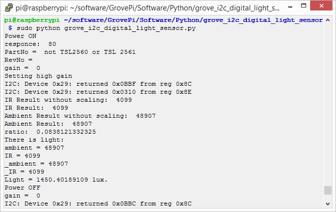
- Step 3. Run the demo.
sudo python3 grove_i2c_digital_light_sensor.py
- Step 4. Here is the Result.
Schematic Online Viewer
Resources
- [Eagle] Grove - Digital Light Sensor Schematic
- [PDF] Grove - Digital Light Sensor Sch PDF File
- [PDF] Grove - Digital Light Sensor PCB PDF File
- [Library] Library Github Grove-Digital Light
- [Datasheet] TSL2561 Datasheet
Projects
Seeed LoRa IoTea Solution: An automatic information collection system applied to tea plantation. It is part of intelligent agricultural information collection.
Intel Edison IoT Hydroponic Controller: An IoT enabled Hydroponics Controller using the Intel Edison during the Boston IoT Hackathon.
COI - Light Transmission Meter: The finished product uses the light sensor provided in the Grove Starter Kit Plus to measure change in light intensity.
Tech Support & Product Discussion
Thank you for choosing our products! We are here to provide you with different support to ensure that your experience with our products is as smooth as possible. We offer several communication channels to cater to different preferences and needs.