Grove - Light Sensor
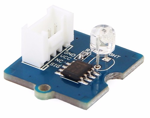
The Grove - Light sensor integrates a photo-resistor(light dependent resistor) to detect the intensity of light. The resistance of photo-resistor decreases when the intensity of light increases. A dual OpAmp chip LM358 on board produces voltage corresponding to intensity of light(i.e. based on resistance value). The output signal is analog value, the brighter the light is, the larger the value.
This module can be used to build a light controlled switch i.e. switch off lights during day time and switch on lights during night time.
The light sensor value only reflects the approximated trend of the intensity of light, it DOES NOT represent the exact Lumen.
![]()
Upgradable to Industrial Sensors
With the SenseCAP S2110 controller and S2100 data logger, you can easily turn the Grove into a LoRaWAN® sensor. Seeed not only helps you with prototyping but also offers you the possibility to expand your project with the SenseCAP series of robust industrial sensors.
SenseCAP S210x series industrial sensors provide an out-of-box experience for environmental sensing. Please refer to the S2102 Wireless Light Intensity Sensor with higher performance and robustness for light intensity detection. The series includes sensors for soil moisture, air temperature and humidity, light intensity, CO2, EC, and an 8-in-1 weather station. Try the latest SenseCAP S210x for your next successful industrial project.
| SenseCAP Industrial Sensor |
 |
| S2102 Light |
Version
| Product Version | Changes | Released Date |
|---|---|---|
| Grove - Light Sensor 1.0 | Initial | Apr 28 2013 |
| Grove - Light Sensor(P) | Move Grove connector to back side | May 15 2014 |
| Grove - Light Sensor(P) V1.1 | Replace photoresistor-5528 with LS06-S Vs.Grove - Light Sensor(P) | Dec 31 2015 |
| Grove - Light Sensor 1.2 | Replace photoresistor-5528 with LS06-S Vs.Grove - Light Sensor 1.0 | Jan 20 2016 |
Features
-
Analog value output
-
High reliability and sensibility
-
Small footprint
-
Recognize wider spectrum
More details about Grove modules please refer to Grove System
Platform Support
| Arduino | Raspberry Pi | |||
|---|---|---|---|---|
The platforms mentioned above as supported is/are an indication of the module's software or theoritical compatibility. We only provide software library or code examples for Arduino platform in most cases. It is not possible to provide software library / demo code for all possible MCU platforms. Hence, users have to write their own software library.
Specification
| Item | Value |
|---|---|
| Operating voltage | 3~5V |
| Operating current | 0.5~3 mA |
| Response time | 20-30 milliseconds |
| Peak Wavelength | 540 nm |
| Weight | 4 g |
Getting Started
Play With Arduino
Hardware
- Step 1. Prepare the below stuffs:
| Seeeduino V4 | Base Shield | Grove - Light Sensor | Grove - LED Bar |
|---|---|---|---|
 |  |  |  |
| Get One Now | Get One Now | Get One Now | Get One Now |
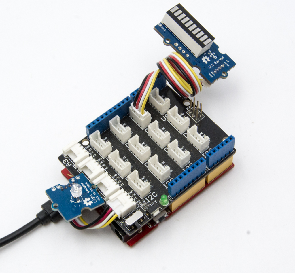
- Step 2. Connect Grove-Light Sensor to port A0 of Grove-Base Shield.
- Step 3. Connect Grove-Led Bar to port D2 of Grove-Base Shield.
- Step 4. Plug Grove - Base Shield into Seeeduino.
- Step 5. Connect Seeeduino to PC through a USB cable.
If we don't have Grove Base Shield, We also can directly connect Grove-Light Sensor to Seeeduino as below.
| Seeeduino | Grove-Light Sensor |
|---|---|
| 5V | Red |
| GND | Black |
| Not Conencted | White |
| A0 | Yellow |
| Seeeduino | Grove-Led Bar |
|---|---|
| 5V | Red |
| GND | Black |
| D3 | White |
| D2 | Yellow |
Software
- Step 1. Download the Grove-LED Bar Library from Github.
- Step 2. Refer How to install library to install library for Seeeduino.
- Step 3. Copy the code into Seeeduino IDE and upload.
#include <Grove_LED_Bar.h>

Grove_LED_Bar bar(3, 2, 0);  // Clock pin, Data pin, Orientation

void setup()
{
  // nothing to initialize
  bar.begin();
  bar.setGreenToRed(true);
}

void loop()
{

  int value = analogRead(A0);
  value = map(value, 0, 800, 0, 10);

  bar.setLevel(value);
  delay(100);
}
- Step 2. The Led bar will change base on light.
Play with Codecraft
Hardware
Step 1. Connect a Grove - Light Sensor to port A0 of a Base Shield.
Step 2. Plug the Base Shield to your Seeeduino/Arduino.
Step 3. Link Seeeduino/Arduino to your PC via an USB cable.
Software
Step 1. Open Codecraft, add Arduino support, and drag a main procedure to working area.
If this is your first time using Codecraft, see also Guide for Codecraft using Arduino.
Step 2. Drag blocks as picture below or open the cdc file which can be downloaded at the end of this page.
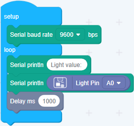
Upload the program to your Arduino/Seeeduino.
When the code finishes uploaded, you will see the brightnedd value displayed in the Serial Monitor.
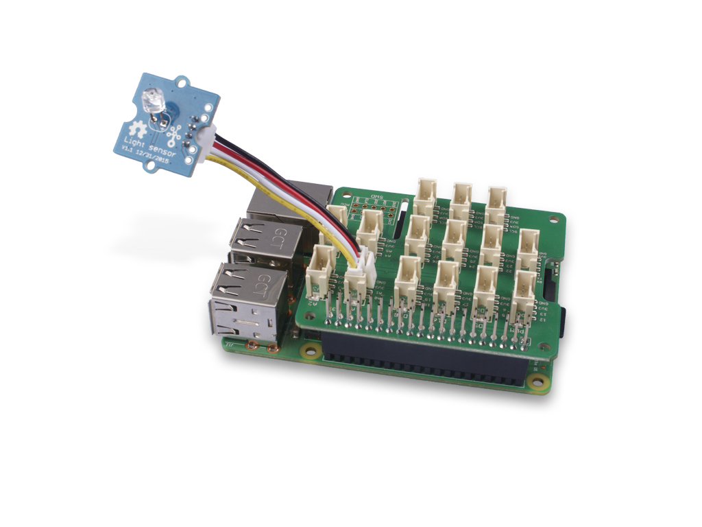
Play With Raspberry Pi (With Grove Base Hat for Raspberry Pi)
Hardware
- Step 1. Things used in this project:
| Raspberry pi | Grove Base Hat for RasPi | Grove - Light Sensor |
|---|---|---|
 | 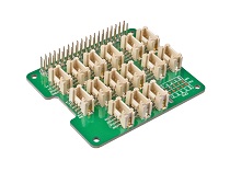 | |
| Get ONE Now | Get ONE Now | Get ONE Now |
- Step 2. Plug the Grove Base Hat into Raspberry.
- Step 3. Connect the light sensor to port A0 of the Base Hat.
- Step 4. Connect the Raspberry Pi to PC through USB cable.
For step 3 you are able to connect the light sensor to any Analog Port but make sure you change the command with the corresponding port number.
Software
If you are using Raspberry Pi with Raspberrypi OS >= Bullseye, you have to use this command line only with Python3.
- Step 1. Follow Setting Software to configure the development environment.
- Step 2. Download the source file by cloning the grove.py library.
cd ~
git clone https://github.com/Seeed-Studio/grove.py
- Step 3. Excute below commands to run the code.
cd grove.py/grove
python3 grove_light_sensor_v1_2.py 0
Following is the grove_light_sensor_v1_2.py code.
import math
import sys
import time
from grove.adc import ADC


class GroveLightSensor:

    def __init__(self, channel):
        self.channel = channel
        self.adc = ADC()

    @property
    def light(self):
        value = self.adc.read(self.channel)
        return value

Grove = GroveLightSensor


def main():
    if len(sys.argv) < 2:
        print('Usage: {} adc_channel'.format(sys.argv[0]))
        sys.exit(1)

    sensor = GroveLightSensor(int(sys.argv[1]))

    print('Detecting light...')
    while True:
        print('Light value: {0}'.format(sensor.light))
        time.sleep(1)

if __name__ == '__main__':
    main()
If everything goes well, you will be able to see the following result corresponding to the surrounding light
pi@raspberrypi:~/grove.py/grove $ python3 grove_light_sensor_v1_2.py 0
Detecting light...
Light value: 600
Light value: 448
Light value: 267
Light value: 311
Light value: 102
Light value: 82
Light value: 63
Light value: 54
Light value: 49
Light value: 45
Light value: 545
^CTraceback (most recent call last):
  File "grove_light_sensor_v1_2.py", line 67, in <module>
    main()
  File "grove_light_sensor_v1_2.py", line 64, in main
    time.sleep(1)
KeyboardInterrupt
You can quit this program by simply press ++ctrl+c++.
You may have noticed that for the analog port, the silkscreen pin number is something like A1, A0, however in the command we use parameter 0 and 1, just the same as digital port. So please make sure you plug the module into the correct port, otherwise there may be pin conflicts.
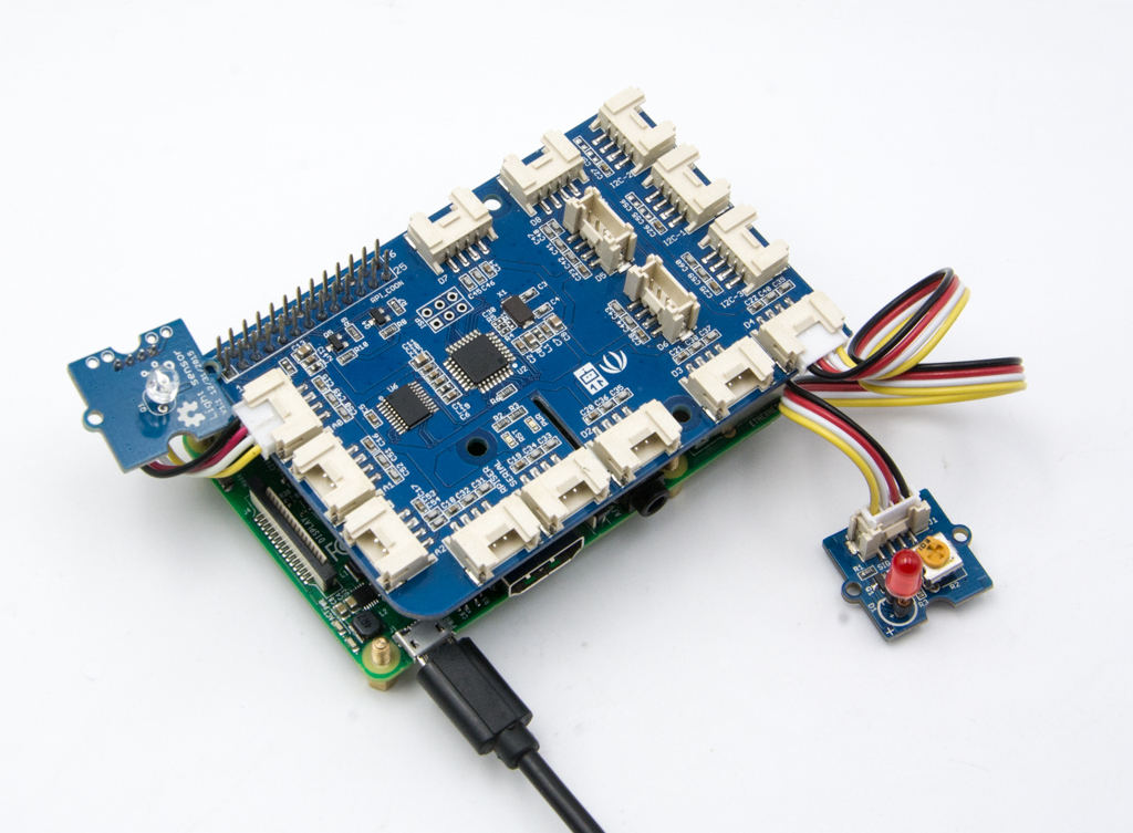
Play With Raspberry Pi (with GrovePi_Plus)
Hardware
- Step 1. Prepare the below stuffs:
| Raspberry pi | GrovePi_Plus | Grove - Light Sensor | Grove - Red LED |
|---|---|---|---|
| 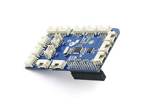 | |  |
| Get One Now | Get One Now | Get One Now | Get One Now |
- Step 2. Plug the GrovePi_Plus into Raspberry.
- Step 3. Connect Grove-light sensor to A0 port of GrovePi_Plus.
- Step 4. Connect Grove-Red Led to D4 port of GrovePi_Plus.
- Step 5. Connect the Raspberry to PC through USB cable.
Software
If you are using Raspberry Pi with Raspberrypi OS >= Bullseye, you have to use this command line only with Python3.
- Step 1. Follow Setting Software to configure the development environment.
- Step 2. Git clone the Github repository.
cd ~
git clone https://github.com/DexterInd/GrovePi.git
- Step 3. Excute below commands.
cd ~/GrovePi/Software/Python
python3 grove_light_sensor.py
Here is the grove_light_sensor.py code.
import time
import grovepi

# Connect the Grove Light Sensor to analog port A0
# SIG,NC,VCC,GND
light_sensor = 0

# Connect the LED to digital port D4
# SIG,NC,VCC,GND
led = 4

# Turn on LED once sensor exceeds threshold resistance
threshold = 10

grovepi.pinMode(light_sensor,"INPUT")
grovepi.pinMode(led,"OUTPUT")

while True:
    try:
        # Get sensor value
        sensor_value = grovepi.analogRead(light_sensor)

        # Calculate resistance of sensor in K
        resistance = (float)(1023 - sensor_value) * 10 / sensor_value

        if resistance > threshold:
            # Send HIGH to switch on LED
            grovepi.digitalWrite(led,1)
        else:
            # Send LOW to switch off LED
            grovepi.digitalWrite(led,0)

        print("sensor_value = %d resistance = %.2f" %(sensor_value,  resistance))
        time.sleep(.5)

    except IOError:
        print ("Error")
- Step 4. The led will turn on when the light sensor gets covered.
pi@raspberrypi:~/GrovePi/Software/Python $ python3 grove_light_sensor.py
sensor_value = 754 resistance = 3.57
sensor_value = 754 resistance = 3.57
sensor_value = 752 resistance = 3.60
sensor_value = 752 resistance = 3.60
sensor_value = 752 resistance = 3.60
sensor_value = 313 resistance = 22.68
sensor_value = 155 resistance = 56.00
sensor_value = 753 resistance = 3.59
Eagle File for Grove - Light Sensor V1.0
Eagle File for Grove - Light Sensor(P) V1.0
Eagle File for Grove - Light Sensor(P) V1.1
Resources
- [Codecraft] CDC File
- [Eagle&PDF] Eagle File for Grove - Light Sensor V1.0
- [Eagle&PDF] Eagle File for Grove - Light Sensor(P) V1.0
- [Eagle&PDF] Eagle File for Grove - Light Sensor(P) V1.1
- [Datasheet] LS06-MΦ5 Reference Information
- [Datasheet] LM358.PDF
- [More Reading] Secret Box
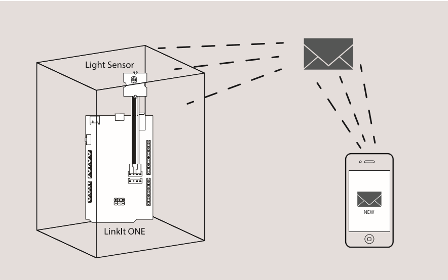
Here we will show you a project made with Grove - Light Sensor - Secret Box. First you need a box, a paper box, wooden box, any box is ok. Put something in the box, because we named it secret box, that means we don't want anybody to open it, otherwise there will be an alarm to inform you.
Here we use LinkIt ONE as the controller, which is an Arduino compatible board and consist of rich function. And you need things below:
- LinkIt ONE
- Grove - Light Sensor
- Grove - Base Shield
- A Sim Card
Let's connect Grove - Light Sensor to A0 or Base Shield, and open Arduino IDE, copy below code and upload the example to LinkIt ONE. Then someone open the box, the light will detect it, and send you a SMS.
// demo of Grove Starter kit for LinkIt ONE
// Secret box

#include <LGSM.h>

char num[20] = "13425171053";           // your number write here
char text[100] = "Warning: Your box had been opened!!";    // what do you want to send


const int pinLight = A0;                // light sensor connect to A0

bool isLightInBox()
{
    return (analogRead(pinLight)<50);   // when get data less than 50, means light sensor was in box
}

void setup()
{
    Serial.begin(115200);

    while(!isLightInBox());             // until put in box
    delay(2000);
}


void loop()
{
    if(!isLightInBox())                 // box is open
    {
        Serial.println("box had been opened");

        while(!LSMS.ready())
        {
            delay(1000);
        }

        Serial.println("SIM ready for work!");
        LSMS.beginSMS(num);
        LSMS.print(text);

        if(LSMS.endSMS())
        {
            Serial.println("SMS is sent");
        }
        else
        {
            Serial.println("SMS send fail");
        }

        while(!isLightInBox());             // until put in box
        delay(2000);
    }

    delay(10);
}
Have fun.
Projects
Grove - Introduction in a Light Sensor:
The Environment Cube! Know the Land Beneath You using Sigfox: A cube with all the necessary sensors, suitable for a wide range of applications like agriculture, monitoring, ,etc.
Light sensor Grove module:
Tech Support & Product Discussion
Thank you for choosing our products! We are here to provide you with different support to ensure that your experience with our products is as smooth as possible. We offer several communication channels to cater to different preferences and needs.