RS-485 Shield for Raspberry Pi

RS-485 is a cost-effective solution in serial communication networks. It can be used up to data rates at 10 Mbit/s or distances up to 1200m at lower speeds. This RS-485 Shield is a standard add-on board for Raspberry Pi. It is integrated with simple screw terminal as well as DB9 interface.

Version
| Product Version | Changes | Released Date |
|---|---|---|
| RS-485 Shield for Raspberry Pi | Initial | Sep 2018 |
Feature
- One driver and one receiver per part
- EMI noise minimization
- Transmission rate up to 2.5Mbps
- No driver slew rate limitation
- Short-circuit current limited
- Fail-Safe Applications
- Support Raspberry Pi 3B/3B+/4
Specification
| Item | Value |
|---|---|
| Operating Supply Voltage | 3.3V |
| Interface | RS-485 DB9 Interface X1 RS-485 Screw Interface X1 2×13 Female Header To Raspberry X1 2×13 Expansion Female Header X1 Grove I2C Interface X1 |
| Data Rate | 2.5Mbps |
| Number of Receivers on | 32 |
| Storage Temperature Range | -65~160℃ |
| Channel Number | 8 |
| Resolution | 12-Bit |
| Power Consumption | Different power consumption depending on the transmission rate |
| size | L: 62mm W: 39.2mm H: 21.8mm |
| Weight | 23g |
| Package size | L: 140mm W: 75mm H: 25mm |
| Gross Weight | 42g |
Typical Applications
- Low-Power RS-485 Transceivers
- Level Translators
- Transceivers for EMI-Sensitive Applications Industrial-Control Local Area Networks
- Half-duplex applications
Hardware Overview
Pin Out
Overview

RS-485 DB9 Interface & RS-485 Screw Interface

The 485 interface uses differential signal transmission. Please make sure the port A connect to the port A of the 485 device, and port B connect to the port B of the 485 device.
485-A: The end A of RS485 data transmit wire, connect to the pin A of the MAX485 chip.
485-B: The end B of RS485 data transmit wire, connect to the pin B of the MAX485 chip.
GND: Connect to the Raspberry Pi GND.
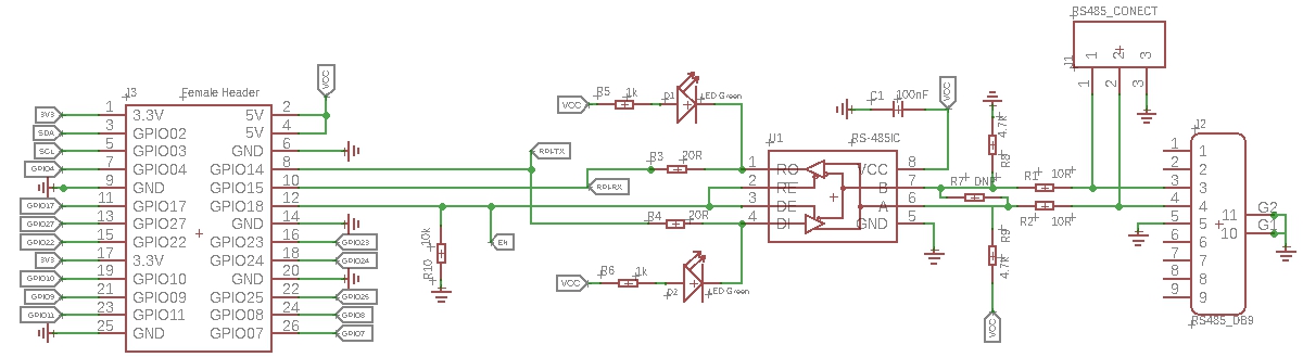
You can click the picture to view the original file
As you can see, GPIO14 and GPIO15 are applied for data transmission, and we use GPIO18 as the enable signal.
For the definition of logic signals, please refer to the table below.

Female Headers to Raspberry

We use a 2X13 Female Header to plug this module into the Raspberry Pi, please make sure the pins are aligned.

Extension Female Headers

This RS-485 Shield occupies 26 Raspberry Pi pins, and only 5 GPIO pins are actually used. We take these 26 pins out in case you need those pins for other purposes.
GPIO Occupied List
| GPIO Number | Function |
|---|---|
| GPIO02 | SDA for Grove I2C Port |
| GPIO03 | SCL for Grove I2C Port |
| GPIO14 | Connect to the pin DI of Max485 chip, for data transmission. |
| GPIO15 | Connect to the pin RO of Max485 chip, for data transmission. |
| GPIO18 | Connect to the pin RE & DE of Max485 chip, work as the enable signal. |
Grove I2C Port

We have reserved the I2C interface so that you can easily use it with I2C devices. It should be noted that the VCC of this port is 5V, you need to confirm that whether the module is compatible with 5V voltage.
SCL: I2C serial clock, connect to the GPIO03 of Raspberry Pi.
SDA: I2C serial data, connect to the GPIO02 of Raspberry Pi.
VCC: Connect to the Raspberry Pi 5V pin.
GND: Connect to the Raspberry Pi GND pin.
Max485 Chip

We use the MAX485ESA IC for this shield, for more detail about this IC, please check the MAX485 Datasheet
Platforms Supported
| Arduino | Raspberry Pi | |||
|---|---|---|---|---|
Getting Started
Hardware
Materials required
| Raspberry pi | RS-485 Shield for Raspberry Pi |
|---|---|
 |  |
| Get ONE Now | Get ONE Now |
Step 1. Plug the RS-485 Shield for Raspberry Pi into the Raspberry Pi.
Step 2. Connect the 485-A to 485 wire A, connect the 485-B to 485 wire B.
If the wire is reversed, communication will not be possible.
- Step 3. Power the Raspberry Pi with micro-usb cable.
Software
Communication test code
You can create a new python file and copy the following code into the new file, or you can download the source file in the resource download area. Then run it in your terminal.
Sending Code.
#!/usr/bin/env python

import time
import serial
import os
from gpiozero import LED

send_str = "*******rs485888888--\n"

ser = serial.Serial(port='/dev/ttyS0',baudrate =115200)

Tx_Enable = LED(18)
Tx_Enable.on()

while 1:
    ser.write(send_str)
    time.sleep(1)
Receive Code
#!/usr/bin/env python

import time
import serial
import os
from gpiozero import LED

ser = serial.Serial(port='/dev/ttyS0',baudrate =115200,timeout=1)
data = ''

Rx_Disable = LED(18)
Rx_Disable.off()

while True:
    str = ser.readall()
    if str:
        print str
You need two shield and two raspberry to test the code above, or you can use the serial tool in the PC to communicate with your raspberry pi.
Schematic Online Viewer
Resources
[Zip] Python Test Code
[PDF] MAX485 Datasheet
[PDF] PDF Format Wiki
Tech Support & Product Discussion
. Thank you for choosing our products! We are here to provide you with different support to ensure that your experience with our products is as smooth as possible. We offer several communication channels to cater to different preferences and needs.