8-Channel 12-Bit ADC for Raspberry Pi (STM32F030)

ADC is a common accessory for Raspberry Pi. Nowadays many cheap MCUs has built-in ADC, so we make this 8-channel ADC based on STM32F030, which is a cost-effective, low-power ARM Cortex M0 MCU. We breakout 8 channels ADC from the MCU, and integrated 4 analog Grove connector so that you can also use analog Grove modules with it.

Feature
- CRC calculation unit
- 5-channel Direct memory access(DMA) controller
- Calendar RTC with alarm and periodic wakeup from Stop/Standby
- Timers
- Advanced-control timer
- General-purpose timers & Basic timers
- Independent and system watchdog timers
- SysTick timer
- Real-time clock (RTC)
- Serial wire debug (SWD)
- Support Raspberry Pi 3B/3B+/4
Specification
| Item | Value |
|---|---|
| Operating Supply Voltage | 3.3V |
| ADC Resolution | 12 bit |
| Maximum Clock Frequency | 48 MHz |
| Program Memory Size | 16kB |
| Data RAM Size | 4 kB |
| Data Bus Width | 32 bit |
| Operating Temperature | -40~85℃ |
| Communication Interfaces | I2C |
| I2C address | 0x04(default) |
| Size | L: 65mm W: 55mm H: 18mm |
| Weight | 25.9g |
| Package size | L: 140mm W: 75mm H: 25mm |
| Gross Weight | 45g |
Typical applications
- Temperature measurement
- Consumer goods
Hardware Overview
Pin Out
Overview

GPIO
The same pin out as the Raspberry Pi.

SWD
We use SWD port to burn the firmware to this board. In addition, you can see pin 9/pin 10/pin 11 in this section. Those three pins do not used by any Grove port, you are free to use them without worrying about pin conflicts.

Grove Analog Port
As there is no build-in ADC in the Raspberry Pi, so the STM32-based ADC board allows the analog sensor to work with your Raspberry Pi.
There are 4 grove analog sockets on this board such this ADC board can directly work with grove modules by using Grove - Universal 4 Pin Buckled 5cm Cable.
The analog sensor inputs the analog voltage into the 12-bit ADC. After the ADC converts the analog data to digital data, it inputs the digital data to the Raspberry Pi through the I2C interface.

Female pin header ports
Same as Grove analog port but this part instead of using Grove - Universal 4 Pin Buckled 5cm Cable you need to use Breadboard Jumper Wire Pack.
8 analog junction ports, A0 ~ A7.
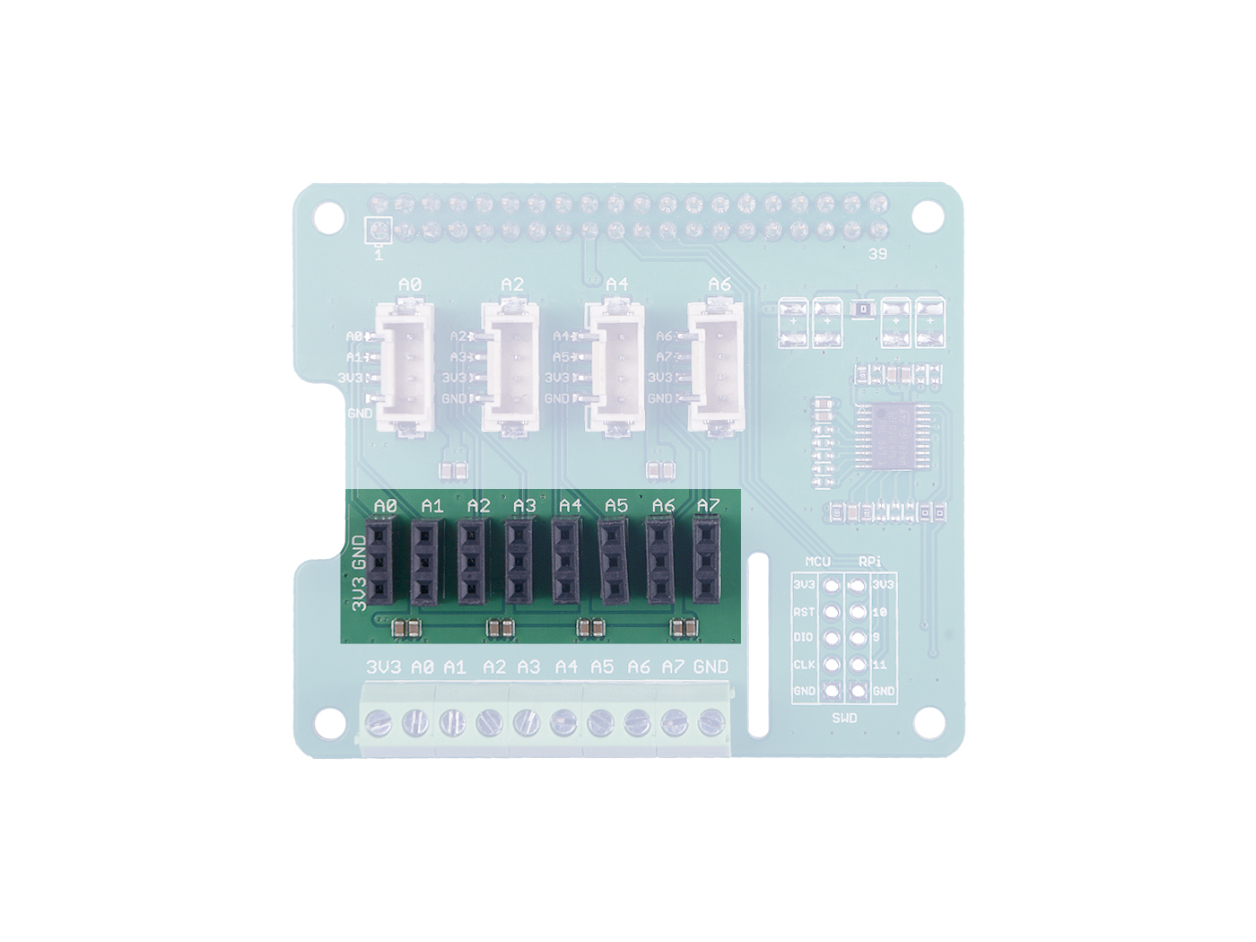
Screw terminal
Same as above but with different connection method. This group of pin connectors include analog pin A0 ~ A7, Vcc and GND.

Platforms Supported
| Arduino | Raspberry Pi | |||
|---|---|---|---|---|
Getting Started
Hardware
Materials required
| Raspberry pi | 8-Channel 12-Bit ADC for Raspberry Pi (STM32F030)(STM32F030) |
|---|---|
 |  |
| Get ONE Now | Get ONE Now |
- Step 1. Insert the 8-Channel 12-Bit ADC for Raspberry Pi (STM32F030) into Raspberry Pi.
- Step 2. Connect the Raspberry Pi to PC through USB cable.

Software
If you are using Raspberry Pi with Raspberrypi OS >= Bullseye, you have to use this command line only with Python3.
- Step 1. Download the source file by cloning the grove.py library.
cd ~
git clone https://github.com/Seeed-Studio/grove.py
- Step 2. Install the grove.py library
cd grove.py
# Python2
sudo pip install .
# Python3
sudo pip3 install .
- Step 3. Excute below commands to run the code.
cd grove.py/grove
python3 adc_8chan_12bit.py
Following is the adc_8chan_12bit.py code.
import time
from grove.i2c import Bus

ADC_DEFAULT_IIC_ADDR = 0X04

ADC_CHAN_NUM = 8

REG_RAW_DATA_START = 0X10
REG_VOL_START = 0X20
REG_RTO_START = 0X30

REG_SET_ADDR = 0XC0


class Pi_hat_adc():
    def __init__(self,bus_num=1,addr=ADC_DEFAULT_IIC_ADDR):
        self.bus=Bus(bus_num)
        self.addr=addr


    #get all raw adc data,THe max value is 4095,cause it is 12 Bit ADC
    def get_all_adc_raw_data(self):
        array = []
        for i in range(ADC_CHAN_NUM):
            data=self.bus.read_i2c_block_data(self.addr,REG_RAW_DATA_START+i,2)
            val=data[1]<<8|data[0]
            array.append(val)
        return array

    def get_nchan_adc_raw_data(self,n):
        data=self.bus.read_i2c_block_data(self.addr,REG_RAW_DATA_START+n,2)
        val =data[1]<<8|data[0]
        return val
    #get all data with unit mv.
    def get_all_vol_milli_data(self):
        array = []
        for i in range(ADC_CHAN_NUM):
            data=self.bus.read_i2c_block_data(self.addr,REG_VOL_START+i,2)
            val=data[1]<<8|data[0]
            array.append(val)
        return array

    def get_nchan_vol_milli_data(self,n):
        data=self.bus.read_i2c_block_data(self.addr,REG_VOL_START+n,2)
        val =data[1]<<8|data[0]
        return val

    #get all data ratio,unit is 0.1%
    def get_all_ratio_0_1_data(self):
        array = []
        for i in range(ADC_CHAN_NUM):
            data=self.bus.read_i2c_block_data(self.addr,REG_RTO_START+i,2)
            val=data[1]<<8|data[0]
            array.append(val)
        return array

    def get_nchan_ratio_0_1_data(self,n):
        data=self.bus.read_i2c_block_data(self.addr,REG_RTO_START+n,2)
        val =data[1]<<8|data[0]
        return val


ADC = Pi_hat_adc()
def main():
    raw_data=ADC.get_all_adc_raw_data()
    vol_data=ADC.get_all_vol_milli_data()
    ratio_data=ADC.get_all_ratio_0_1_data()
    print("raw data for each channel:(1-8chan)(12 bit-max=4096):")
    print(raw_data)
    print("voltage for each channel:(unit:mv,max=3300mv):")
    print(vol_data)
    print ("ratio for each channel(unit 0.1%,max=100.0%):")
    print(ratio_data)

    print(" ")
    print("NOTICE!!!:")
    print("The default setting of ADC PIN is floating_input.")
    print(" ")

if __name__ == '__main__':
    main()
If everything goes well, you will be able to see the following result
pi@raspberrypi:~/grove.py/grove $ python3 adc_8chan_12bit.py
raw data for each channel:(1-8chan)(12 bit-max=4096):
[2177, 2098, 2064, 2038, 2127, 2066, 2172, 2145]
voltage for each channel:(unit:mv,max=3300mv):
[1599, 1741, 1668, 1658, 1644, 1787, 1694, 1677]
ratio for each channel(unit 0.1%,max=100.0%):
[521, 544, 514, 504, 500, 559, 524, 505]

NOTICE!!!:
The default setting of ADC PIN is floating_input.
Example
If you are using Raspberry Pi with Raspberrypi OS >= Bullseye, you have to use this command line only with Python3.
We will take the Grove - Sound Sensor as an example to introduce you how to use this board.
Hardware connection
- Step 1. Plug the 8-Channel 12-Bit ADC for Raspberry Pi (STM32F030) into Raspberry Pi.
- Step 2. Connect the Grove - Sound Sensor to A0 port of the ADC module.
- Step 3. Connect the Raspberry Pi to PC through USB cable.
Hardware connection diagram

Tap the following command ++python grove_sound_sensor.py 0++ in the command line interface.
pi@raspberrypi:~/grove.py/grove $ python3 grove_sound_sensor.py 0
Detecting sound...
Sound value: 433
Sound value: 342
Sound value: 443
Sound value: 300
Sound value: 632
Sound value: 258
Sound value: 591
Sound value: 267
Sound value: 871
^CTraceback (most recent call last):
  File "grove_sound_sensor.py", line 67, in <module>
    main()
  File "grove_sound_sensor.py", line 64, in main
    time.sleep(.3)
KeyboardInterrupt
You can quit this program by simply press ctrl+c.
Schematic Online Viewer
Because ST32 series chips are out of stock globally, prices have increased several times and there is no clear delivery date. We have no choice but to switch to the MM32 chip. The specific replacement models are as follows: STM32F030F4P6TR is replaced by MM32F031F6P6. After the chip is replaced, the product functions, features, usage methods and codes remain unchanged. It should be noted that the firmware version has changed, and the factory firmware has been adjusted according to different chips. If you need to re-burn the firmware, please download the firmware corresponding to the chip.
Resources
[Zip] 8-Channel 12-Bit ADC for Raspberry Pi (STM32F030) (STM32F030) Eagle Files
[Zip] MM32F031F6P6-Firmware
[Zip] 8-Channel 12-Bit ADC for Raspberry Pi (STM32F030) (STM32F030) Software Library
[PDF] Datasheet STM32F030
Tech Support & Product Discussion
Thank you for choosing our products! We are here to provide you with different support to ensure that your experience with our products is as smooth as possible. We offer several communication channels to cater to different preferences and needs.