2 Channel CAN BUS FD Shield for Raspberry Pi

This is a CAN BUS shield for Raspberry Pi(hereinafter referred to as 2 channel pi hat), 2 channel CAN BUS I/O, support CAN FD. CAN FD support much faster transmission speed(up to 8Mbps)
Also it have two On-board 120Ω terminating resistors which are controlled by the switches.

Versions Declare
There are 3 versions of the CAN BUS shield for Raspberry Pi. All 3 versions work perfectly on Raspberry Pi platform, and may skip this section if you're using RPi platform.
The CAN BUS shield now only supports the Jetson Nano Developer Kit (SD card) and does not support Jetson Nano with eMMC (reComputer J1010/J1020v2). Different versions of the CAN BUS Shield do affect the functionality, please check the table below carefully if you're using with Jetson Nano Platform.
| Product Name | Chip | RPi State | Jetson Nano State |
|---|---|---|---|
| 2-Channel CAN-BUS(FD) Shield for RPi (MCP2517FD) | MCP2517FD | Two Channels | Single Channel(can0) |
| 2-Channel CAN-BUS(FD) Shield for Raspberry Pi (MCP2518FD) | MCP2518FD | Two Channels | Two Channels |
As you can see, there are two versions of chips used in the 2-Channel CAN-BUS(FD) Shield for RPi (MCP2517FD) and both channels work on RPi but only single channel (CAN0) works on the Jetson Nano Platform!
Features
- High-speed transfer rate: 8Mbps@10m 20AWG shielded cable / 1Mbps@40m 20AWG shielded cable
- Stable power supply, selectable Raspberry Pi power supply or DC power supply
- Compatible with Raspberry Pi 2, Raspberry Pi 3, Raspberry Pi 3, Raspberry Pi 4 and Raspberry Pi Zero
- One-button configuration of 120Ω terminating resistor
- Support CAN FD
Hardware Overview


Mounting Guide

You can see that we used nylon columns during assembly to avoid short-circuiting between the metal terminals under the CAN BUS port and the HDMI interface on the Raspberry Pi. So please be sure to assemble the nylon column as shown.
Specification
| Parameter | Value |
|---|---|
| Power Input | 12V~24V DC Raspberry Pi GPIO 5V |
| CAN FD Controller | MCP2517FD |
| CAN FD Transceiver | MCP2557FD |
| CAN FD Channel | 2 |
| Transfer Rate | 8Mbps@10m 20AWG shielded cable 1Mbps@40m 20AWG shielded cable |
| Communication Interface with Pi | SPI |
| Grove Interface | Grove I2C x2 |
Platforms Supported
| Arduino | Raspberry Pi | |||
|---|---|---|---|---|
Getting Started
Materials required
| Raspberry pi | 2-Channel CAN-BUS(FD) Shield | Arduino Board | CAN-BUS Shield V2 |
|---|---|---|---|
 |  |  |  |
| Get ONE Now | Get ONE Now | Get ONE Now | Get ONE Now |
💡 Note: The 2 Channel CAN BUS FD Shield for Pi is only supported on kernel version 6.6.42 and below.
Also we need to two male to male jumper and power cables to power those boards.
Hardware Connection
Step 1. Follow the Mounting Guide to Plug the 2-Channel CAN-BUS(FD) Shield into Raspberry.
Step 2. Plug the CAN BUS Shield V2 into the Seeeduino(or Arduino) Board
Step 3. Use the jumpers to connect the CAN terminal of both shield.
| 2-Channel CAN-BUS(FD) Shield | CAN-BUS Shield V2 |
|---|---|
| CAN_0_L | CANL |
| CAN_0_H | CANH |
You can find the silkscreen at the back of the shield.
- Step 4. Power the Raspberry Pi and Seeeduino.

Software
Install CAN-HAT
- Step 1. Open config.txt file
sudo nano /boot/config.txt
- Step 2. Add the following line at the end of the file
dtoverlay=seeed-can-fd-hat-v2
Step 3. Press Ctrl + x, press y and press Enter to save the file
Step 4. Reboot Raspberry Pi
sudo reboot
- Step 5. Check the kernel log to see if CAN-BUS HAT was initialized successfully. You will also see can0 and can1 appear in the list of ifconfig results
pi@raspberrypi:~ $ dmesg | grep spi
[    6.178008] mcp25xxfd spi0.0 can0: MCP2517FD rev0.0 (-RX_INT +MAB_NO_WARN +CRC_REG +CRC_RX +CRC_TX +ECC -HD m:20.00MHz r:18.50MHz e:0.00MHz) successfully initialized.
[    6.218466] mcp25xxfd spi0.1 (unnamed net_device) (uninitialized): Failed to detect MCP25xxFD (osc=0x00000000).

pi@raspberrypi:~ $ ifconfig -a
can0: flags=128<NOARP>  mtu 16
        unspec 00-00-00-00-00-00-00-00-00-00-00-00-00-00-00-00  txqueuelen 10  (UNSPEC)
        RX packets 0  bytes 0 (0.0 B)
        RX errors 0  dropped 0  overruns 0  frame 0
        TX packets 0  bytes 0 (0.0 B)
        TX errors 0  dropped 0 overruns 0  carrier 0  collisions 0
        device interrupt 166

can1: flags=128<NOARP>  mtu 16
        unspec 00-00-00-00-00-00-00-00-00-00-00-00-00-00-00-00  txqueuelen 10  (UNSPEC)
        RX packets 0  bytes 0 (0.0 B)
        RX errors 0  dropped 0  overruns 0  frame 0
        TX packets 0  bytes 0 (0.0 B)
        TX errors 0  dropped 0 overruns 0  carrier 0  collisions 0
        device interrupt 167

eth0: flags=4163<UP,BROADCAST,RUNNING,MULTICAST>  mtu 1500
        inet 10.0.0.13  netmask 255.255.255.0  broadcast 10.0.0.255
        inet6 fe80::44cc:eeb8:47a0:7fce  prefixlen 64  scopeid 0x20<link>
        ether b8:27:eb:25:d4:e0  txqueuelen 1000  (Ethernet)
        RX packets 299  bytes 27437 (26.7 KiB)
        RX errors 0  dropped 0  overruns 0  frame 0
        TX packets 172  bytes 25974 (25.3 KiB)
        TX errors 0  dropped 0 overruns 0  carrier 0  collisions 0

lo: flags=73<UP,LOOPBACK,RUNNING>  mtu 65536
        inet 127.0.0.1  netmask 255.0.0.0
        inet6 ::1  prefixlen 128  scopeid 0x10<host>
        loop  txqueuelen 1000  (Local Loopback)
        RX packets 0  bytes 0 (0.0 B)
        RX errors 0  dropped 0  overruns 0  frame 0
        TX packets 0  bytes 0 (0.0 B)
        TX errors 0  dropped 0 overruns 0  carrier 0  collisions 0

wlan0: flags=4098<BROADCAST,MULTICAST>  mtu 1500
        ether b8:27:eb:70:81:b5  txqueuelen 1000  (Ethernet)
        RX packets 0  bytes 0 (0.0 B)
        RX errors 0  dropped 0  overruns 0  frame 0
        TX packets 0  bytes 0 (0.0 B)
        TX errors 0  dropped 0 overruns 0  carrier 0  collisions 0
- Step 6. Set the can fd protocol, and the dbitrate can be set to 8M speed. Refer to the kernel documentation for more usage
sudo ip link set can0 up type can bitrate 1000000   dbitrate 8000000 restart-ms 1000 berr-reporting on fd on
sudo ip link set can1 up type can bitrate 1000000   dbitrate 8000000 restart-ms 1000 berr-reporting on fd on

sudo ifconfig can0 txqueuelen 65536
sudo ifconfig can1 txqueuelen 65536
- Step 7. Open two terminal windows and enter the following commands in the Windows to test can fd protocol.
#send data
cangen can0 -mv
#dump data
candump can0
You can test the CAN-BUS by connecting two channels by itself using jumpers: 0_L <===> 1_L, 0_H <===> 1_H.
Communicate with Arduino CAN BUS Shield
In this demo, we only use one of the two channels.
For Arduino CAN BUS Shield, we provide the Arduino Code, if you don't know how to use Arduino, please check here.
For 2 channel pi hat, there are two ways to send & receive, you can use both can-util/cangen and python code.
CAN BUS Shield send and CAN HAT receive
Arduino Code for CAN BUS Shield:
// demo: CAN-BUS Shield, send data
// [email protected]

#include <mcp_can.h>
#include <SPI.h>

// the cs pin of the version after v1.1 is default to D9
// v0.9b and v1.0 is default D10
const int SPI_CS_PIN = 9;

MCP_CAN CAN(SPI_CS_PIN);                                    // Set CS pin

void setup()
{
    Serial.begin(115200);

    while (CAN_OK != CAN.begin(CAN_500KBPS))              // init can bus : baudrate = 500k
    {
        Serial.println("CAN BUS Shield init fail");
        Serial.println(" Init CAN BUS Shield again");
        delay(100);
    }
    Serial.println("CAN BUS Shield init ok!");
}

unsigned char stmp[8] = {0, 0, 0, 0, 0, 0, 0, 0};
void loop()
{
    //send data:  id = 0x00, standrad frame, data len = 8, stmp: data buf
    stmp[7] = stmp[7]+1;
    if(stmp[7] == 100)
    {
        stmp[7] = 0;
        stmp[6] = stmp[6] + 1;

        if(stmp[6] == 100)
        {
            stmp[6] = 0;
            stmp[5] = stmp[6] + 1;
        }
    }

    CAN.sendMsgBuf(0x00, 0, 8, stmp);
    delay(100);                       // send data per 100ms
}
// END FILE
Respberry pi setting and and you can use can-util to receive
#set 500k baudrate
pi@raspberrypi:~ $ sudo ip link set can0 up type can bitrate 500000
pi@raspberrypi:~ $ ip -details link show can0
3: can0: <NOARP,UP,LOWER_UP,ECHO> mtu 16 qdisc pfifo_fast state UNKNOWN mode DEFAULT group default qlen 10
    link/can  promiscuity 0
    can state ERROR-ACTIVE (berr-counter tx 0 rx 0) restart-ms 0
   bitrate 500000 sample-point 0.875
   tq 25 prop-seg 34 phase-seg1 35 phase-seg2 10 sjw 1
   mcp25xxfd: tseg1 2..256 tseg2 1..128 sjw 1..128 brp 1..256 brp-inc 1
   mcp25xxfd: dtseg1 1..32 dtseg2 1..16 dsjw 1..16 dbrp 1..256 dbrp-inc 1
   clock 40000000numtxqueues 1 numrxqueues 1 gso_max_size 65536 gso_max_segs 65535
#receive
pi@raspberrypi:~ $ candump can0
  can0  000   [8]  00 00 00 00 00 00 00 05
  can0  000   [8]  00 00 00 00 00 00 00 06
  can0  000   [8]  00 00 00 00 00 00 00 07
  can0  000   [8]  00 00 00 00 00 00 00 08
  can0  000   [8]  00 00 00 00 00 00 00 09
  can0  000   [8]  00 00 00 00 00 00 00 0A
  can0  000   [8]  00 00 00 00 00 00 00 0B
  can0  000   [8]  00 00 00 00 00 00 00 0C
  can0  000   [8]  00 00 00 00 00 00 00 0D
  can0  000   [8]  00 00 00 00 00 00 00 0E
  can0  000   [8]  00 00 00 00 00 00 00 0F
  can0  000   [8]  00 00 00 00 00 00 00 10
  can0  000   [8]  00 00 00 00 00 00 00 11
  can0  000   [8]  00 00 00 00 00 00 00 12
  can0  000   [8]  00 00 00 00 00 00 00 13
  can0  000   [8]  00 00 00 00 00 00 00 14
  can0  000   [8]  00 00 00 00 00 00 00 15
  can0  000   [8]  00 00 00 00 00 00 00 16
  can0  000   [8]  00 00 00 00 00 00 00 17
  can0  000   [8]  00 00 00 00 00 00 00 18
  can0  000   [8]  00 00 00 00 00 00 00 19
  can0  000   [8]  00 00 00 00 00 00 00 1A
  can0  000   [8]  00 00 00 00 00 00 00 1B
  can0  000   [8]  00 00 00 00 00 00 00 1C
  can0  000   [8]  00 00 00 00 00 00 00 1D
Or you can use python code to get the CAN data. To use python to receive CAN data, you should install python-can at first.
# install python-can
sudo pip3 install python-can
Open a new python file and copy the following code, save as can_test.py:
import can

can_interface = 'can0'
bus = can.interface.Bus(can_interface, bustype='socketcan_native')
while True:
    message = bus.recv(1.0) # Timeout in seconds.
    if message is None:
            print('Timeout occurred, no message.')
    print(message)
Run the Python code and the results are as follows :
pi@raspberrypi:~ $ python3 can_test.py
Timestamp: 1550471771.628215        ID: 0000    S                DLC:  8    00 00 00 00 00 00 0e 63     Channel: can0
Timestamp: 1550471772.629302        ID: 0000    S                DLC:  8    00 00 00 00 00 00 0f 00     Channel: can0
Timestamp: 1550471773.630658        ID: 0000    S                DLC:  8    00 00 00 00 00 00 0f 01     Channel: can0
Timestamp: 1550471774.632018        ID: 0000    S                DLC:  8    00 00 00 00 00 00 0f 02     Channel: can0
Timestamp: 1550471775.633395        ID: 0000    S                DLC:  8    00 00 00 00 00 00 0f 03     Channel: can0
Timestamp: 1550471776.634774        ID: 0000    S                DLC:  8    00 00 00 00 00 00 0f 04     Channel: can0
Timestamp: 1550471777.636135        ID: 0000    S                DLC:  8    00 00 00 00 00 00 0f 05     Channel: can0
Timestamp: 1550471778.637481        ID: 0000    S                DLC:  8    00 00 00 00 00 00 0f 06     Channel: can0
Timestamp: 1550471779.638859        ID: 0000    S                DLC:  8    00 00 00 00 00 00 0f 07     Channel: can0
Timestamp: 1550471780.640222        ID: 0000    S                DLC:  8    00 00 00 00 00 00 0f 08     Channel: can0
Timestamp: 1550471781.641602        ID: 0000    S                DLC:  8    00 00 00 00 00 00 0f 09     Channel: can0
Timestamp: 1550471782.642970        ID: 0000    S                DLC:  8    00 00 00 00 00 00 0f 0a     Channel: can0
CAN BUS Shield receive and CAN HAT send
For Raspberry Pi, you can use cangen to send random package:
pi@raspberrypi:~ $ cangen can0 -v
  can0  442#14.C4.1A.1A.C2.25.79.25
  can0  748#4E.C7.8B.0B.6E.B9.15.77
  can0  1E4#64.D4.62.22.2F.A6.BF
  can0  1DD#69.6F.61.33.1F.59.E4.7C
  can0  63D#
  can0  764#2C.C1.E3
  can0  68B#11.9C.63.6D.EA.E9.4B
  can0  329#DA.06.2C.34.6C
  can0  7DD#2E.F5.E0.2A.26.77.58.38
  can0  1BE#94.30.6E.2F.A2.7B.E3.1D
  can0  654#D1.21.A3.58.31.E8.51.5F
  can0  706#51.41.36.5C.43.8D.AE.5D
  can0  34A#89.F2.DE.33.AE.52.38.6C
  can0  6AC#C1.35.83.41.37
  can0  38C#22.AF
  can0  208#22.8E.97.58.E5.69.F7.2C
For Arduino, you can use the following code to recieve CAN data.
// demo: CAN-BUS Shield, receive data with interrupt mode
// when in interrupt mode, the data coming can't be too fast, must >20ms, or else you can use check mode
// loovee, 2014-6-13

#include <SPI.h>
#include "mcp_can.h"

// the cs pin of the version after v1.1 is default to D9
// v0.9b and v1.0 is default D10
const int SPI_CS_PIN = 9;

MCP_CAN CAN(SPI_CS_PIN);                                    // Set CS pin


unsigned char flagRecv = 0;
unsigned char len = 0;
unsigned char buf[8];
char str[20];

void setup()
{
    Serial.begin(115200);

    while (CAN_OK != CAN.begin(CAN_500KBPS))              // init can bus : baudrate = 500k
    {
        Serial.println("CAN BUS Shield init fail");
        Serial.println(" Init CAN BUS Shield again");
        delay(100);
    }
    Serial.println("CAN BUS Shield init ok!");

    attachInterrupt(0, MCP2515_ISR, FALLING); // start interrupt
}

void MCP2515_ISR()
{
    flagRecv = 1;
}

void loop()
{
    if(flagRecv)
    {                                   // check if get data

        flagRecv = 0;                   // clear flag

        // iterate over all pending messages
        // If either the bus is saturated or the MCU is busy,
        // both RX buffers may be in use and reading a single
        // message does not clear the IRQ conditon.
        while (CAN_MSGAVAIL == CAN.checkReceive())
        {
            // read data,  len: data length, buf: data buf
            CAN.readMsgBuf(&len, buf);

            // print the data
            for(int i = 0; i<len; i++)
            {
                Serial.print(buf[i]);Serial.print("\t");
            }
            Serial.println();
        }
    }
}
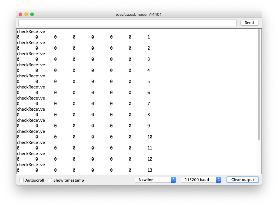
Open the Serial Monitor of Arduino IDE by click Tool-> Serial Monitor. Or tap the ctrl+shift+m key at the same time. Set the baud rate to 115200. The result should be like:

Or you can use python-can to send data:
Python code is as follows:
import time
import can

bustype = 'socketcan_native'
channel = 'can0'

def producer(id):
    """:param id: Spam the bus with messages including the data id."""
    bus = can.interface.Bus(channel=channel, bustype=bustype)
    for i in range(10):
        msg = can.Message(arbitration_id=0xc0ffee, data=[id, i, 0, 1, 3, 1, 4, 1], extended_id=False)
        bus.send(msg)
    # Issue #3: Need to keep running to ensure the writing threads stay alive. ?
    time.sleep(1)

producer(10)
uninstall CAN-HAT
If you want to uninstall this CAN-HAT, just run the following code:
pi@raspberrypi:~/seeed-linux-dtoverlays/modules/CAN-HAT $ sudo ./uninstall.sh
...
------------------------------------------------------
Please reboot your raspberry pi to apply all settings
Thank you!
------------------------------------------------------
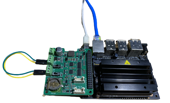
Using CAN-BUS Shiled with Jetson Nano
Now the CAN-BUS Shiled also supports the Jetson Nano Platform but there are some limitations based on different versions of hardware. Please refer to the Version Declare if you are using the Jetson Nano Platfrom!
- Clone the Repo:
git clone https://github.com/Seeed-Studio/seeed-linux-dtoverlays
- Build dtbo & driver:
cd seeed-linux-dtoverlays
export CUSTOM_MOD_LIST="CAN-HAT"; make all_jetsonnano
- Install the Driver:
sudo -E make install_jetsonnano
- Install dtbo:
sudo cp overlays/jetsonnano/2xMCP2518FD-spi0.dtbo /boot
sudo /opt/nvidia/jetson-io/config-by-hardware.py -n "Seeed 2xMCP2518FD"
sudo reboot
Now you can also run the dmesg | grep spi and ifconfig -a to check if the CAN-BUS initialised properly. Depending on your hardware, you should be able to see can0 or both can0 and can1.
The hardware used here is the latest 2-Channel CAN FD Master Hat for RPi which supports two channels on Jetson Nano Platform, if you have older versions then you will only have single channel can0.
qqq@jetson-qqq:~$ dmesg | grep spi
[   10.867712] mcp25xxfd spi0.0 can0: MCP2518FD rev0.0 (-RX_INT -MAB_NO_WARN +CRC_REG +CRC_RX +CRC_TX +ECC -HD m:20.00MHz r:18.50MHz e:0.00MHz) successfully initialized.
[   10.879487] mcp25xxfd spi0.1 can1: MCP2518FD rev0.0 (-RX_INT -MAB_NO_WARN +CRC_REG +CRC_RX +CRC_TX +ECC -HD m:20.00MHz r:18.50MHz e:0.00MHz) successfully initialized.

qqq@jetson-qqq:~$ ifconfig -a
can0: flags=128<NOARP>  mtu 16
        unspec 00-00-00-00-00-00-00-00-00-00-00-00-00-00-00-00  txqueuelen 10  (UNSPEC)
        RX packets 0  bytes 0 (0.0 B)
        RX errors 0  dropped 0  overruns 0  frame 0
        TX packets 0  bytes 0 (0.0 B)
        TX errors 0  dropped 0 overruns 0  carrier 0  collisions 0
        device interrupt 112

can1: flags=128<NOARP>  mtu 16
        unspec 00-00-00-00-00-00-00-00-00-00-00-00-00-00-00-00  txqueuelen 10  (UNSPEC)
        RX packets 0  bytes 0 (0.0 B)
        RX errors 0  dropped 0  overruns 0  frame 0
        TX packets 0  bytes 0 (0.0 B)
        TX errors 0  dropped 0 overruns 0  carrier 0  collisions 0
        device interrupt 114
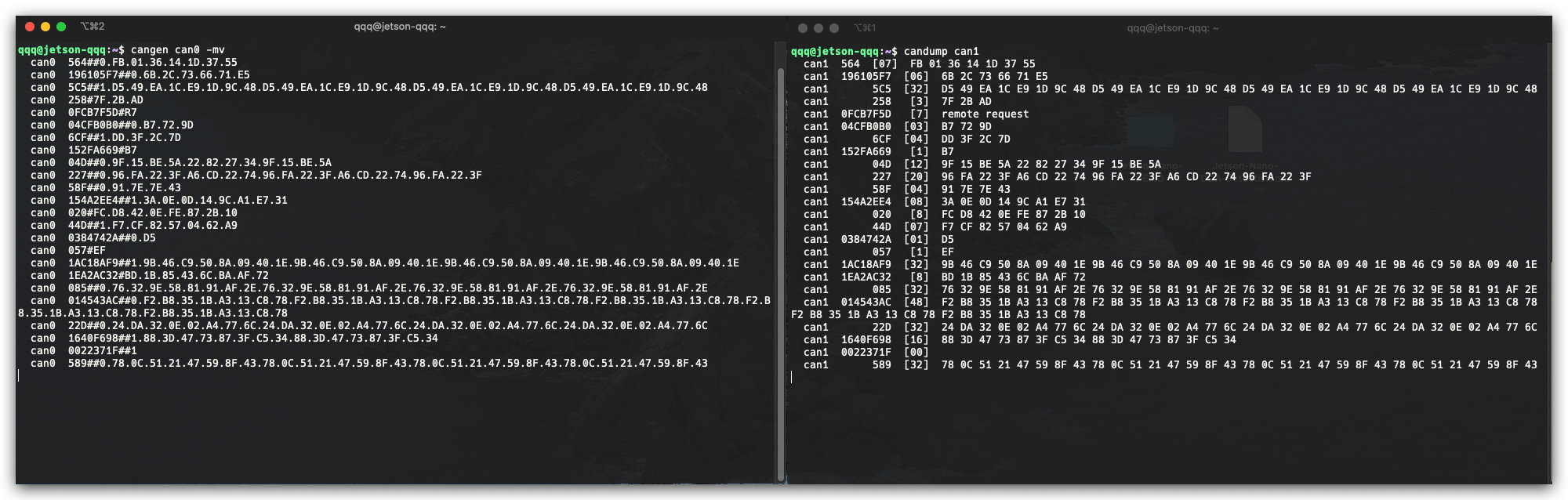
Testing
NOTE: Using 2-Channel CAN FD Master Hat for RPi as hardware here.
You may also connect the channels as follow to test:
0_L <===> 1_L
0_H <===> 1_H
Open two terminal windows and enter the following commands in the Windows to test can fd protocol.
#send data
cangen can0 -mv
#dump data
candump can1
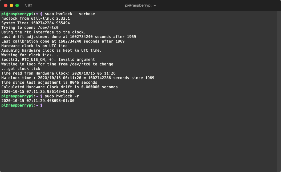
Built-in RTC Usage
The latest 2-Channel CAN FD Master Hat for RPi also has an on-board RTC. Follow though to install the RTC drivers on Raspberry Pi:
- Update Raspberry Pi and Reboot:
sudo apt update
sudo apt upgrade
sudo reboot
- Instsall Dependencies
sudo apt install i2c-tools build-essential raspberrypi-kernel-headers
- Download the driver:
curl -O -L https://github.com/dresden-elektronik/raspbee2-rtc/archive/master.zip
unzip master.zip
- Compile the RTC Kernel module
cd raspbee2-rtc-master
make
- Install the RTC Kernel module
sudo make install
sudo reboot
- Configure system time to the RTC module
sudo hwclock --systohc
- Test that the RTC is working
sudo hwclock --verbose
Now you can read the RTC time using the following command:
sudo hwclock -r
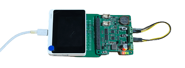
Using with Wio Terminal
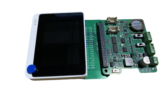
Apart from using the CAN-BUS Pi Hat with SBCs, now you can also use it the Wio Terminal (Arduino Compatitable Board)! And develop CAN related projects on MCU!
Please check the following wikis to find out more about Wio Terminal:
Hardware Required
For testing purpose, you may also prepare some other CAN-BUS devs components, for this example we are using the following:
- CAN-BUS Shield V2 adopts MCP2515 and MCP2551 + Arduino Board
Install the Seeed_Arduino_CAN Arduino Library
Please make sure you have installed Seeed SAMD Board library and updated to the latest version!
Visit the Seeed_Arduino_CAN repositories and download the entire repo to your local drive.
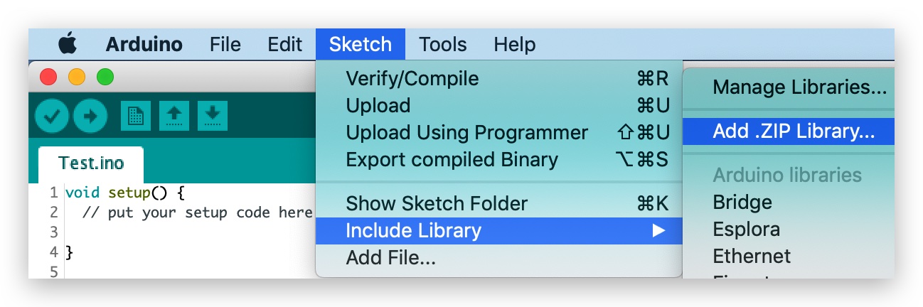
Now, the Seeed_Arduino_CAN library can be installed to the Arduino IDE. Open the Arduino IDE, and click
sketch->Include Library->Add .ZIP Library, and choose theSeeed_Arduino_CANfile that you've have just downloaded.
Send Example Code
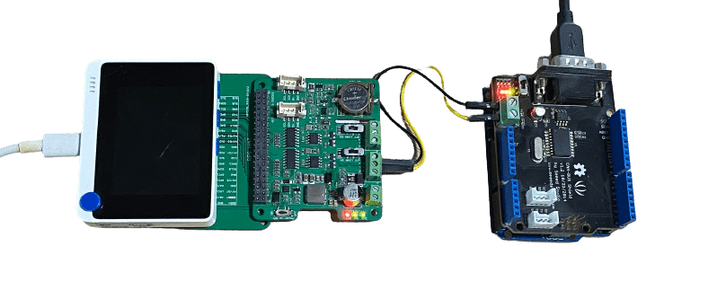
This is an example of using the 2-Channel CAN-BUS(FD) Shield for Raspberry Pi (MCP2518FD) with Wio Terminal to send CAN-BUS data to another CAN-BUS device(In this case, it's CAN-BUS Shield V2 adopts MCP2515 and MCP2551 + Arduino Uno)
Hardware Connection
Connect 2-Channel CAN-BUS(FD) Shield for Raspberry Pi (MCP2518FD)'s
Channel 0 L-> CAN-BUS Shield V2'sCANLConnect 2-Channel CAN-BUS(FD) Shield for Raspberry Pi (MCP2518FD)'s
Channel 0 H-> CAN-BUS Shield V2'sCANHConnect 2-Channel CAN-BUS(FD) Shield for Raspberry Pi (MCP2518FD) with Wio Terminal using 40 Pin Raspberry Pi Hat Adapter Board For Wio Terminal.
- Code for Arduino Uno + CAN-BUS Shield V2
#include <SPI.h>
#include "mcp2515_can.h"

/*SAMD core*/
#ifdef ARDUINO_SAMD_VARIANT_COMPLIANCE
    #define SERIAL SerialUSB
#else
    #define SERIAL Serial
#endif

const int SPI_CS_PIN = 9;
mcp2515_can CAN(SPI_CS_PIN);

unsigned char len = 0;
unsigned char buf[8];

void setup() {
    SERIAL.begin(115200);
    while (!SERIAL) {
        ; // wait for serial port to connect. Needed for native USB port only
    }
    while (CAN_OK != CAN.begin(CAN_500KBPS)) {             // init can bus : baudrate = 500k
        // init can bus : baudrate = 500k
        SERIAL.println("CAN BUS Shield init fail");
        SERIAL.println(" Init CAN BUS Shield again");
        delay(100);
    }
    SERIAL.println("CAN BUS Shield init ok!");
}

void loop() {
        // iterate over all pending messages
        // If either the bus is saturated or the MCU is busy,
        // both RX buffers may be in use and reading a single
        // message does not clear the IRQ conditon.
        while (CAN_MSGAVAIL == CAN.checkReceive()) {
            // read data,  len: data length, buf: data buf
            SERIAL.println("checkReceive");
            CAN.readMsgBuf(&len, buf);

            // print the data
            for (int i = 0; i < len; i++) {
                SERIAL.print(buf[i]); SERIAL.print("\t");
            }
            SERIAL.println();
        }
}
- Code for Wio Terminal + 2-Channel CAN-BUS(FD) Shield for Raspberry Pi (MCP2518FD)
#include <SPI.h>
#include "mcp2518fd_can.h"
/*SAMD core*/
#ifdef ARDUINO_SAMD_VARIANT_COMPLIANCE
#define SERIAL SerialUSB
#else
#define SERIAL Serial
#endif
// Set SPI CS Pin according to your hardware
// For Wio Terminal w/ MCP2518FD RPi Hat:
// Channel 0 SPI_CS Pin: BCM 8
// Channel 1 SPI_CS Pin: BCM 7
// Interupt Pin: BCM25
// *****************************************
// For Arduino MCP2515 Hat:
// SPI_CS Pin: D9
const int SPI_CS_PIN = BCM8;
mcp2518fd CAN(SPI_CS_PIN); // Set CS pin
void setup() {
SERIAL.begin(115200);
while(!Serial){};
while (0 != CAN.begin((byte)CAN_500K_1M)) { // init can bus : baudrate = 500k
SERIAL.println("CAN BUS Shield init fail");
SERIAL.println(" Init CAN BUS Shield again");
delay(100);
}
SERIAL.println("CAN BUS Shield init ok!");
}
unsigned char stmp[8] = {0, 0, 0, 0, 0, 0, 0, 0};
void loop() {
// send data: id = 0x00, standrad frame, data len = 8, stmp: data buf
stmp[7] = stmp[7] + 1;
if (stmp[7] == 100) {
stmp[7] = 0;
stmp[6] = stmp[6] + 1;
if (stmp[6] == 100) {
stmp[6] = 0;
stmp[5] = stmp[6] + 1;
}
}
CAN.sendMsgBuf(0x00, 0, 8, stmp);
delay(100); // send data per 100ms
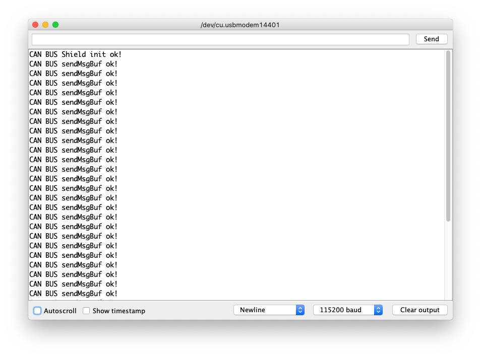
SERIAL.println("CAN BUS sendMsgBuf ok!");
}
Recevice Example Code
This is an example of using the 2-Channel CAN-BUS(FD) Shield for Raspberry Pi (MCP2518FD) with Wio Terminal to receive CAN-BUS data from another CAN-BUS device(In this case, it's CAN-BUS Shield V2 adopts MCP2515 and MCP2551 + Arduino Uno)
Hardware Connection
Same conncection as the above Send Example.
- Code for Arduino Uno + CAN-BUS Shield V2
#include <SPI.h>
#include "mcp2515_can.h"

/*SAMD core*/
#ifdef ARDUINO_SAMD_VARIANT_COMPLIANCE
    #define SERIAL SerialUSB
#else
    #define SERIAL Serial
#endif

const int SPI_CS_PIN = 9;
mcp2515_can CAN(SPI_CS_PIN); // Set CS pin


void setup() {
    SERIAL.begin(115200);
    while(!Serial){};

    while (CAN_OK != CAN.begin(CAN_500KBPS)) {             // init can bus : baudrate = 500k
        SERIAL.println("CAN BUS Shield init fail");
        SERIAL.println(" Init CAN BUS Shield again");
        delay(100);
    }
    SERIAL.println("CAN BUS Shield init ok!");
}

unsigned char stmp[8] = {0, 0, 0, 0, 0, 0, 0, 0};
void loop() {
    // send data:  id = 0x00, standrad frame, data len = 8, stmp: data buf
    stmp[7] = stmp[7] + 1;
    if (stmp[7] == 100) {
        stmp[7] = 0;
        stmp[6] = stmp[6] + 1;

        if (stmp[6] == 100) {
            stmp[6] = 0;
            stmp[5] = stmp[6] + 1;
        }
    }

    CAN.sendMsgBuf(0x00, 0, 8, stmp);
    delay(100);                       // send data per 100ms
    SERIAL.println("CAN BUS sendMsgBuf ok!");
}
- Code for Wio Terminal + 2-Channel CAN-BUS(FD) Shield for Raspberry Pi (MCP2518FD)
#include <SPI.h>
#include "mcp2518fd_can.h"

/*SAMD core*/
#ifdef ARDUINO_SAMD_VARIANT_COMPLIANCE
    #define SERIAL SerialUSB
#else
    #define SERIAL Serial
#endif

// Set SPI CS Pin according to your hardware
// For Wio Terminal w/ MCP2518FD RPi Hat:
// Channel 0 SPI_CS Pin: BCM 8
// Channel 1 SPI_CS Pin: BCM 7
// Interupt Pin: BCM25
// *****************************************
// For Arduino MCP2515 Hat:
// SPI_CS Pin: D9

const int SPI_CS_PIN = BCM8;
mcp2518fd CAN(SPI_CS_PIN);

unsigned char len = 0;
unsigned char buf[8];

void setup() {
    SERIAL.begin(115200);
    while (!SERIAL) {
        ; // wait for serial port to connect. Needed for native USB port only
    }
    while (0 != CAN.begin((byte)CAN_500K_1M)) {            // init can bus : baudrate = 500k
        SERIAL.println("CAN BUS Shield init fail");
        SERIAL.println(" Init CAN BUS Shield again");
        delay(100);
    }
    SERIAL.println("CAN BUS Shield init ok!");
}

void loop() {
        // iterate over all pending messages
        // If either the bus is saturated or the MCU is busy,
        // both RX buffers may be in use and reading a single
        // message does not clear the IRQ conditon.
        while (CAN_MSGAVAIL == CAN.checkReceive()) {
            // read data,  len: data length, buf: data buf
            SERIAL.println("checkReceive");
            CAN.readMsgBuf(&len, buf);

            // print the data
            for (int i = 0; i < len; i++) {
                SERIAL.print(buf[i]); SERIAL.print("\t");
            }
            SERIAL.println();
        }
}
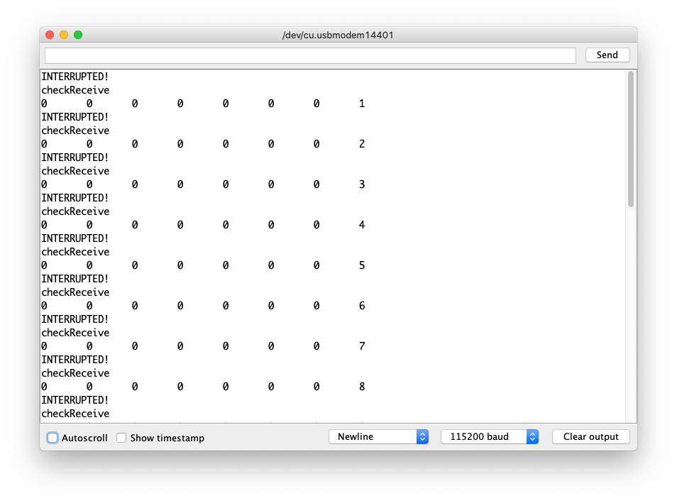
Receive using Interrupt Example Code
This is an example of using the 2-Channel CAN-BUS(FD) Shield for Raspberry Pi (MCP2518FD) with Wio Terminal to receive CAN-BUS data from another CAN-BUS device(In this case, it's CAN-BUS Shield V2 adopts MCP2515 and MCP2551 + Arduino Uno). To make it more reliable, here used interupt to trigger the incoming data flow.
Hardware Connection
- Code for Arduino Uno + CAN-BUS Shield V2
#include <SPI.h>
#include "mcp2515_can.h"

/*SAMD core*/
#ifdef ARDUINO_SAMD_VARIANT_COMPLIANCE
    #define SERIAL SerialUSB
#else
    #define SERIAL Serial
#endif

const int SPI_CS_PIN = 9;
mcp2515_can CAN(SPI_CS_PIN); // Set CS pin

void setup() {
    SERIAL.begin(115200);
    while(!Serial){};

    while (CAN_OK != CAN.begin(CAN_500KBPS)) {             // init can bus : baudrate = 500k
        SERIAL.println("CAN BUS Shield init fail");
        SERIAL.println(" Init CAN BUS Shield again");
        delay(100);
    }
    SERIAL.println("CAN BUS Shield init ok!");
}

unsigned char stmp[8] = {0, 0, 0, 0, 0, 0, 0, 0};
void loop() {
    // send data:  id = 0x00, standrad frame, data len = 8, stmp: data buf
    stmp[7] = stmp[7] + 1;
    if (stmp[7] == 100) {
        stmp[7] = 0;
        stmp[6] = stmp[6] + 1;

        if (stmp[6] == 100) {
            stmp[6] = 0;
            stmp[5] = stmp[6] + 1;
        }
    }

    CAN.sendMsgBuf(0x00, 0, 8, stmp);
    delay(100);                       // send data per 100ms
    SERIAL.println("CAN BUS sendMsgBuf ok!");
}
Code for Wio Terminal + 2-Channel CAN-BUS(FD) Shield for Raspberry Pi (MCP2518FD)
#include <SPI.h>
#include "mcp2518fd_can.h"

/*SAMD core*/
#ifdef ARDUINO_SAMD_VARIANT_COMPLIANCE
    #define SERIAL SerialUSB
#else
    #define SERIAL Serial
#endif

// Set SPI CS Pin according to your hardware
// For Wio Terminal w/ MCP2518FD RPi Hat:
// Channel 0 SPI_CS Pin: BCM 8
// Channel 1 SPI_CS Pin: BCM 7
// Interupt Pin: BCM25
// *****************************************
// For Arduino MCP2515 Hat:
// SPI_CS Pin: D9

const int SPI_CS_PIN = BCM8;
const int CAN_INT_PIN = BCM25;

mcp2518fd CAN(SPI_CS_PIN);

unsigned char flagRecv = 0;
unsigned char len = 0;
unsigned char buf[8];

void MCP2515_ISR() {
    Serial.println("INTERUPTED!");
    flagRecv = 1;
}

void setup() {
    SERIAL.begin(115200);
    while (!SERIAL) {
        ; // wait for serial port to connect. Needed for native USB port only
    }
    pinMode(CAN_INT_PIN, INPUT);
    attachInterrupt(digitalPinToInterrupt(CAN_INT_PIN), MCP2515_ISR, FALLING); // start interrupt

    while (0 != CAN.begin((byte)CAN_500K_1M)) {            // init can bus : baudrate = 500k
        SERIAL.println("CAN BUS Shield init fail");
        SERIAL.println(" Init CAN BUS Shield again");
        delay(100);
    }
    SERIAL.println("CAN BUS Shield init ok!");
}

void loop() {
  if (flagRecv) // Triggered Interrupt
  {
    flagRecv = 0;
  // iterate over all pending messages
  // If either the bus is saturated or the MCU is busy,
  // both RX buffers may be in use and reading a single
  // message does not clear the IRQ conditon.
    while (CAN_MSGAVAIL == CAN.checkReceive()) {
        // read data,  len: data length, buf: data buf
      SERIAL.println("checkReceive");
      CAN.readMsgBuf(&len, buf);

        // print the data
      for (int i = 0; i < len; i++) {
        SERIAL.print(buf[i]); SERIAL.print("\t");
        }
      SERIAL.println();
    }
  }
}
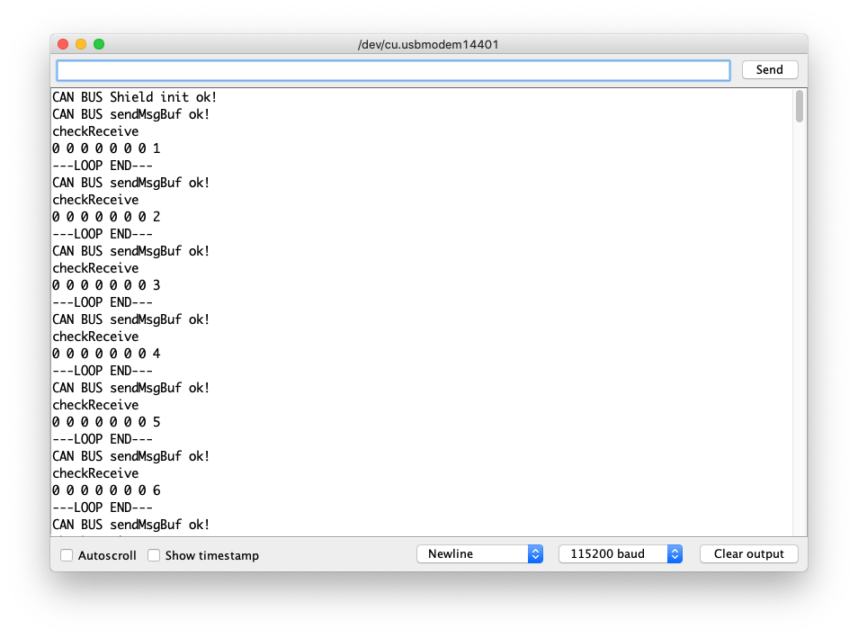
Self Send-Receive Example Code
This is an example of sending and receivce CAN-BUS data on its own using the 2-Channel CAN-BUS(FD) Shield for Raspberry Pi (MCP2518FD).
Hardware Connection
Connect 2-Channel CAN-BUS(FD) Shield for Raspberry Pi (MCP2518FD)'s
Channel 0 L-> 2-Channel CAN-BUS(FD) Shield for Raspberry Pi (MCP2518FD)'sChannel 1 LConnect 2-Channel CAN-BUS(FD) Shield for Raspberry Pi (MCP2518FD)'s
Channel 0 H-> 2-Channel CAN-BUS(FD) Shield for Raspberry Pi (MCP2518FD)'sChannel 1 H
#include <SPI.h>
#include "mcp2518fd_can.h"

/*SAMD core*/
#ifdef ARDUINO_SAMD_VARIANT_COMPLIANCE
    #define SERIAL SerialUSB
#else
    #define SERIAL Serial
#endif

// Set SPI CS Pin according to your hardware
// For Wio Terminal w/ MCP2518FD RPi Hat:
// Channel 0 SPI_CS Pin: BCM 8
// Channel 1 SPI_CS Pin: BCM 7
// Interupt Pin: BCM25
// *****************************************
// For Arduino MCP2515 Hat:
// SPI_CS Pin: D9

const int SPI_CS_PIN_SEND = BCM8;
const int SPI_CS_PIN_RECEIVE = BCM7;

mcp2518fd CAN_SEND(SPI_CS_PIN_SEND);
mcp2518fd CAN_RECEIVE(SPI_CS_PIN_RECEIVE);

unsigned char len = 0;
unsigned char buf[8];

void setup() {
    SERIAL.begin(115200);
    while(!Serial); // wait for Serial

    if (CAN_SEND.begin((byte)CAN_500K_1M) != 0 || CAN_RECEIVE.begin((byte)CAN_500K_1M) != 0) {
      Serial.println("CAN-BUS initiliased error!");
      while(1);
    }

    SERIAL.println("CAN BUS Shield init ok!");
}

unsigned char stmp[8] = {0, 0, 0, 0, 0, 0, 0, 0};
void loop() {
    // send data:  id = 0x00, standrad frame, data len = 8, stmp: data buf
    stmp[7] = stmp[7] + 1;
    if (stmp[7] == 100) {
        stmp[7] = 0;
        stmp[6] = stmp[6] + 1;

        if (stmp[6] == 100) {
            stmp[6] = 0;
            stmp[5] = stmp[6] + 1;
        }
    }

    CAN_SEND.sendMsgBuf(0x00, 0, 8, stmp);
    delay(100);                       // send data per 100ms
    SERIAL.println("CAN BUS sendMsgBuf ok!");

    // ---------------------

    if (CAN_MSGAVAIL == CAN_RECEIVE.checkReceive()) {
    // read data,  len: data length, buf: data buf
      SERIAL.println("checkReceive");
      CAN_RECEIVE.readMsgBuf(&len, buf);
    // print the data
    for (int i = 0; i < len; i++) {
        SERIAL.print(buf[i]); SERIAL.print(" ");
    }
    SERIAL.println();
    }
    SERIAL.println("---LOOP END---");
}
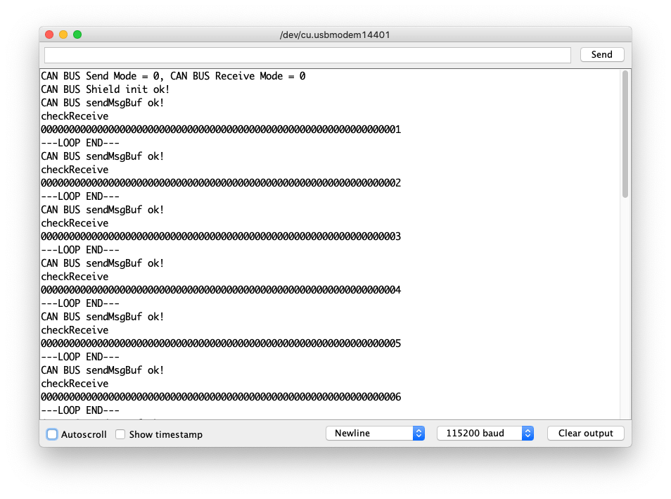
Sending FD Example Code
This is an example of sending and receivce CAN-BUS data (up to 64 bit) using the FD Protocol on its own using the 2-Channel CAN-BUS(FD) Shield for Raspberry Pi (MCP2518FD).
Hardware Connection
Same connection as the Self Send-Receive Example.
#include <SPI.h>
#include "mcp2518fd_can.h"

/*SAMD core*/
#ifdef ARDUINO_SAMD_VARIANT_COMPLIANCE
    #define SERIAL SerialUSB
#else
    #define SERIAL Serial
#endif

// Set SPI CS Pin according to your hardware
// For Wio Terminal w/ MCP2518FD RPi Hat:
// Channel 0 SPI_CS Pin: BCM 8
// Channel 1 SPI_CS Pin: BCM 7
// Interupt Pin: BCM25
// *****************************************
// For Arduino MCP2515 Hat:
// SPI_CS Pin: D9

const int SPI_CS_PIN_SEND = BCM8;
const int SPI_CS_PIN_RECEIVE = BCM7;

mcp2518fd CAN_SEND(SPI_CS_PIN_SEND);
mcp2518fd CAN_RECEIVE(SPI_CS_PIN_RECEIVE);

void setup() {
    SERIAL.begin(115200);
    while(!Serial); // wait for Serial
    CAN_SEND.setMode(0);
    CAN_RECEIVE.setMode(0);

    if (CAN_SEND.begin((byte)CAN_500K_1M) != 0 || CAN_RECEIVE.begin((byte)CAN_500K_1M) != 0) {
      Serial.println("CAN-BUS initiliased error!");
      while(1);
    }
    byte send_mode = CAN_SEND.getMode();
    byte receive_mode = CAN_RECEIVE.getMode();
    SERIAL.printf("CAN BUS Send Mode = %d, CAN BUS Receive Mode = %d\n\r",send_mode, receive_mode);
    SERIAL.println("CAN BUS Shield init ok!");
}

unsigned char stmp[64] = {0};
unsigned char len = 0;
unsigned char buf[64];

void loop() {
    stmp[63] = stmp[63] + 1;
    if (stmp[63] == 100) {
        stmp[63] = 0;
        stmp[62] = stmp[62] + 1;

        if (stmp[62] == 100) {
            stmp[62] = 0;
            stmp[61] = stmp[62] + 1;
        }
    }

    CAN_SEND.sendMsgBuf(0x00, 0, 15, stmp);
    delay(100);                       // send data per 100ms
    SERIAL.println("CAN BUS sendMsgBuf ok!");

    // ---------------------

    if (CAN_MSGAVAIL == CAN_RECEIVE.checkReceive()) {
    // read data,  len: data length, buf: data buf
      SERIAL.println("checkReceive");
      CAN_RECEIVE.readMsgBuf(&len, buf);
    // print the data
    for (int i = 0; i < len; i++) {
        SERIAL.print(buf[i]); SERIAL.print(" ");
    }
    SERIAL.println();
    }
    SERIAL.println("---LOOP END---");
}
Schematic Online Viewer
Resources
- [PDF] 2-Channel CAN-BUS(FD) Shield for Raspberry Pi (MCP2518FD) Schematics
- [ZIP] 2-Channel CAN-BUS(FD) Shield for Raspberry Pi Schematic file
- [ZIP] 2-Channel CAN FD Master Hat for RPi Schematic file
- [PDF] MCP2517 Datasheet
- [PDF] MCP2557 Datasheet
Tech Support & Product Discussion
Thank you for choosing our products! We are here to provide you with different support to ensure that your experience with our products is as smooth as possible. We offer several communication channels to cater to different preferences and needs.