Seeeduino Lotus

Seeeduino Lotus is an ATMEGA328 Microcontroller development board. It is a combination of Seeeduino and Base Shield. Seeeduino Lotus v1.0 uses an Atmel ATMEGA328P-MU and CH340. ATMEGA328P-MU is a high performance, low power AVR 8-Bit Microcontroller. CH340 is a USB bus converter chip that can realize a USB to serial interface. Seeeduino Lotus v1.1 replace CH340 with CP2102N to enable the compatibilty with MAC, there is nothing other change compared to Seeeduino Lotus v1.0. Seeeduino Lotus has 14 digital input/outputs (6 of which can output PWM) and 7 analog input/outputs, a micro USB connection, an ICSP header, 12 Grove connections, a reset button.
Seeeduino Lotus 1.0 works at Windows Operating System ONLY. Seeeduino Lotus 1.1 works with Window and Mac.
Version
| Revision | Descriptions | Release | How to buy |
|---|---|---|---|
| v1.0 | Initial public release (beta) | Jul 22, 2014 |  |
| v1.1 | Replace CH340 with CP2102N to enable the compatibilty with MAC | Dec 22,2016 | |
Application Ideas
- DIY
- IoT and Smart Home
- Robot
- Learning
- Toy
Here is some funny project for your reference.
| Car Controlled by Track Ball | FM Receiver | Make a Wooden Gun |
|---|---|---|
 |  |  |
| Make it Now | Make it Now | Make it Now |
Feature
- Fully compatible with Arduino UNO
- ATmega328 microcontroller
- 12 on-board Grove connectors
- 14 Digital I/O Pins (6 PWM outputs)
- 6 Analog Inputs
- ISP Header
- Arduino UNO-R3 Shield Compatible
- Micro USB programming and power supply
- 5V Operating Voltage
Specification
| Item | Value |
|---|---|
| Microcontroller | ATmega328P-MU |
| Operating Voltage | 5V |
| Digital I/O Pins | 14 |
| PWM Channels | 6 |
| Analog Input Channels | 7 |
| DC Current per I/O Pin | 40 mA |
| Flash Memory | 32 KB |
| RAM | 2 KB |
| EEPROM | 1 KB |
| Clock Speed | 16 MHz |
Hardware Overview
The images below show an overview of Seeeduino Lotus hardware features. The pin-out and alternate functions of various pins of Seeeduino Lotus are shown in the pin-out diagram. This could be used as a quick reference.
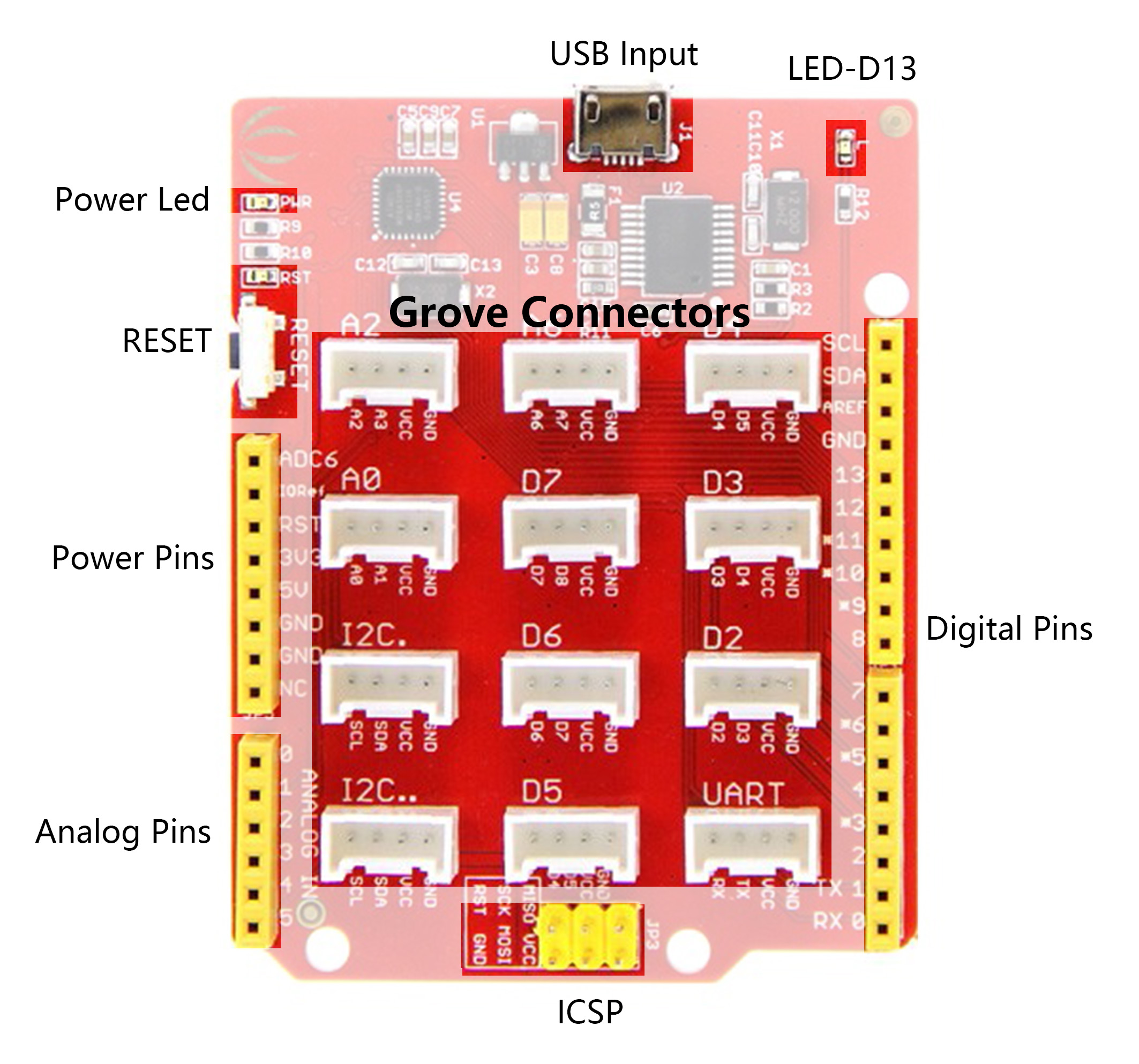
- LED-D13 An LED is connected to D13 pin of the board. This can be used as an on-board LED indicator for programs/sketches.
- USB Input USB Port is used to connect the board to your PC for programming and for powering up. Micro USB is the ubiquitous version of USB, found in most Android phones, and other devices. You probably have dozens of these cables laying around your house.
- Reset This button is conveniently placed on the side to allow you to reset the Seeeduino board even when a shield is placed on top. This is not the case in other Arduino boards where the button is placed on top making it hard to access.
- Power Pins & Analog Pins Just like the extra Digital header pads, these extra connections are something we have personally come to realize people need in their projects, especially the power connections if you want to power more than one sensor/device without the use of a breadboard.
- Grove Connectors SeeedStudio has a variety of sensors/devices that can make use of this Analog, Digital,I2C and UART connection. In addition, we sell independent Grove connectors to help you make our own sensor connections.
- ICSP This is the ICSP connection for the ATmega328P, it is located in the standard ICSP/SPI position for Arduino Uno, Due, Mega, and Leonardo compatible hardware (e.g. shields) that may use this connector. The SPI pins in this port: MISO, SCK, and MOSI, are also connected to digital pins 12, 13, and 11 respectively just like those of the Arduino Uno.
- USB 2 Uart Pinout of USB-2-Uart. These pads can be used to interact with other UART devices by putting the on-board ATmega328 in reset mode. This makes Seeeduino Lotus to be used a USB2UART utility board.
Take gentle care in handling micro USB socket, or you might break the socket off.
Install the Driver
First of all, you need to:
-
Get a Micro-USB cable You need a Micro-USB cable first; the data cable of an Android Phone will do fine. If you can't find one, you can buy one here.
-
Connect the board Connect the Arduino board to your computer using the USB cable. The green power LED (labelled PWR) should go on.
This CH340 driver (Seeeduino_Lotus V1.0) is available for Windows XP, Windows Vista, Windows 7, Windows 8/8.1 and Windows 10.

Double click on the driver and Install it.

This CP2102N driver (Seeeduino_Lotus V1.1) is available for Windows XP, Windows Vista, Windows 7, Windows 8/8.1, Windows 10 and Mac.
Getting Started
This part is based on Arduino 1.6.9 under Windows 10.
First of all, you need to Install an Arduino Software.

Launch the Arduino application
Double-click the Arduino application (arduino.exe) you have previously downloaded.
If the Arduino Software loads in a different language, you can change it in the preferences dialog. See the Arduino Software (IDE) page for details.
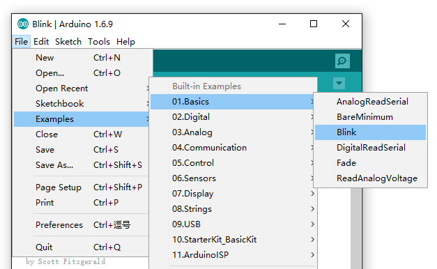
Open the Blink example
Open the LED blink example sketch: File > Examples >01.Basics > Blink.
Add Seeeduino Lite to your Arduino IDE
There is no Seeeduino Lite option in the boards of your Arduino IDE, click on How to Add Seeed boards to Arduino IDE for the instruction.
Select your board You'll need to select the entry in the Tools > Board menu that corresponds to your Arduino. Selecting a Seeeduino Lotus.

Select your serial port Select the serial device of the Arduino board from the Tools | Serial Port menu. This is likely to be COM3 or higher (COM1 and COM2 are usually reserved for hardware serial ports). To find out, you can disconnect your Arduino board and re-open the menu; the entry that disappears should be the Arduino board. Reconnect the board and select that serial port.

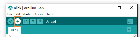
Upload the program Now, simply click the "Upload" button in the environment. Wait a few seconds and if the upload is successful, the message "Done uploading." will appear in the status bar.
A few seconds after the upload finishes, you should see the pin 13 (L) LED on the board start to blink (in orange). If it does, congratulations! You've gotten Arduino up-and-running. If you have problems, please see the troubleshooting suggestions.
Seeeduino Lotus v1.0 Schematic Online Viewer
Seeeduino Lotus v1.1 Schematic Online Viewer
Resources
-
Schematic
-
Datasheet
-
References
FAQ
Q1. What's the different between Arduino UNO and Seeeduino Lotus
Seeeduino Lotus is fully compatible with Arduino UNO. And Seeeduino Lotus has 12 Grove connectors, which makes it convenient to create your demo with Seeed Studio Grove Modules. What's more, Seeeduino Lotus uses a micro USB to power and program.
Q2. I can't upload my sketch to Seeeduino Lotus
Please check,
- If the Power LED on
- If you choose the right Port and Board (Seeeduino Lotus)
- Close and reopen Arduino IDE and try again
Project
The Da Vinci Code The work combines art and electronics. The art part makes the skeleton and consists of 11 layers of medium density fiberboard.
The Little Universe, a Gesture-Controlled Floor Lamp The Little Universe is a gesture-controlled floor lamp with three wooden legs and an artistic lamp head.
Tech Support & Product Discussion
Thank you for choosing our products! We are here to provide you with different support to ensure that your experience with our products is as smooth as possible. We offer several communication channels to cater to different preferences and needs.