Seeeduino Crypto (ATmega4809 ECC608)

Seeeduino Crypto is made for encryption. It is based on the high performance ATmega4809 and microchip ECC608 encryption chip.With the help of ECC608 encryption chip, you can experience I2C encryption and other encrypted communication.
In addition to encryption, Seeeduino Crypto has the same functions as Seeeduino V4.2 / Arduino Uno Rev3. It has rich interface resources, including 6 analog input pins, 14 digital I/ o-5s for PWM output, with 2 Grove I2C ports and 1 Grove UART port. Just plug it in and use hundreds of sensors and actuators.
The control solution Seeeduino Crypto is the same as ARDUINO UNO WIFI REV2. The difference is that Seeeduino Crypto does not have onboard WIFI. You can add an Arduino wifi module if necessary. Correspondingly, the price of Seeeduino Crypto is less than half of ARDUINO UNO WIFI REV2.
This product allows users to experience the encryption mode of I2C communication with great plasticity.

Features
High-performance ATmega4809 microcontroller
High-securitycryptographic Chip ECC608, supports SHA-256 & HMAC Hash / AES-128
2 Grove I2C + 1 Grove UART, easy to prototype
Type C power supply + data transmit
Specification
| Item | Detail |
|---|---|
| Chip | Microcontroller: ATMEGA4809-AFR / Encryption: ECC608 |
| Clock Speed | 16Mhz |
| I/O Resource | Analog Input Channels: 6 /Digital I/O Pins: 14 / PWM Channels: 5 |
| Peripheral Interface | 2 Grove I2C Port / 1 Grove UART Port / 1 ICSP Interface /1 USB Type C data port |
| Operating Voltage | 5V |
| Power Supply | 5V USB Type C / 8 -15 V DC Jack Input |
Hardware Overview

Type C It is the board Type C interface, connected to the PC end, used as power supply and download.
LED RX / LED TX Serial communication indicator LEDS TX,RX, Convenient for users to know the receiving and receiving status of serial communication.
DC Power Jack The input voltage is 8v-15v.
Reset Button and Reset LED Used to reset the board, when reset, the reset lamp will flicker.
Power LED The system power indicator.
ATMEGA32U4-MU Chip The chip used as a USB to UPDI download is connected to the master MCU atmega4809-afr to burn the program to the master MCU.
ATECC608 Encryption Chip An encryption chip for I2C communication.
ATMEGA4809-AFR Chip Onboard MCU, as the main control chip of the system.
Grove Connectors Contains two I2C and a UART standard Grove interface
When using serial port to communicate the output data, there should be a certain delay of more than 25ms, otherwise the serial port may be stuck.
Getting Started
This part is based on Arduino 1.8.10 under Windows 10.
First of all, you need to Install an Arduino Software.

Launch the Arduino application
Double-click the Arduino application (arduino.exe) you have previously downloaded.
If the Arduino Software loads in a different language, you can change it in the preferences dialog. See the [Arduino Software (IDE) page](https://www.arduino.cc/en/Guide/Environment#languages) for details.
Open the Blink example
Open the LED blink example sketch: File > Examples >01.Basics > Blink.

Add Seeeduino to your Arduino IDE
Click on Tools > Board > Boards Manager, you can tap the keyword 'MegaAVR' at the search bar , find Arduino MegaAVR, and Install it.

Select your board
You'll need to select the entry in the Tools > Board menu that corresponds to your Arduino. Selecting a Arduino Uon WIFI Rev2.

Select your serial port
Select the serial device of the Arduino board from the Tools | Serial Port menu. This is likely to be COM3 or higher (COM1 and COM2 are usually reserved for hardware serial ports). To find out, you can disconnect your Arduino board and re-open the menu; the entry that disappears should be the Arduino board. Reconnect the board and select that serial port.

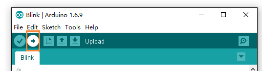
Upload the program
Now, simply click the "Upload" button in the environment. Wait a few seconds and if the upload is successful, the message "Done uploading." will appear in the status bar.
A few seconds after the upload finishes, you should see the pin 13 (L) LED on the board start to blink (in orange). If it does, congratulations! You've gotten Arduino up-and-running. If you have problems, please see the troubleshooting suggestions.
Resources
Schematic
Data Sheet
References
Tech Support & Product Discussion
Thank you for choosing our products! We are here to provide you with different support to ensure that your experience with our products is as smooth as possible. We offer several communication channels to cater to different preferences and needs.