Seeeduino Lotus Cortex-M0+
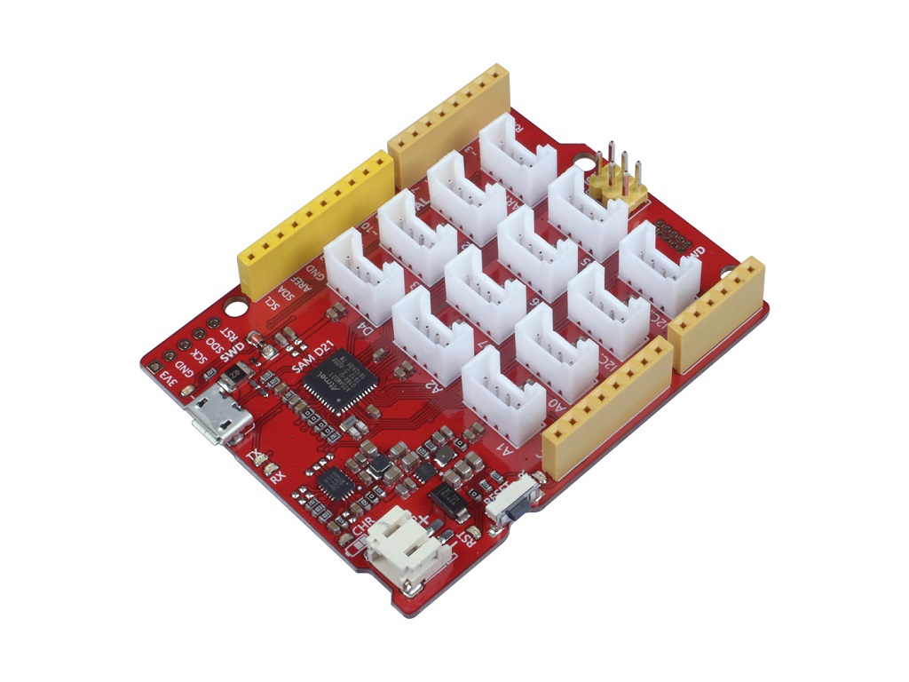
Seeeduino Lotus Cortex-M0+ is an ATMEGA SAM D21 Microcontroller development board. The Atmel® | SMART™ SAM D21 is a series of low-power microcontrollers using the 32-bit ARM® Cortex®-M0+ processor with 256KB Flash and 32KB of SRAM. you can consider the Seeeduino Lotus Cortex-M0+ as a combination of Seeeduino and Base Shield.
Seeeduino Lotus Cortex-M0+ has 14 digital input/outputs (10 of which support PWM) and 6 analog input/outputs, 3 Serial Communication Interface, a micro USB connector, a JST2.0 Li-Po connector, an ICSP header, 12 Grove connectors, a reset button.
Seeeduino Lotus Cortex-M0+ is an upgraded version of Seeeduino Lotus V1.1, it replaces a more powerful chip, optimizes the circuit layout, and the power supply is more stable. Because this chip supports direct USB level output, there is no need to use a serial port to USB chip, like CP2102N. Therefore, one more hardware serial port is available to the user.
Seeeduino Lotus has 14 digital input/outputs (6 of which can output PWM) and 7 analog input/outputs, a micro USB connection, an ICSP header, 12 Grove connections, a reset button.

Version
| Revision | Descriptions | Release | How to buy |
|---|---|---|---|
| v1.0 | Initial public release (beta) | Jul 22, 2014 |  |
| v1.1 | Replace CH340 with CP2102N to enable the compatibilty with MAC | Dec 22,2016 | |
| Seeeduino Lotus Cortex-M0+ | Change the Atmega328 microcontroller chip into SAM D21 / Optimized circuit design, power supply is more stable | October.29, 2018 | |
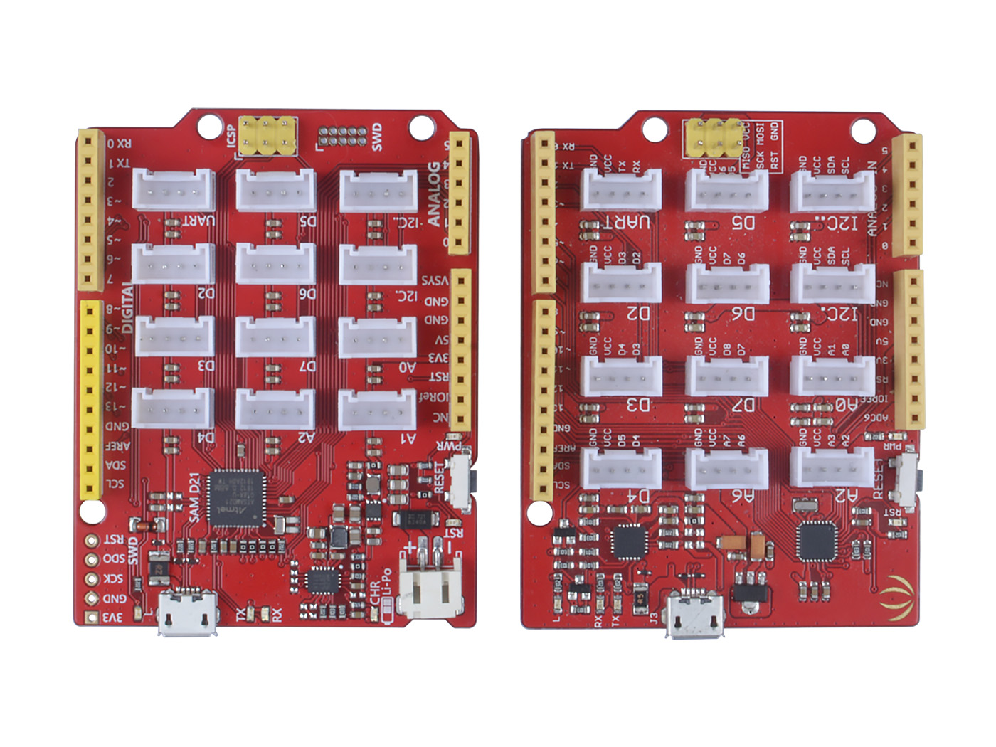
Upgrade Instructions
Compared with Seeeduino Lotus V1.1, the Seeeduino Lotus Cortex-M0+ mainly upgrades in hardware. Please check the figure below.
| Item | Seeeduino Lotus V1.1 | Seeeduino Lotus Cortex-M0+ |
|---|---|---|
| MCU | Atmega328 | SAM D21 |
| UART | 1 | 2 |
| Li-po battery support | NOT | YES |
| PWM PIN | 6 | 10 |
Application Ideas
- DIY
- IoT and Smart Home
- Robot
- Education
Feature
- Fully compatible with Arduino UNO
- ARM® Cortex®-M0+ 32bit 48MHz microcontroller(SAMD21)
- 12 on-board Grove connectors
- 14 Digital I/O Pins (10 PWM outputs)
- 6 Analog Inputs
- Support Power Path Management
- Support micro-usb or Li-Po battery powered
- 2A maximum charging current
- Suitable for low power design
Specification
| Item | Value |
|---|---|
| Microcontroller | SAM D21 |
| Power Input | Micro-USB / JST2.0 |
| Operating Voltage | USB:5V / Lipo:3.5V~4.2V |
| Digital I/O Pins | 14 |
| PWM Channels | 10 |
| Analog Input Channels | 6 |
| DC Current per I/O Pin | 40 mA |
| IO Input Voltage | 3.3V |
| SRAM | 32 KB |
| Flash Memory | 256KB |
| Maximum CPU frequency | 48 MHz |
Pinout
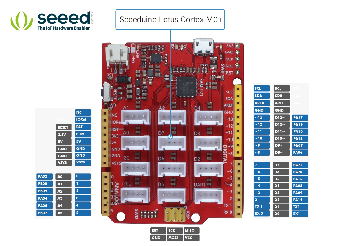
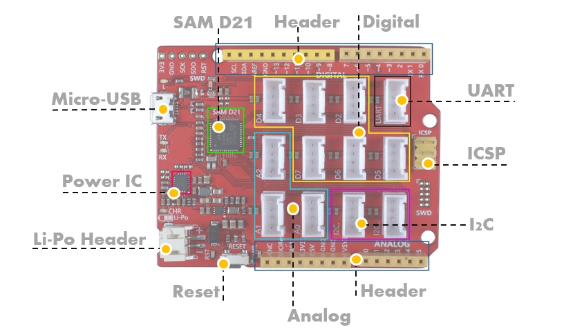
Hardware Overview
The images below show an overview of Seeeduino Lotus hardware features. The pin-out and alternate functions of various pins of Seeeduino Lotus are shown in the pin-out diagram. This could be used as a quick reference.
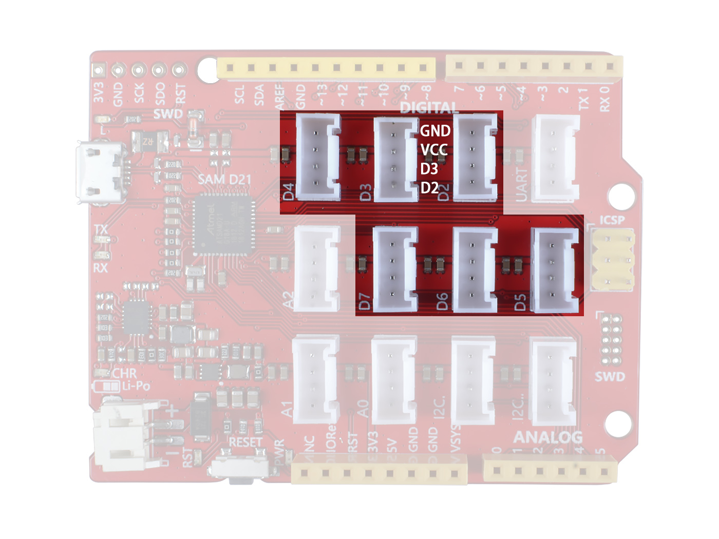
- Grove Digital
There are 6 grove digital connectors, let's take D3 for instance:
GND: System GND
VCC: Output 3.3V VCC
D3: Connect to digital pin 3
D2: Connect to digital pin 2
You can find the silkscreen on the back of the board.
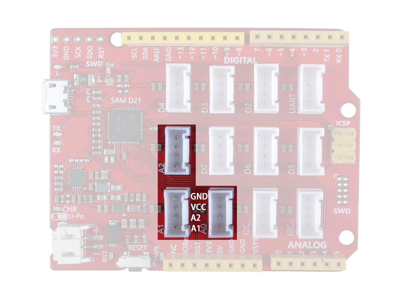
- Grove Analog
There are three analog Grove connectors, the input voltage range from 0~3.3V. If you need more than 3 analog input, you can use the analog pin in the header zone.
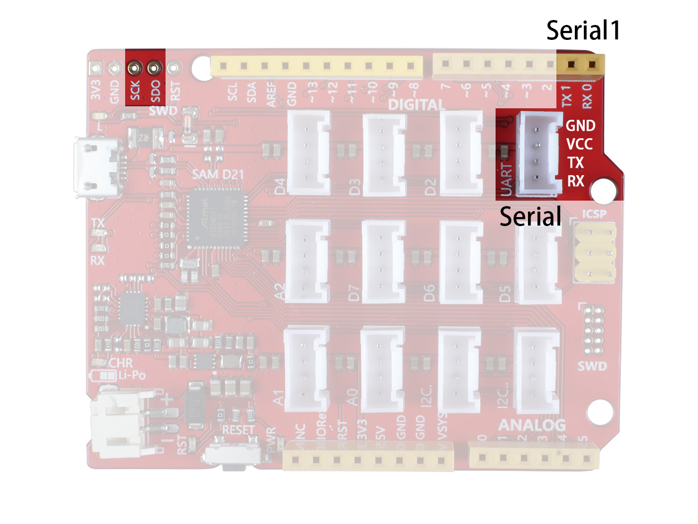
- Grove UART
We provide 3 hardware UART Port, one Grove UART, TX-RX pins in the header, and Multiplexed function pin SCK SDO in the SWD port. However the Multiplexed pin is not supported by the firmware now. So actually, only two hardware UART are available now. Serial corresponds to Grove UART, and Serial1 corresponds to RX-TX in the header zone.
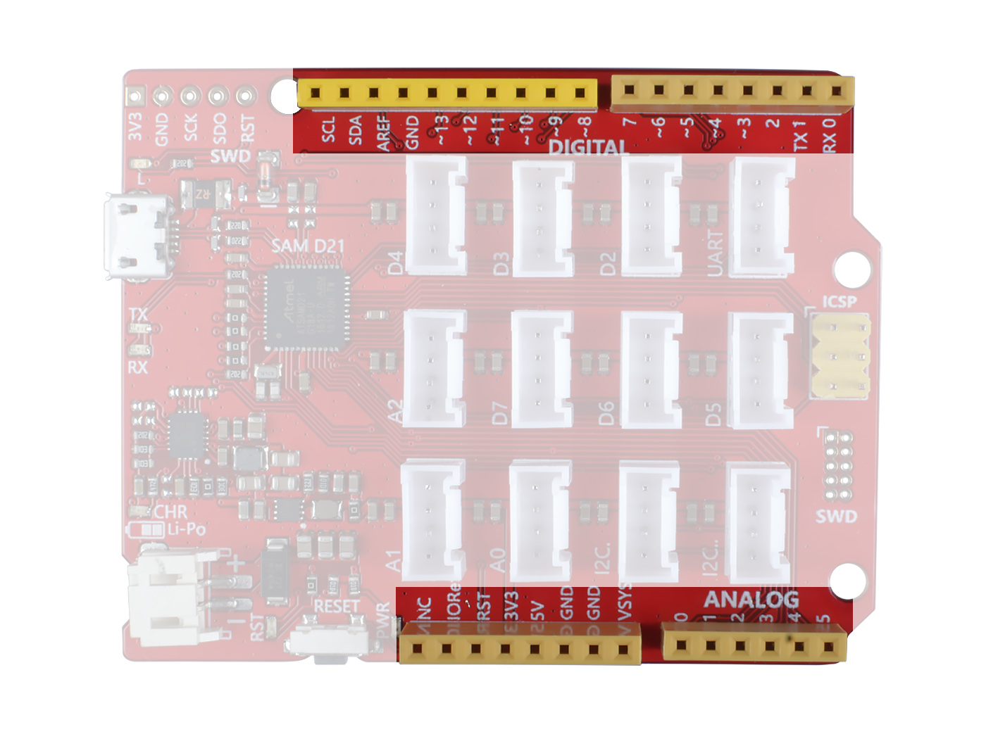
- Female Header
The Seeeduino Lotus Cortex-M0+ female header is fully compatible with Arduino UNO. It is worth mentioning that, in the DIGITAL part, all pins with a ~ in front support PWM output. Which means D3,D4,D5,D6,D8,D9,D10,D11,D12,D13, ten in total.
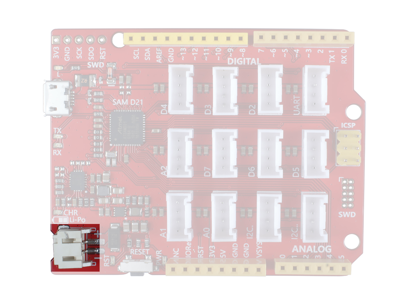
- Li-Po Header
You can use both USB and Li-Po battery supply for Seeeduino Lotus Cortex-M0+. Also, you can use this board to charge your Li-Po battery. When you power the board with USB and plug the Li-Po battery at the same time, the Li-Po battery will be charged, and the CHR LED will flash. After the battery is fully charged, the CHR LED will stop flashing.
Getting Started
Hardware
First of all, you need to:
-
Get a Micro-USB cable You need a Micro-USB cable first; the data cable of an Android Phone will do fine. If you can't find one, you can buy one here.
-
Connect the board Connect the Arduino board to your computer using the USB cable. The green power LED (labelled PWR) should go on.
Software
- Step 1. You need to Install an Arduino Software.

Launch the Arduino application
Double-click the Arduino application (arduino.exe) you have previously downloaded.
If the Arduino Software loads in a different language, you can change it in the preferences dialog. See the Arduino Software (IDE) page for details.
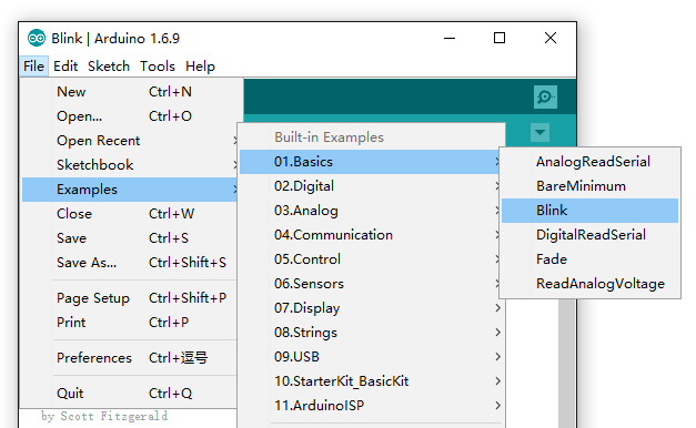
- Step 2. Open the Blink example
Open the LED blink example sketch: File > Examples >01.Basics > Blink.
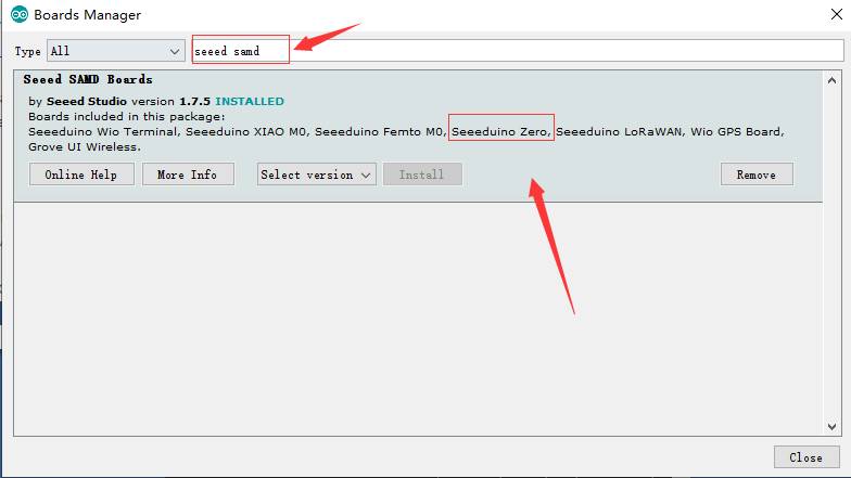
- Step 3. Add the Seeed Board
Please follow the Seeed Board Intallation Guide to add the Seeeduino samd into your Arduino IDE.
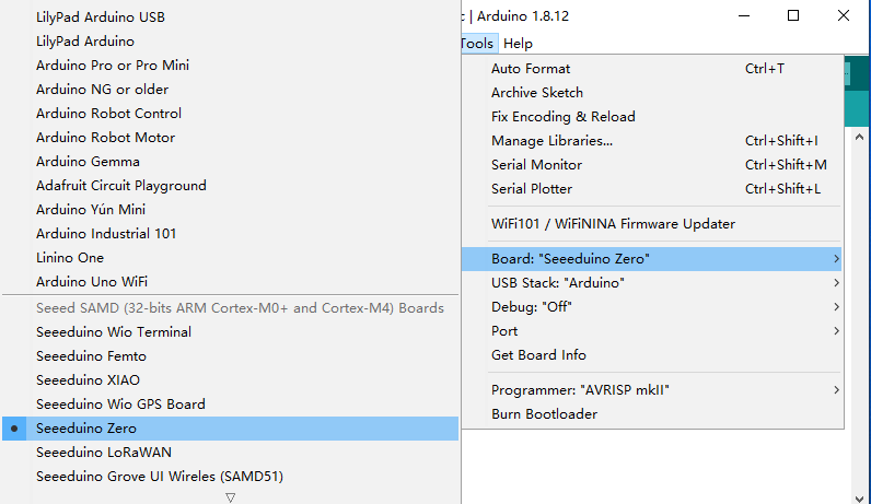
- Step 4. Select your board and port
You'll need to select the entry in the Tools > Board menu that corresponds to your Arduino. Selecting a Seeeduino Zero.
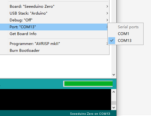
Select the serial device of the Arduino board from the Tools | Serial Port menu. This is likely to be COM3 or higher (COM1 and COM2 are usually reserved for hardware serial ports). To find out, you can disconnect your Arduino board and re-open the menu; the entry that disappears should be the Arduino board. Reconnect the board and select that serial port.
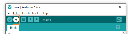
- Step 5.Upload the program
Now, simply click the "Upload" button in the environment. Wait a few seconds and if the upload is successful, the message "Done uploading." will appear in the status bar.
A few seconds after the upload finishes, you should see the pin 13 (L) LED on the board start to blink (in orange). If it does, congratulations! You've gotten Arduino up-and-running. If you have problems, please see the troubleshooting suggestions.
Schematic Online Viewer
Resources
Tech Support & Product Discussion
Thank you for choosing our products! We are here to provide you with different support to ensure that your experience with our products is as smooth as possible. We offer several communication channels to cater to different preferences and needs.