Get Started with Wio Terminal
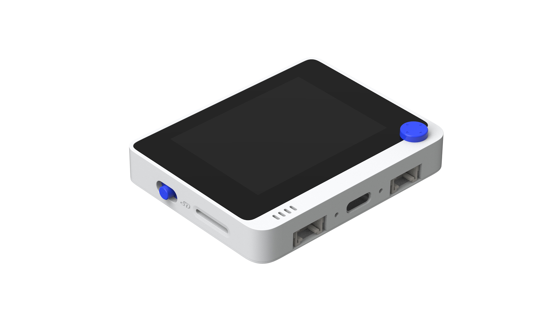
The Wio Terminal is a SAMD51-based microcontroller with Wireless Connectivity powered by Realtek RTL8720DN that’s compatible with Arduino and MicroPython. Currently, wireless connectivity is only supported by Arduino. It runs at 120MHz (Boost up to 200MHz), 4MB External Flash and 192KB RAM. It supports both Bluetooth and Wi-Fi providing backbone for IoT projects. The Wio Terminal itself is equipped with a 2.4” LCD Screen, onboard IMU(LIS3DHTR), Microphone, Buzzer, microSD card slot, Light sensor, and Infrared Emitter(IR 940nm). On top of that, it also has two multifunctional Grove ports for Grove Ecosystem and 40 Raspberry pi compatible pin GPIO for more add-ons.

Feature
- Highly Integrated Design
- MCU, LCD, WIFI, BT, IMU, Microphone, Speaker, microSD Card, Light Sensor, 5-Way Switch, Infrared Emitter (IR 940nm), Crypto-authentication Ready
- Powered by Microchip ATSAMD51P19
- ARM Cortex-M4F core running at 120MHz(Boost up to 200MHz)
- 4 MB External Flash, 192 KB RAM
- Comprehensive Protocol Support
- SPI, I2C, I2S, ADC, DAC, PWM, UART(Serial)
- Powerful Wireless Connectivity (supported only by Arduino)
- Powered by Realtek RTL8720DN
- Dual Band 2.4Ghz / 5Ghz Wi-Fi (802.11 a/b/g/n)
- BLE / BLE 5.0
- USB OTG Support
- USB Host
- USB Client
- Grove Ecosystem
- Software Support
- Arduino
- MicroPython
- ArduPy
- AT Firmware
Specification
Hardware Overview

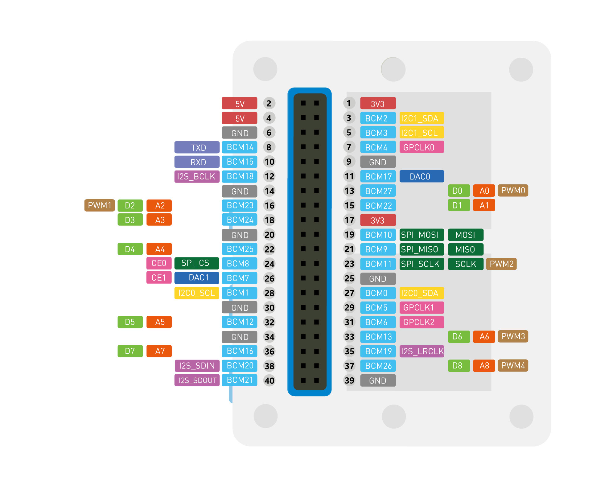
Pinout Diagram

Getting Started
Hardware
Materials required
- Wio Terminal x 1
- Computer x 1
- USB Type-C Cable x 1
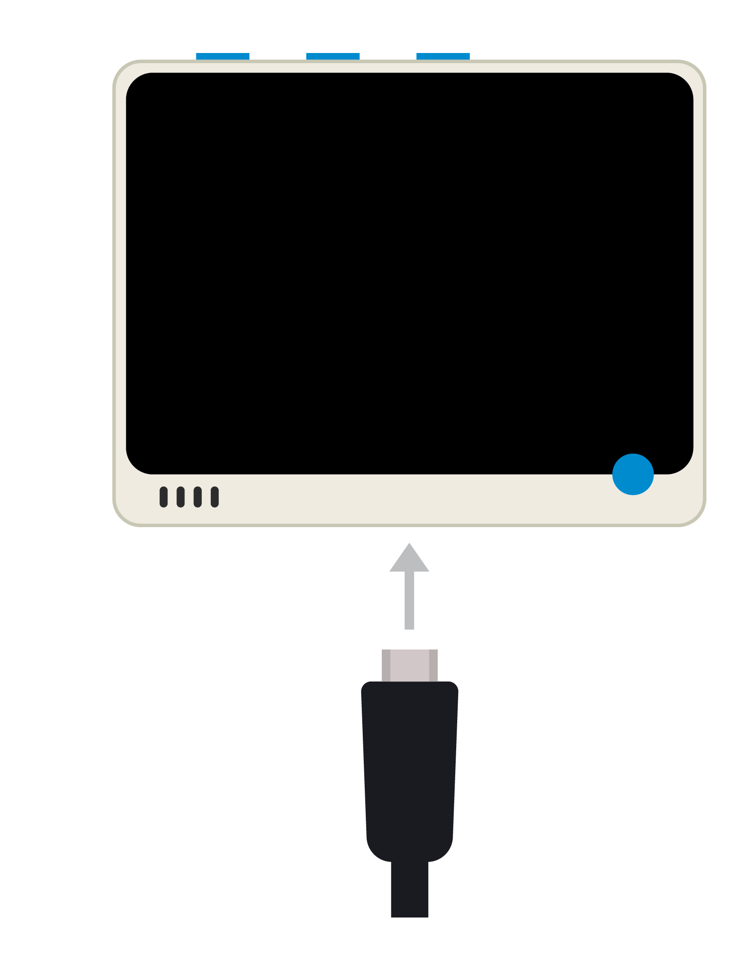
Connect the Wio Terminal to your computer via USB cable. The blue LED on the back should light up.
Software
- Step 1. You need to Install an Arduino Software.

Launch the Arduino application
Double-click the Arduino IDE application you have previously downloaded.
If the Arduino Software loads in a different language, you can change it in the preferences dialog. See the Arduino Software (IDE) page for details.
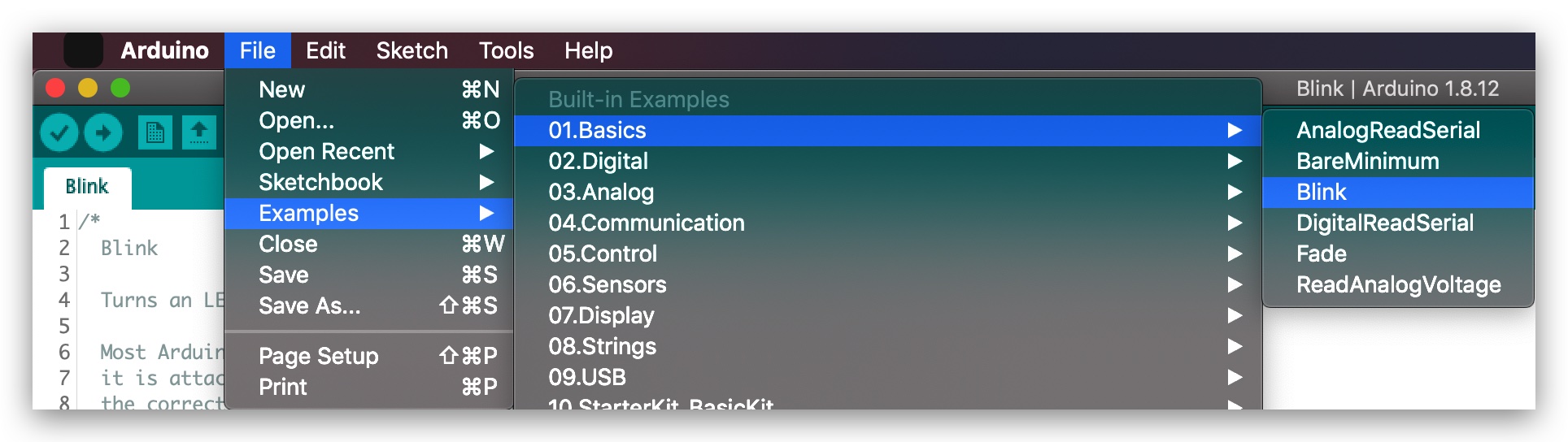
- Step 2. Open the Blink example
Open the LED blink example sketch: File > Examples >01.Basics > Blink.
- Step 3. Add the Wio Terminal Board Library
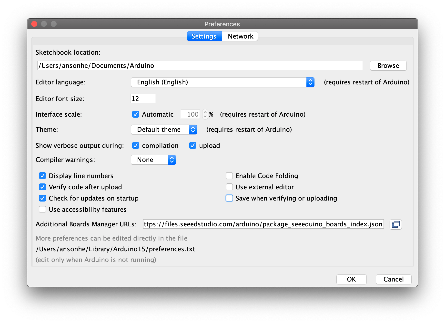
1.Open your Arduino IDE, click on File > Preferences, and copy below url to Additional Boards Manager URLs:
https://files.seeedstudio.com/arduino/package_seeeduino_boards_index.json
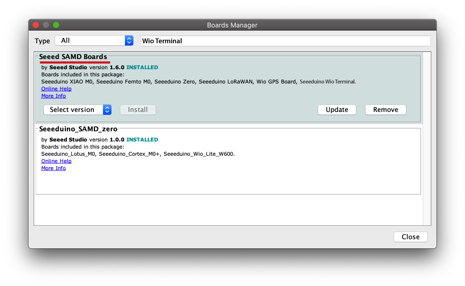
2.Click on Tools > Board > Board Manager and Search Wio Terminal in the Boards Manager.
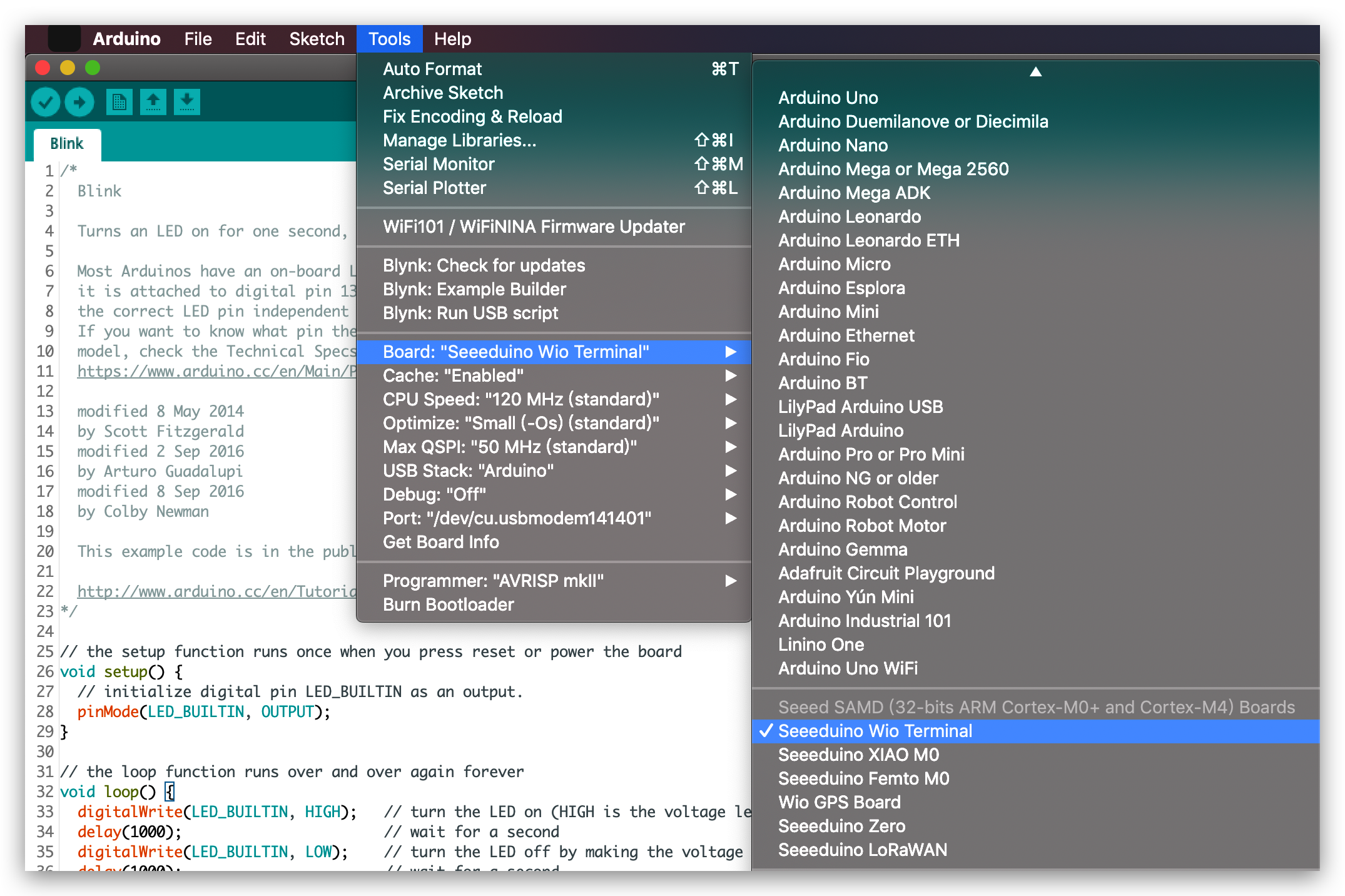
- Step 4. Select your board and port
You'll need to select the entry in the Tools > Board menu that corresponds to your Arduino. Selecting the Wio Terminal.
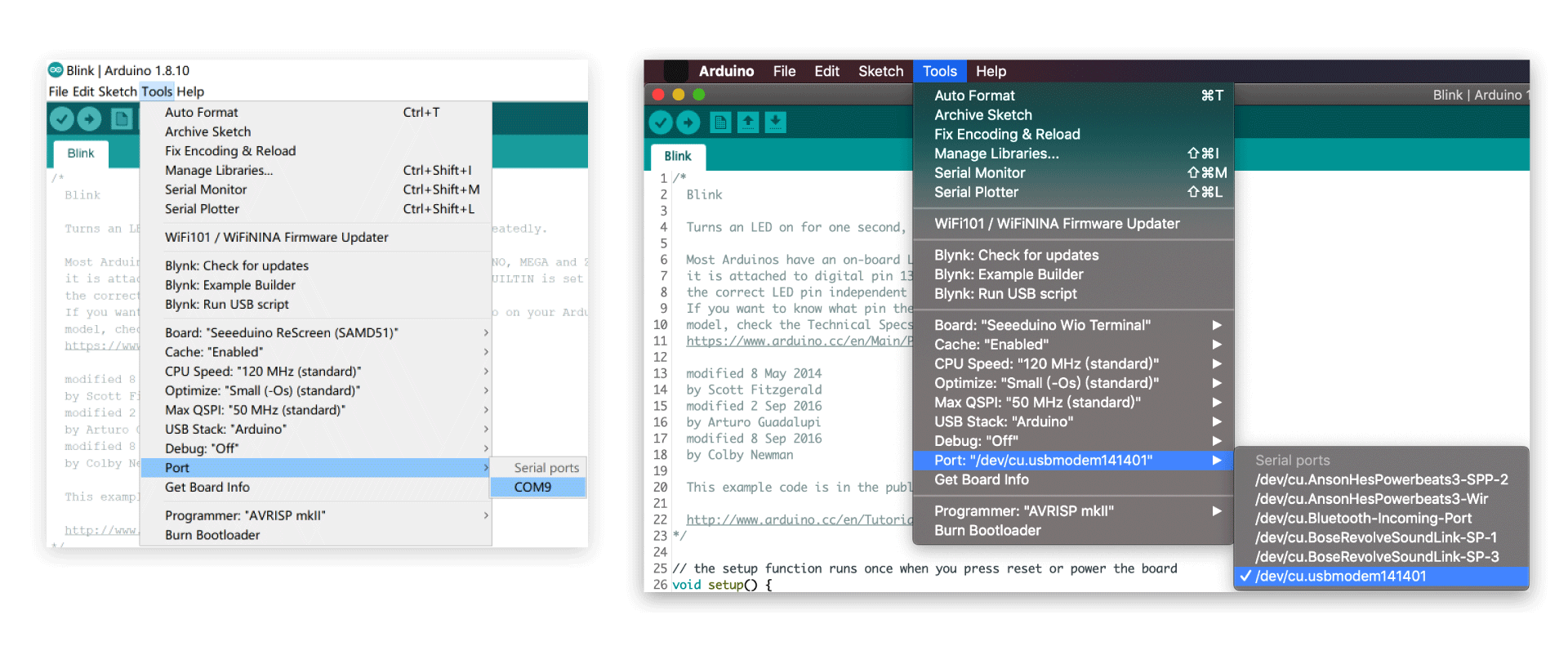
Select the serial device of the Wio Terminal board from the Tools -> Port menu. This is likely to be COM3 or higher (COM1 and COM2 are usually reserved for hardware serial ports). To find out, you can disconnect your Wio Terminal board and re-open the menu; the entry that disappears should be the Arduino board. Reconnect the board and select that serial port.
For Mac User, it will be something like /dev/cu.usbmodem141401
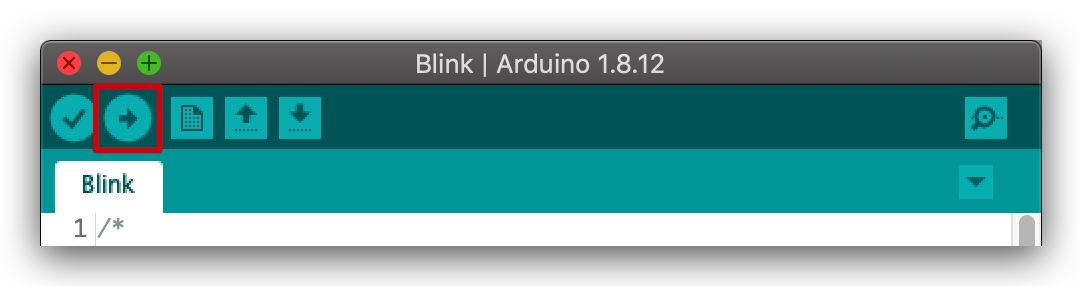
- Step 5. Upload the program
Now, simply click the Upload button in the environment. Wait a few seconds and if the upload is successful, the message "Done uploading." will appear in the status bar.
A few seconds after the upload finishes, you should see the LED at the bottom of the Wio Terminal start to blink. If it does, congratulations! You've gotten Wio Terminal up-and-running. If you have problems, please see the FAQ suggestions.
If you are not able to upload the sketch, mostly it's because Arduino IDE was not able to put Wio Terminal to bootloader mode. (Because MCU was halted or your program handling USB,) Workaround is putting your Wio Terminal to bootloader mode manually, as shown in FAQ.
Please feel free to go though other tutorials of Wio Terminal and start building your IoT projects!
FAQ
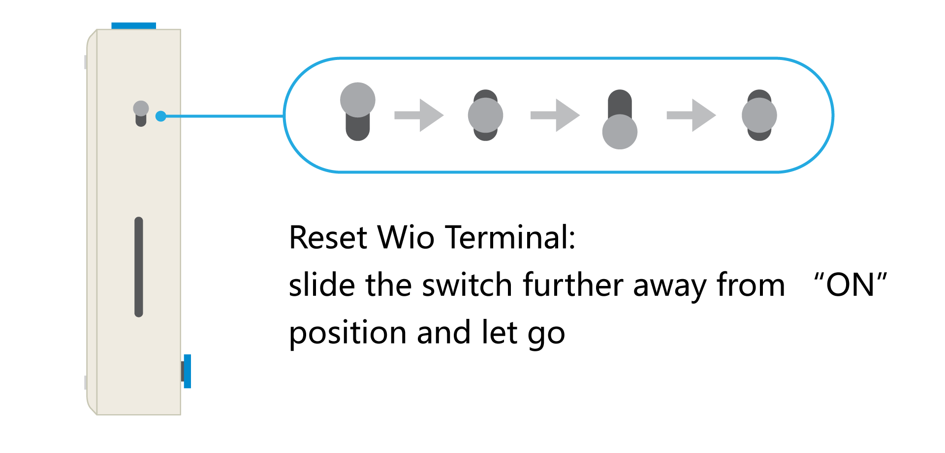
Reset Wio Terminal:
Enter Bootloader:
This is very useful when Wio Terminal crashes or somehow USB serial is not showing up in Arduino IDE. Slide the switch twice very quickly, as followed:
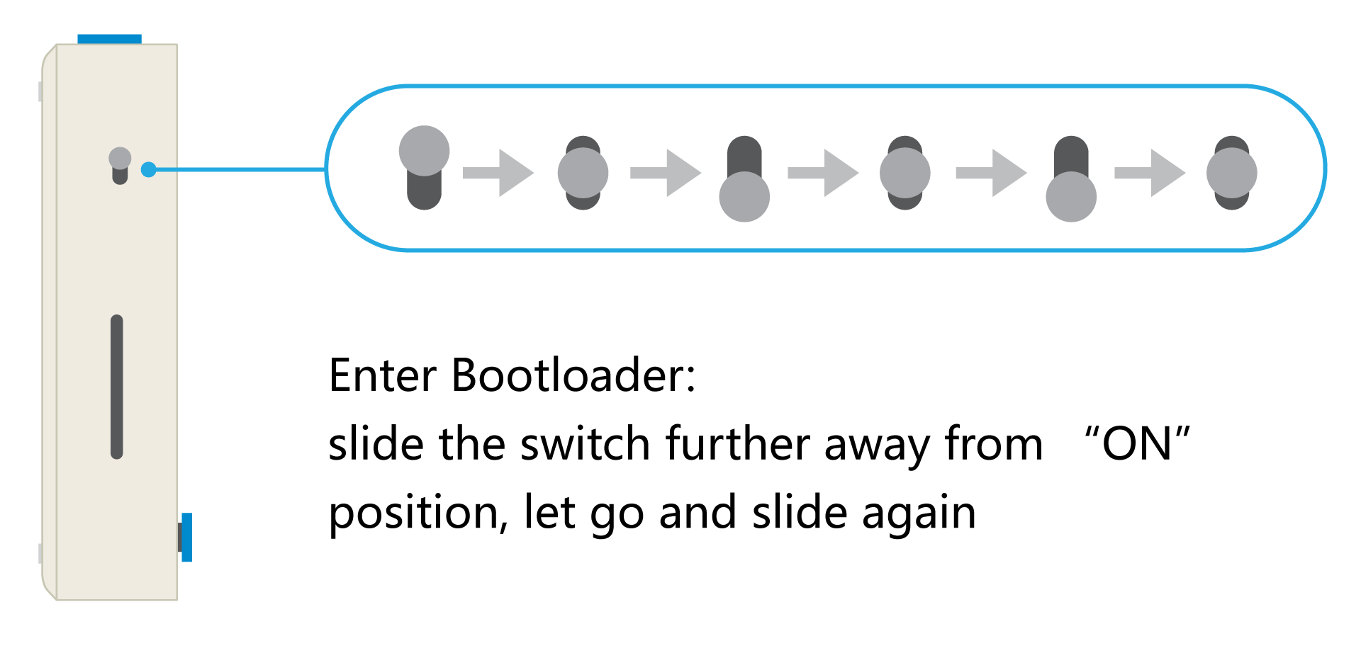
Once Wio Terminal is in the Bootloader mode, the blue LED will start to breath in a way that is different to blinking. Check the port again and it should appeared.
Test with SWD
There are two ways to use SWD to test and debug with Wio Terminal:
From the back of the PCB testing ports.
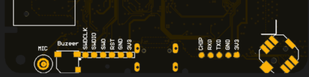
On the left is the testing ports for ATSAMD51:
- SWCLK
- SWDIO
- SWO
- RST
- GND
- 3V3
On the right is the testing ports for RTL8720DN:
- CHIP
- RXD
- TXD
- GND
- 3V3
If you have very frequent debugging needs, you can add SWD debugging to one of the Grove interfaces in the following ways:
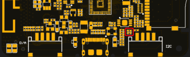
The picture shows the two unmounted resistor positions. You can connect these two pads by soldering a 0 ohm resistor or shorting it. This will connect the SWD interface (SWDIO / SWCLK) of ATSMAD51 to Grove in parallel on the interface.
After our test, the SWD interface is connected in parallel in this way. When powering on and resetting, you need to make sure that the Grove interface is not connected to any Grove module (the module may have pull-up / pull-down resistors, which will affect it), otherwise it will Enter SWD mode directly and cannot run in normal mode (that is, SWDCLK cannot be pulled low during power-on or reset)
In addition to power-on and reset, when using SWD, Digital, Analog, Serial, I2C, there will be no interference, you can switch at any time, but in order to avoid possible problems, we still recommend removing this after completing the program debugging Connection of two pads.
Library File Name Conflicts
After you install seeed-arduinocore-samd, the core will download some library files to drive different devices at the same time, such as TFT_eSPI.h, etc. When you upload the program, an error will occur and the compiler will prompt you that multiple library files are found. E.g:
Multiple libraries were found for "TFT_eSPI.h"

Used: C:\Users\Dave\Documents\Arduino\libraries\TFT_eSPI-master

Not used: C:\Users\Dave\AppData\Local\Arduino15\packages\Seeeduino\hardware\samd\1.8.2\libraries\Seeed_Arduino_LCD
If you use a seeed-SAMD device, please select and use the library file in the seeed folder and move the conflicting library file out of the arduino library.
When you use other devices, please remove the library files in the seeed folder and keep the compiler calling only one library file. This can solve the incompatibility problem caused by different versions of library files with the same name.

You may refer to the specific library lists here: https://github.com/Seeed-Studio/ArduinoCore-samd/tree/master/libraries
Wio Terminal Classroom
Lesson 1 - Hello World
Lesson 2 - Drawing Shapes
Lesson 3 - Displaying Fonts
Lesson 4 - Displaying Images and Simple UI
Lesson 5 - Line Charts and Histograms
Lesson 6 - Using Grove Modules
Lesson 7 - Communication Protocols
Lesson 8 - Built-In Hardware/Sensors Part 1 | 3 Buttons & 5-Way Switch
Lesson 9 - Built-In Hardware/ Sensors Part 2 | Microphone & Buzzer
Lesson 10 - Built-In Hardware/ Sensors Part 3 | Accelerometer & Light Sensor
Lesson 11 - Build a TV Remote using the built-in IR Emitter
Lesson 12 - Smart Garden Project using Wio Terminal
Lesson 13 - Use Wio Terminal as a Mouse for PC
Lesson 14 - Use Wio Terminal as a Keyboard for PC
Wio Terminal in Deep Learning supproted by CAVEDU Education
[Chinese] Here is a series of videos on how do you apply deep learning in Wio Terminal.

Resources
- [PDF] ATSAMD51N19A Datasheet
- [PDF] Wio Terminal Schematics
- [ZIP] Wio Terminal Schematics
- [PDF] Wio Terminal Enclosure Dimensions - Front
- [PDF] Wio Terminal Enclosure Dimensions - Back
- [AI] Wio-Terminal-Screen-Sticker-Design-File(Wio-Terminal-ちゃん)
- [AI] Wio-Terminal-chan-Desgin-File-blue&white
- [DXF] Wio Terminal Enclosure Dimensions - Front
- [DXF] Wio Terminal Enclosure Dimensions - Back
- [DXF] Wio Terminal Battery Chassis Dimensions
- [DXF] Wio Terminal PCB Dimensions
Open Source hardware
This product is fully open-sourced. Access the related open-source documents through this link.
Tech Support & Product Discussion
Thank you for choosing our products! We are here to provide you with different support to ensure that your experience with our products is as smooth as possible. We offer several communication channels to cater to different preferences and needs.