Seeeduino v3.0

Overview
The Seeeduino v3 is a microcontroller board based on the ATmega328, and it's an Arduino compatible board. It has a FTDI USB-to-serial driver chip which can be regarded as a bridge, let your computer can communicate with the board. It has 14 digit pins (which include 6 PWM pins and UART port) and 8 analog pins, a 16 MHz ceramic resonator, a USB connection, a reset button, an ICSP header and a DC power jack. It has two toggle switches, one for input voltage change of ATmega328, the other is enable/disable pin of DTR, which you can use FTDI function alone without the influence of ATmega328. It also has two white Grove connectors, and make it convenient for using Grove products with the board.
Specifications
| Item | Value |
|---|---|
| Microcontroller | Atmel ATmega328 (AVR 8-bit) in TQFP-32 package |
| Board (Boot-loader) | Arduino Duemilanove w/Atmega328 |
| Operating Voltage | 5V or 3.3V (choice by slide switch) |
| Maximum output current of 3V3 port and 5V port | 5V port - 500mA, 3V3 port - 800mA(need to be powered by DC jack or Vin) |
| Maximum output current of digit pins | 40mA |
| miniUSB Input Voltage | 5V. Maximum is 5.5V. |
| DC Jack & Vin Input Voltage | 7V to 12V (lower is preferred). Maximum is 20V. If input lower than 7V and switch set to 5V, then VCC at AVR is about 2V below the input. |
| Digital I/O Pins | 14 (of which 6 provide PWM output) |
| Analog Input Pins | 8 (of which 2 are used for I2C communication - PC4 and PC5) |
| Flash Memory | 32 KB |
| SRAM | 2 KB |
| EEPROM | 1 KB |
| Clock Speed | 16 MHz |
Usage
USB-to-Serial
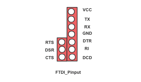
The Seeeduino has a FTDI USB-to-serial driver chip onboard - FT232R which programmed as a USB-to-serial converter.

Ten pins of FT232R have been pointed out, it beside the ICSP port, make it convenient for you to use those pins if needed.
There's a toggle switch "M_RST_AUTO" onboard. This determines whether the DTR signal from the host is allowed to reset the ATmega328 micro controller.
Set to "AUTO" for Automatic mode, which allows the host to reset the microcontroller using the DTR signal to automatically reset the microcontroller. Note: This position is required during development, thus it will be the default position for most people.
Set to "M" for Manual mode, which disables the DTR signal from the host, thus requiring the user to physically press the RESET button to reset the micro controller. Also, it is necessary to set it to "M" mode if you wanna use FT232R alone.
More information about FTDI chip, you can refer to the homepage of FTDI
Breakout
The Seeeduino is a main board based on ATmega328, and all useful pins are pointed out. There are power pins, 14 digital IO pins and 8 analog pins on Seeeduino, meantime, six of the digital IO pins can be used as PWM outputs. All the pins of Seeeduino are wired to 2.54mm spaced headers.

Each of the 14 digital pins on the board can be used as an input or output, using pinMode()digitalWrite()digitalRead() functions. They operate at 5 volts or 3.3 volts while turning the toggle switch "3V3_VCC_5V" to two different positions. And each pin can provide or receive a maximum of 40 mA. And a SoftwareSerial library allows for serial communication on any of digital pins.
UART: D0 (RX) and D1 (TX).
It can be used to receive and transmit TTL serial data. These two pins have been connected to FTDI chip, which makes a direct communication between your computer and peripheral devices.
External Interrupts: D2 and D3.
The two pins are the external interrupts from ATmega328, it can be configured to trigger an interrupt on a low value, a rising or falling edge, or a change in value. More information refer to attachInterrupt() function.
PWM: D3, D5, D6, D9, D10, D11.
Pulse Width Modulation, is a technique for getting analog results with digital means. It can be generated by using analogWrite(), with an output of a series of repeated HIGH and LOW pulse signals. The PWM frequency of Seeeduino is about 500Hz, and Provide 8-bit PWM output with the analogWrite() function. More information please refer to PWM
SPI: D10 (SS), D11 (MOSI), D12 (MISO), D13 (SCK).
These pins support SPI communication using the SPI library.
SPI diagram
| MISO (D12) | VCC |
|---|---|
| SCK(D13) | MOSI(D11) |
| Reset | GND |
"L" indicator.
There's a led "L" on the board, and it is connected to D13, you can control this led via D13.
There are eight analog pins on the analog header, labeled A0 through A7. Each pin can provide 10 bits of resolution. This means that an analog input between 0V and 5V (0V to 3.3V) can be mapped to 0 to 1024 (0 to 675). You can use analogRead() to get the value from an analog input.
I2C: A4 (SDA) & A5 (SCL).
Seeeduino can generate a bus clock to control its slave I2C device with a specific address. Grove I2C also connects to A4 & A5.
There's a reset button on the board, which connected to the pin of RST. Press the button and this pin will be pulled down, then the ATmega328 will restart.
Power
The Seeeduino can be powered through USB or DC Jack connector (Vin). If you use USB to power it, the input voltage should be regulated 5VDC, like a computer or a USB wall adaptor. On the other hand, when you choose DC Jack, which should be a 2.1mm center-positive plug with 5.5mm outer hole. DC power input should be 7-20V, however, as a result of overheat from a higher input voltage, 7-12V is recommended.There's a voltage regulator on the board, so it can convert 5v to 3.3v. While turning the toggle switch "3V3_VCC_5V" to 3V3 position, the input voltage of ATmega328 will be changed to 3.3v, meantime, the board will operate 3.3 volts.
Grove connectors
The Seeeduino has two white Grove connectors, one is IIC port and the other is UART port. This two port are pointed out from ATmega328, it is designed for plugging Grove products onto the board more conveniently.
On-board Indicators
There are some indicators on the board, which can display some status.
| Label | Connection |
|---|---|
| User LED with "L" label | It is connected to ATmega328P PB5/SCK pin (Digital header pin 13). |
| Reset LED with "RST" label | It is connected to ATmega328P PC6/RESET pin. It is lite when Reset is low. |
| Power LED with "PWR" label | It is connected to ATmega328P VCC pin. |
| Transmit LED with "TX" label | It is connected to FT232RL CBUS1 pin. |
| Receive LED with "RX" label | It is connected to FT232RL CBUS0 pin. |
Related Reading
Licensing
This documentation is licensed under the Creative Commons Attribution-ShareAlike License 3.0 Source code and libraries are licensed under GPL/LGPL, see source code files for details.
Schematic Online Viewer
Resources
- [Source]Seeeduino v3.0_Source_files
- [PDF]Seeeduino v3.0 PCB
- [PDF]Seeeduino v3.0 SCH
- [PDF]Schematic in pdf
Tech Support & Product Discussion
Thank you for choosing our products! We are here to provide you with different support to ensure that your experience with our products is as smooth as possible. We offer several communication channels to cater to different preferences and needs.