Getting Started with Seeed Studio XIAO SAMD21 Series
| Seeed Studio XIAO SAMD21 | Seeed Studio XIAO SAMD21 Plus |
|---|---|
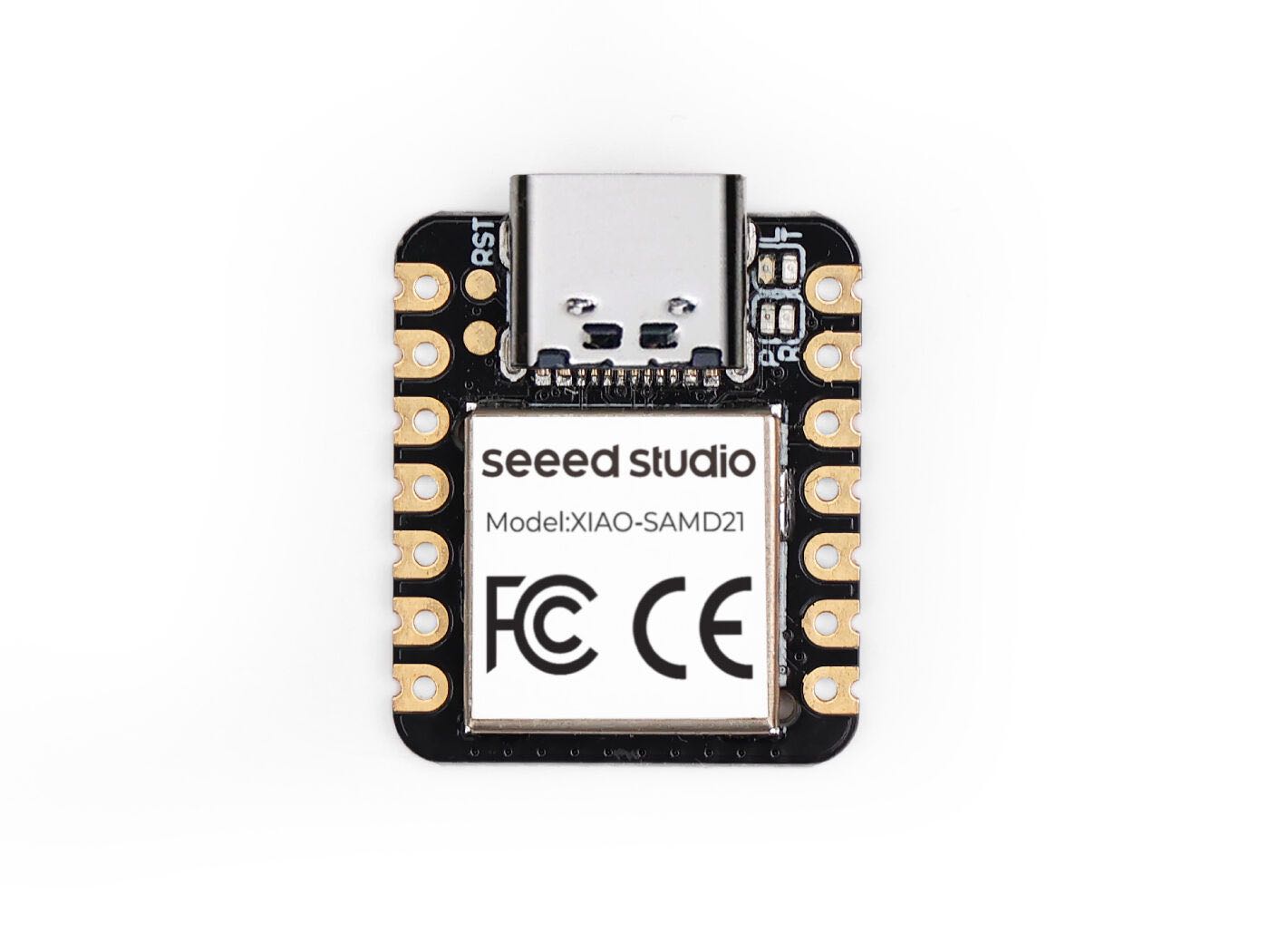 | 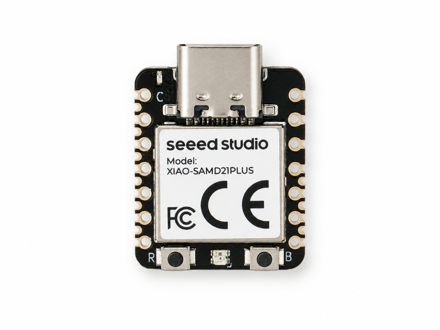 |
Overview
The Seeed Studio XIAO SAMD21, which used to be named Seeeduino XIAO, is the first debut of the Seeed Studio XIAO family, a series of powerful thumb-size dev boards compatible with Arduino. It carries the powerful ATSAMD21G18A-MU which is a low-power microcontroller. On the other hand, this little board has good performance in processing but needs less power. It is designed in a tiny size and can be used for wearable devices and small projects.
Seeed Studio XIAO SAMD21 has 14 PINs, which can be used for 11 digital interfaces, 11 analog interfaces, 10 PWM interfaces (d1-d10), 1 DAC output pin D0, 1 SWD pad interface, 1 I2C interface, 1 SPI interface, 1 UART interface, Serial communication indicator (T/R), Blink light (L) through pin multiplexing. The colors of LEDs(Power, L,RX,TX) are green, yellow, blue, and blue. Moreover, Seeed Studio XIAO SAMD21 has a Type-C interface that can supply power and download code. There are two reset buttons, you can short-connect them to reset the board.
Powered by Microchip's SAMD21G18A ARM Cortex-M0+ 32-bit processor, XIAO SAMD21 Plus brings enhanced flexibility and expandability to the tiny and versatile XIAO SAMD21. While maintaining all the powerful features including Arduino, MicroPython, and PlatformIO compatibility, the Plus variant features redesigned castellations and backside pad layout, offering 16 additional GPIOs, integrated Li-ion battery management, dedicated Reset and Boot buttons, and an onboard programmable WS2812 RGB LED. It is ideal for advanced IoT projects, battery-powered wearables, embedded applications, and production-ready SoM designs.
Documentations
There are two documents on the usage of Seeed Studio XIAO SAMD21 which focus on different areas, check the table below for reference:
| Documentation by Seeed | Documentation by Nanase |
|---|---|
| Pinout Digram | Interface |
| Seeed Studio XIAO SAMD21 Getting Started | Seeed Studio XIAO SAMD21 with MicroSD Card(SPI) |
| Seeed Studio XIAO SAMD21 GPIO Usage | Seeed Studio XIAO SAMD21 with GPS(UART) |
| Seeed Studio XIAO SAMD21 Resources | Single Cycle IOBUS |
Features
- Powerful MCU: Microchip ATSAMD21G18A Arm® Cortex®-M0+ processor at 48 MHz, with 256 KB Flash, 32 KB SRAM, and native USB support.
- Expanded I/O: XIAO SAMD21 Plus retains the standard 14-pin XIAO layout and adds 16 GPIOs through 1.27 mm backside SMD castellations, with PWM, DAC, I2C, UART, SPI, I2S, and SWD support.
- Integrated Power Management: Supports direct Li-ion battery connection, onboard charging, backflow protection, and charge-status indication.
- Flexible Development: Compatible with Arduino IDE, PlatformIO, CircuitPython, and TinyGo.
- Compact and Ecosystem-Ready: Maintains the 21 × 17.8 mm breadboard-friendly XIAO form factor while adopting the standardized XIAO Plus backside layout for expansion boards and custom carrier designs.
Specification
| Product Name | Seeed Studio XIAO SAMD21 | Seeed Studio XIAO SAMD21 Plus |
|---|---|---|
| Chipset | Microchip SAMD21G18 | |
| Processor | Arm® Cortex®-M0+ processor running at up to 48 MHz | |
| RAM | 32 KB SRAM | |
| Flash | 256 KB Flash | |
| Interface | GPIO Pin ×14 | GPIO Pin ×30 |
| Onboard | User LED ×1 | User LED ×1 |
| Battery Management | None | Onboard PMIC |
| Power | Input Voltage (Type-C): 5 V | Input Voltage (Type-C): 5 V |
| BAT-to-3V3 Backflow Protection | No | Yes |
| Working Temperature | -40°C to 85°C | |
| Dimensions | 21 × 17.8 mm | |
| Software Compatibility | Arduino, PlatformIO, MicroPython, CircuitPython, Zephyr, and more | |
Hardware Overview
- XIAO SAMD21
- XIAO SAMD21 Plus
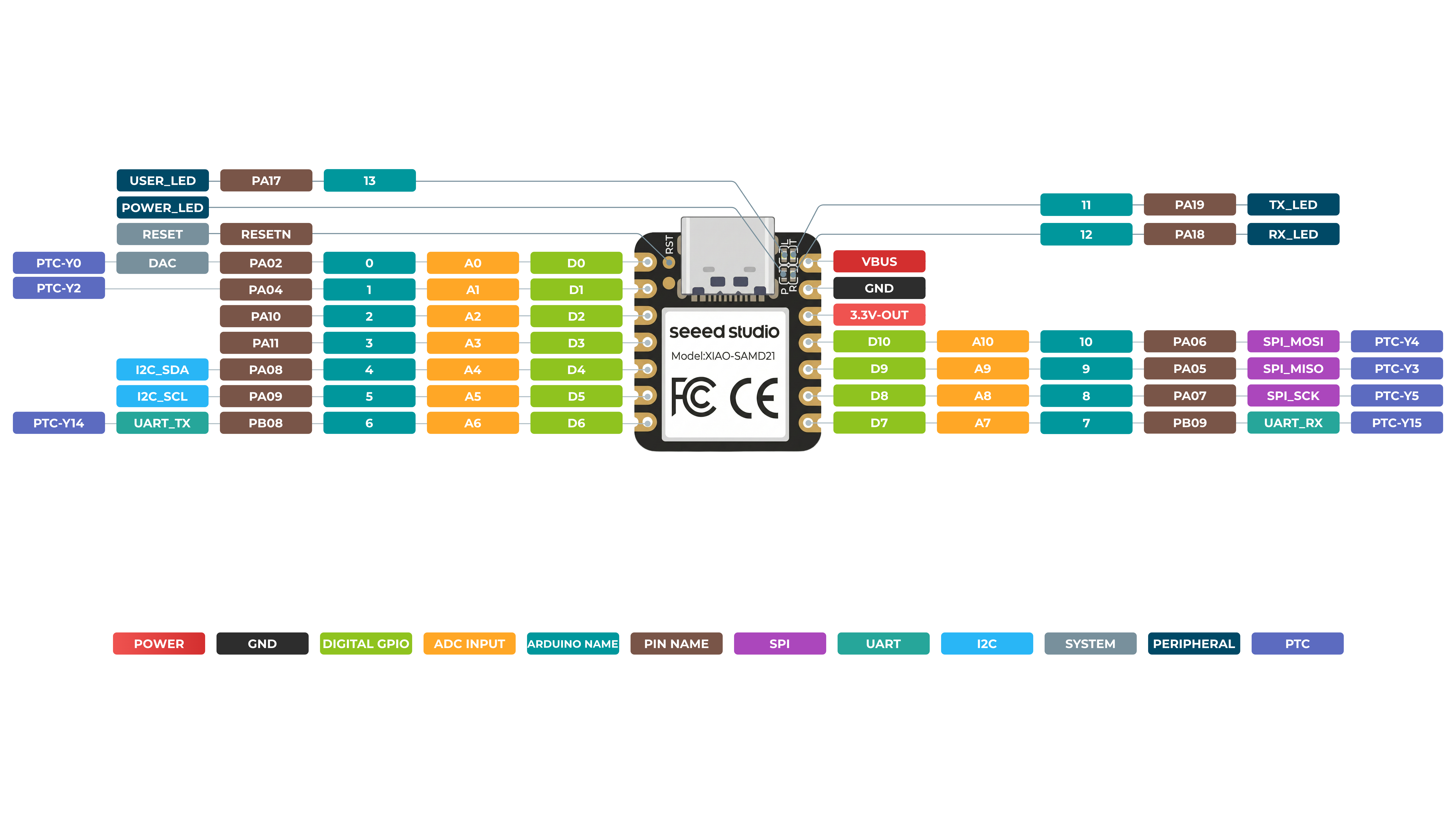
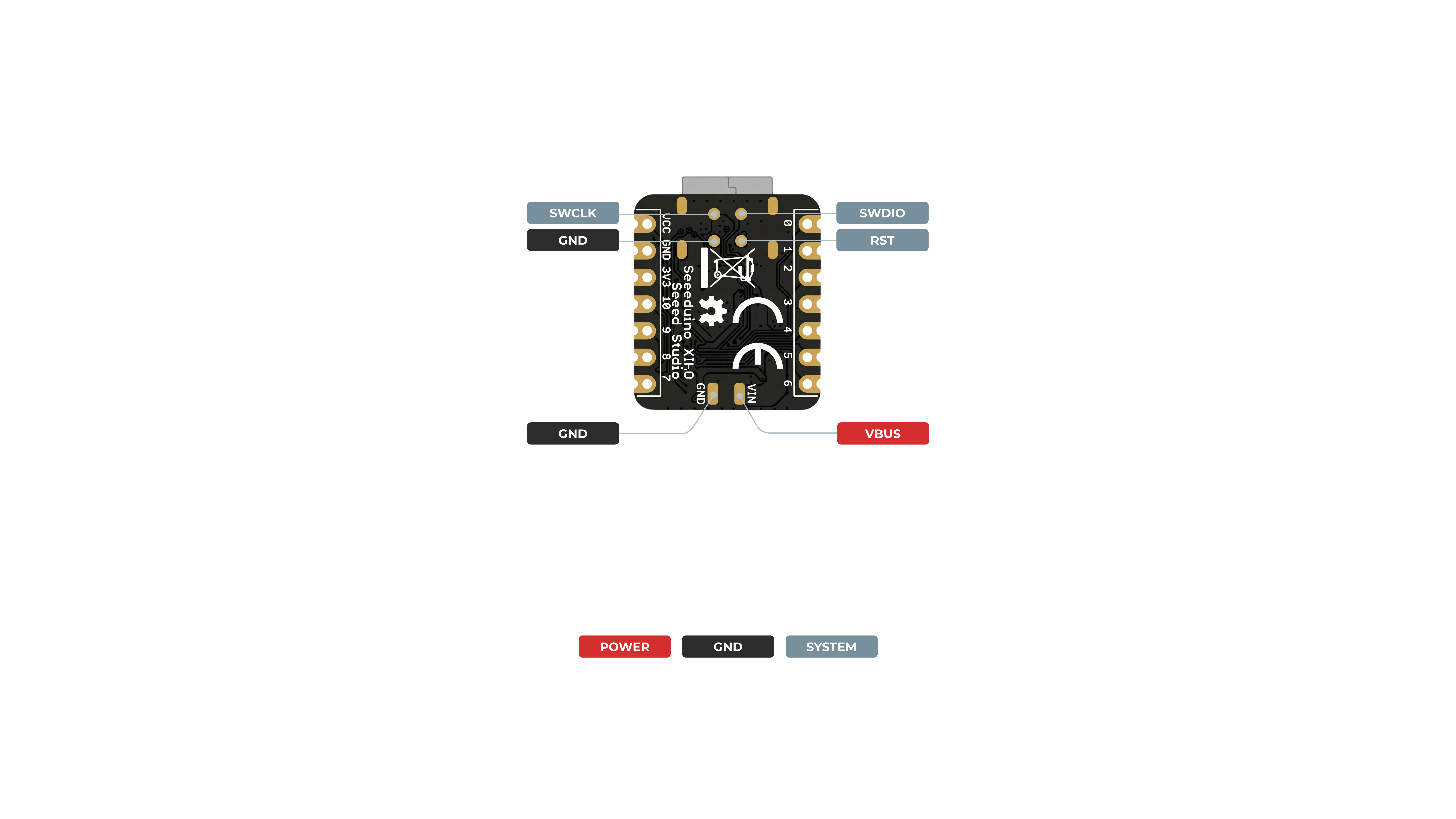
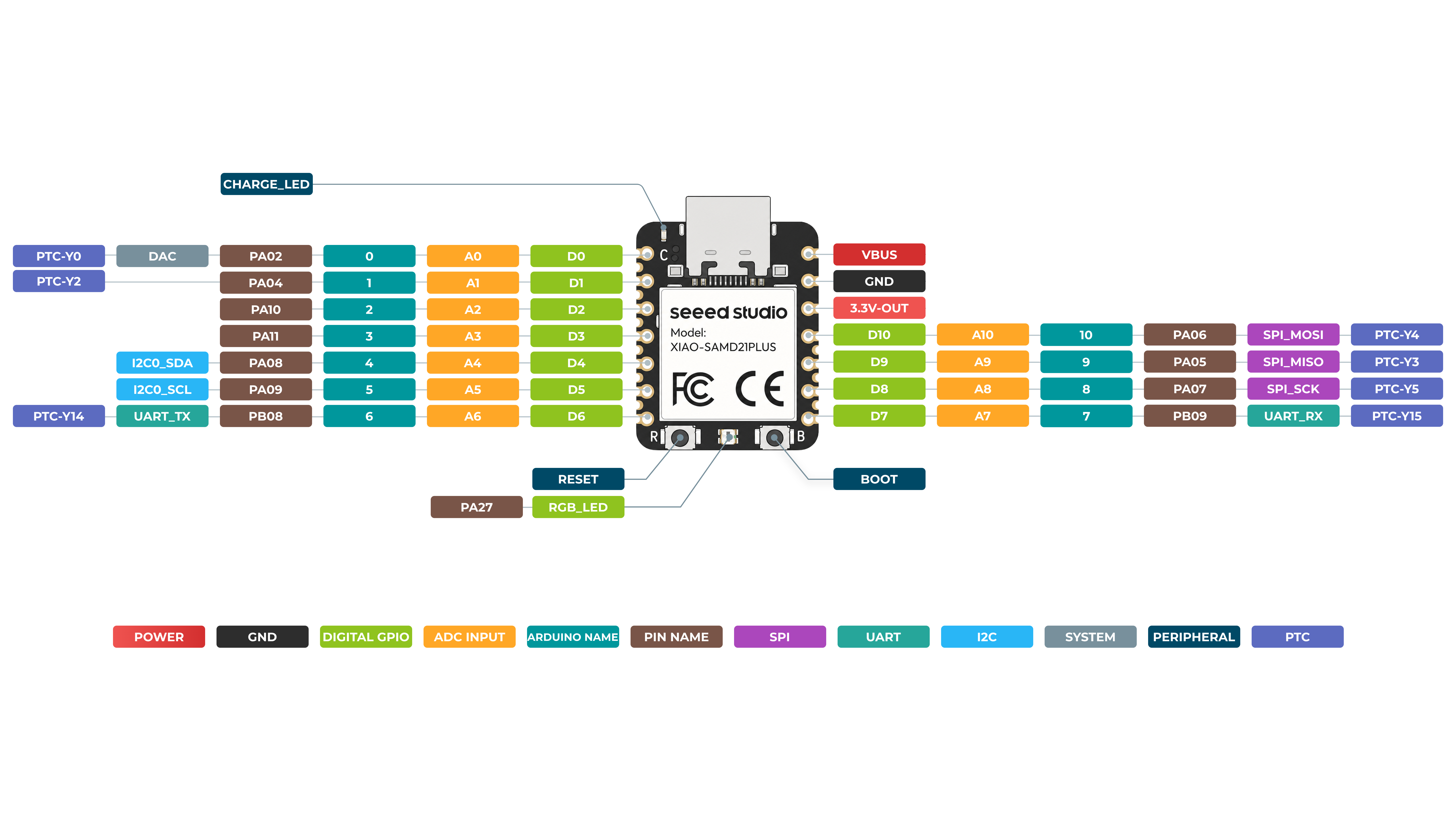
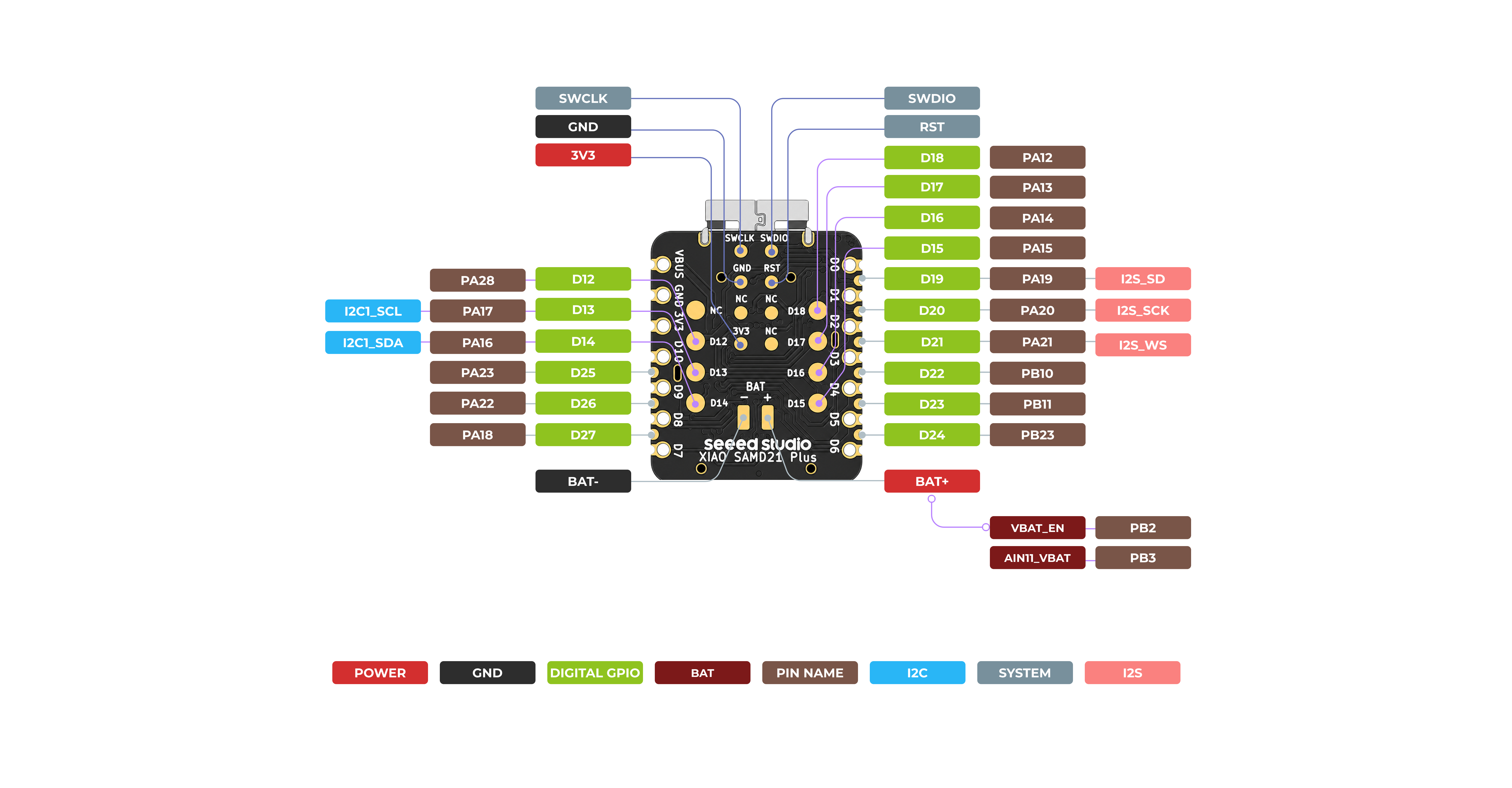
For general I/O pins: Working voltage of MCU is 3.3V. Voltage input connected to general I/O pins may cause chip damage if it' higher than 3.3V .
For power supply pins: The built-in DC-DC converter circuit able to change 5V voltage into 3.3V allows to power the device with a 5V supply via VIN-PIN and 5V-PIN.
It is critical to understand that the VIN and GND pads on the back of the XIAO SAMD21 are not designed for directly connecting a battery, especially not a rechargeable lithium battery (LiPo/Li-Ion). The board lacks the essential battery management circuitry required for safe operation. These pads are simply an alternative power input point that bypasses the board's built-in protection diode. If you wish to power your project with a battery, you must use a dedicated external battery management module that provides charging and protection, and then connect that module's regulated output to the XIAO's 5V pin.
Please pay attention to use, do not lift the shield cover.
Pin Map
| XIAO Pin | Function | XIAO SAMD21 | XIAO SAMD21 Plus | Description |
|---|---|---|---|---|
| 5V | VBUS | VBUS | VBUS | USB 5 V power input/output |
| GND | GND | GND | GND | Ground |
| 3V3 | 3V3_OUT | 3V3_OUT | 3V3_OUT | 3.3 V power output |
| D0 | A0 / DAC | PA02 | PA02 | GPIO, ADC AIN0, DAC output; no hardware PWM |
| D1 | A1 | PA04 | PA04 | GPIO, ADC AIN4 |
| D2 | A2 | PA10 | PA10 | GPIO, ADC AIN18 |
| D3 | A3 | PA11 | PA11 | GPIO, ADC AIN19 |
| D4 | SDA0 | PA08 | PA08 | GPIO, ADC AIN16, I2C data |
| D5 | SCL0 | PA09 | PA09 | GPIO, ADC AIN17, I2C clock |
| D6 | TX | PB08 | PB08 | GPIO, ADC AIN2, UART transmit |
| D7 | RX | PB09 | PB09 | GPIO, ADC AIN3, UART receive |
| D8 | SCK | PA07 | PA07 | GPIO, ADC AIN7, SPI clock |
| D9 | MISO | PA05 | PA05 | GPIO, ADC AIN5, SPI data input |
| D10 | MOSI | PA06 | PA06 | GPIO, ADC AIN6, SPI data output |
| D11 | TX_LED | PA19 | - | Internal TX LED on XIAO SAMD21; not defined on Plus |
| D12 | GPIO | PA18 (RX_LED) | PA28 | Plus expansion GPIO |
| D13 | SCL1 | PA17 (USER_LED) | PA17 | Plus expansion GPIO and I2C1 clock |
| D14 | SDA1 | - | PA16 | Plus expansion GPIO and I2C1 data |
| D15 | GPIO | - | PA15 | Plus expansion GPIO |
| D16 | GPIO | - | PA14 | Plus expansion GPIO |
| D17 | GPIO | - | PA13 | Plus expansion GPIO |
| D18 | GPIO | - | PA12 | Plus expansion GPIO |
| D19 | I2S_SD | - | PA19 | Plus expansion GPIO and I2S data |
| D20 | I2S_SCK | - | PA20 | Plus expansion GPIO and I2S clock |
| D21 | I2S_WS | - | PA21 | Plus expansion GPIO and I2S word select |
| D22 | GPIO | - | PB10 | Plus expansion GPIO |
| D23 | GPIO | - | PB11 | Plus expansion GPIO |
| D24 | GPIO | - | PB23 | Plus expansion GPIO |
| D25 | GPIO | - | PA23 | Plus expansion GPIO |
| D26 | GPIO | - | PB2 | Plus expansion GPIO |
| D27 | GPIO | - | PA18 | Plus expansion GPIO |
| VBAT_EN | Battery Enable | - | PB2 | Battery power control on Plus |
| AIN11_VBAT | Voltage Read | - | PB3 | Read the battery voltage on Plus |
| Reset | RESETN | RESETN | RESETN | Active-low reset input, package pin 40 |
| TX_LED | LED | PA19 | - | Original-board TX indicator, active low |
| RX_LED | LED | PA18 | - | Original-board RX indicator, active low |
| USER_LED | LED | PA17 | - | Original-board user LED, active low |
| POWER_LED | Power indicator | 3V3 | - | Original-board green power LED; not an MCU GPIO |
| RGB_LED | WS2812B data | - | PA27 | Plus addressable RGB LED data |
| USER_BUTTON | Button | - | PB22 | Plus user button, active low |
| VBAT_EN | Battery ADC enable | - | PB02 | Enables battery-voltage measurement |
| AIN11_VBAT | Battery ADC | - | PB03 / AIN11 | Battery voltage through a 1/2 divider |
| CHARGE_LED | Charging indicator | - | - | Plus hardware-controlled charging LED; not an MCU GPIO |
| SWDIO | SWD debug | PA31 | PA31 | Serial Wire Debug data |
| SWCLK | SWD debug | PA30 | PA30 | Serial Wire Debug clock |
Enter Bootloader Mode
For XIAO SAMD21
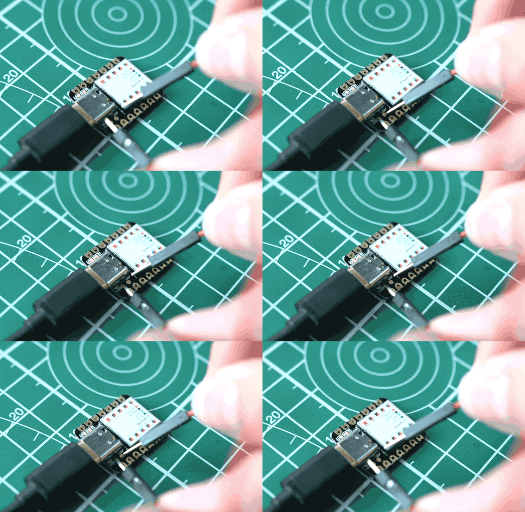
Sometimes the Seeed Studio XIAO SAMD21 port may disappear when user programming process fails. we can solve this problem by the following operation:
- Connect the Seeed Studio XIAO SAMD21 to your computer.
- Use tweezers or short lines to short the RST pins in the diagram twice.
- The orange LED lights flicker on and light up.
At this point, the chip enters Bootloader mode and the burn port appears again. Because the samd21 chip has two partitions, one is the Bootloader and the other is the user program. The product will burn a bootloader code in the system memory when it leaves the factory. We can switch modes by performing the above steps.
For XIAO SAMD21 Plus
Connect the XIAO SAMD21 Plus to your computer. Press the Reset button twice consecutively to enter Bootloader Mode.
Reset
If you want to reset the Seeed Studio XIAO SAMD21 , perform the following steps:
- Connect the Seeed Studio XIAO SAMD21 to your computer.
- Use tweezers or short lines to short the RST pins only once
- The orange LED lights flicker on and light up.
Please note: The behavior of the built-in LED is reversed to the one on an Arduino. On the Seeed Studio XIAO SAMD21 , the pin has to be pulled low, whereas on other micro-controllers it has to be pulled high.
Interrupt
All pins on Seeed Studio XIAO SAMD21 support interrupts, but two pins cannot be used at the same time: 5 pin and 7 pin. For more detail about Interrupt please check here.
Getting Started
Hardware
| Seeed Studio XIAO SAMD21 | Seeed Studio XIAO SAMD21 Plus |
|---|---|
| |
Materials required
- Seeed Studio XIAO SAMD21 x1
- Computer x1
- USB Type-C cable x1
Some USB cables can only supply power and cannot transfer data. If you don't have a usb cable or don't know if your usb cable can transmit data, you can check seeed USB type C support USB 3.1.
-
Step 1. Prepare a Seeed Studio XIAO SAMD21 and a Type-C cable.
-
Step 2. Connect the Seeed Studio XIAO SAMD21 to your computer.Then the yellow power LED should go on.
Software
If this is your first time using Arduino, we highly recommend you to refer to Getting Started with Arduino
- Step 1. You need to Install an Arduino Software.
Launch the Arduino application
Double-click the Arduino application (arduino.exe) you have previously downloaded.
If the Arduino Software loads in a different language, you can change it in the preferences dialog. See the Arduino Software (IDE) page for details.
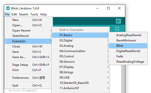
- Step 2. Open the Blink example
Open the LED blink example sketch: File > Examples >01.Basics > Blink.
- Step 3. Add Seeeduino to your Arduino IDE
Click on File > Preference, and fill Additional Boards Manager URLs with the url below:
https://files.seeedstudio.com/arduino/package_seeeduino_boards_index.json
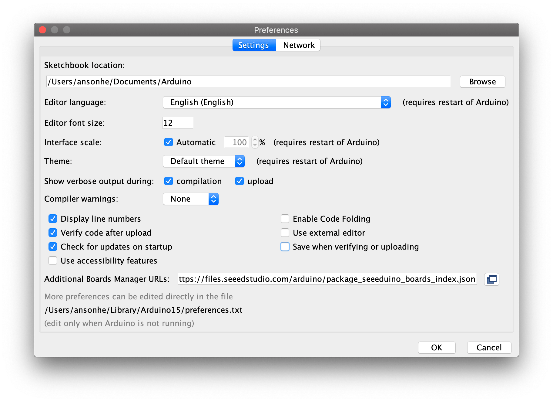
Click Tools-> Board-> Boards Manager..., print keyword "Seeed Studio XIAO SAMD21" in the searching blank. Here comes the Seeed SAMD Boards. Install it.

XIAO SAMD21 Blink
- Step 4. Select your board and port
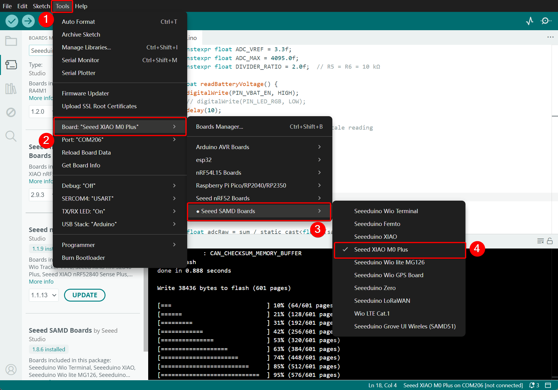
After installing the board, click Tools-> Board, find Seeed Studio XIAO and select it. Now you have already set up the board of Seeed Studio XIAO SAMD21 for Arduino IDE.

Select the serial device of the Arduino board from the Tools | Serial Port menu. This is likely to be COM3 or higher (COM1 and COM2 are usually reserved for hardware serial ports). To find out, you can disconnect your Arduino board and re-open the menu; the entry that disappears should be the Arduino board. Reconnect the board and select that serial port.

- Step 5.Upload the program
Now, simply click the Upload button in the environment. Wait a few seconds and if the upload is successful, the message "Done uploading." will appear in the status bar.
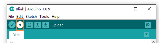
A few seconds after the upload finishes, you should see the pin 13 (L) LED on the board start to blink (in orange). If it does, congratulations! You've gotten Arduino up-and-running. If you have problems, please see the troubleshooting suggestions.
The maximum flash size is 8 KB. For more information, refer to the ATSAMD21G18A-MU datasheet in the resources section.
XIAO SAMD21 Plus Blink
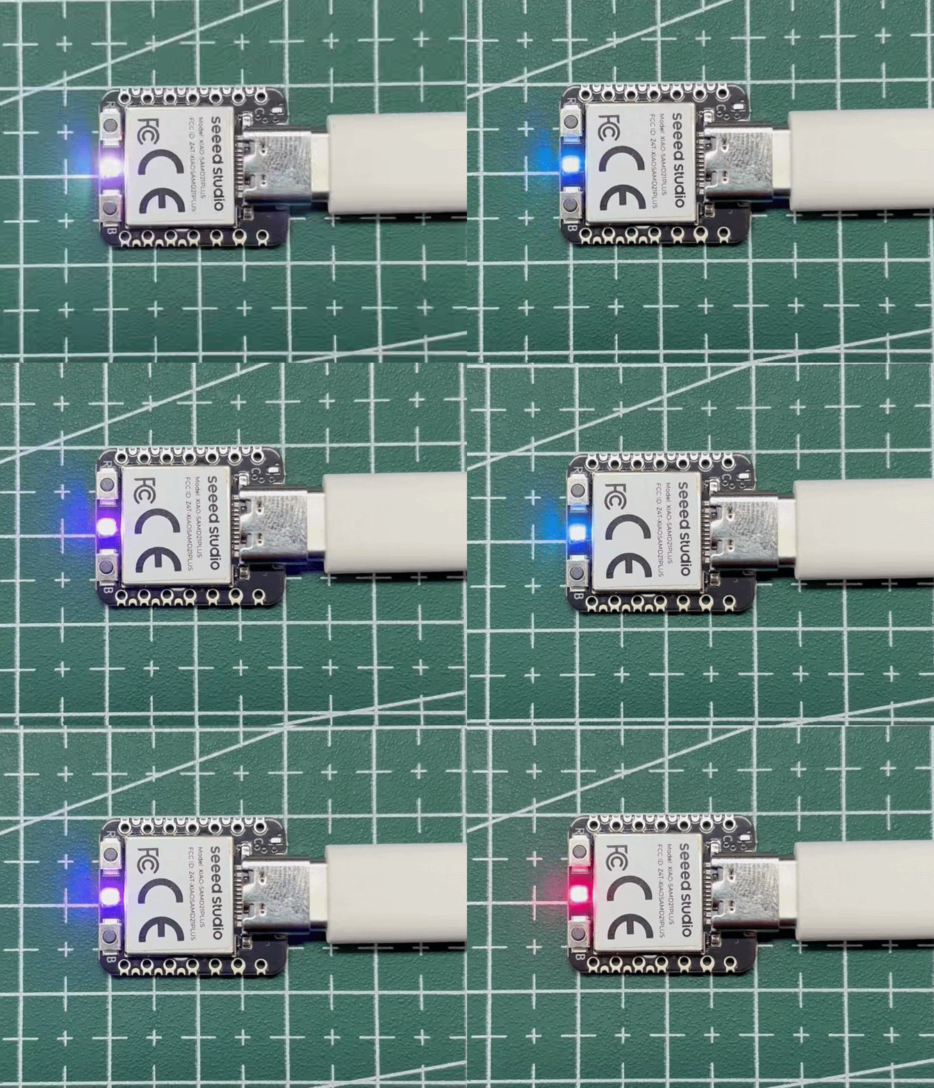
On the XIAO SAMD21 Plus, the L (LED) pin has been removed. It is replaced by the RGB_LED, which is controlled via pin PA27.
‑ Change the target board to XIAO M0 Plus.
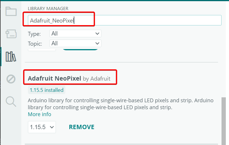
- Install the Adafruit_NeoPixel library and update it to the latest version.
‑ Replace the code with the snippet below. RGB_LED's data pin is PA27 (PIN_NEOPIXEL). The power-control pin is D11 — please add '#define NEOPIXEL_POWER 11' to your sketch.
The RGB LEDs may cause eye strain or injury if operated at excessive brightness; proper eye protection is recommended.
#include <Adafruit_NeoPixel.h>
#define NEOPIXEL_POWER 11

#define NUMPIXELS 1

Adafruit_NeoPixel pixels(NUMPIXELS, PIN_NEOPIXEL, NEO_GRB + NEO_KHZ800);

void setup() {
  pixels.begin();

  pinMode(NEOPIXEL_POWER, OUTPUT);
  digitalWrite(NEOPIXEL_POWER, HIGH);

// Set overall brightness (0~255)
// Recommended eye-friendly range: 10~50
  pixels.setBrightness(50);
}


void loop() {

  pixels.clear();
  pixels.setPixelColor(0, pixels.Color(15, 25, 205));
  pixels.show();
  delay(400);


  pixels.clear();
  pixels.setPixelColor(0, pixels.Color(103, 25, 205));
  pixels.show();
  delay(400);


  pixels.clear();
  pixels.setPixelColor(0, pixels.Color(233, 242, 205));
  pixels.show();
  delay(400);


  pixels.clear();
  pixels.setPixelColor(0, pixels.Color(233, 23, 23));
  pixels.show();
  delay(400);


  pixels.clear();
  pixels.setPixelColor(0, pixels.Color(12, 66, 101));
  pixels.show();
  delay(400);


  pixels.clear();
  pixels.show();
  delay(500);
}
‑ Click Upload to flash the program. Once completed, the RGB‑LED will light up.
The maximum flash size is 8 KB. For more information, refer to the ATSAMD21G18A-MU datasheet in the resources section.
Pin Multiplexing
We don't need to configure the pins ourselves, after using the pins, you can call a function directly.
Digital Input and Output
- Use pin 6 as the digital pin:
const int buttonPin = 6;     // the number of the pushbutton pin
const int ledPin =  13;      // the number of the LED pin

int buttonState = 0;         // variable for reading the pushbutton status

void setup() {
  // initialize the LED pin as an output:
  pinMode(ledPin, OUTPUT);
  // initialize the pushbutton pin as an input:
  pinMode(buttonPin, INPUT);
}

void loop() {
  // read the state of the pushbutton value:
  buttonState = digitalRead(buttonPin);

  // check if the pushbutton is pressed. If it is, the buttonState is HIGH:
  if (buttonState == HIGH) {
    // turn LED on:
    digitalWrite(ledPin, HIGH);
  } else {
    // turn LED off:
    digitalWrite(ledPin, LOW);
  }
}
AnalogRead
- Use pin 6 as the analog pin:
void setup() {
  // declare the ledPin as an OUTPUT:
  pinMode(ledPin, OUTPUT);
}

void loop() {
  // read the value from the sensor:
  sensorValue = analogRead(sensorPin);
  // turn the ledPin on
  digitalWrite(ledPin, HIGH);
  // stop the program for <sensorValue> milliseconds:
  delay(sensorValue);
  // turn the ledPin off:
  digitalWrite(ledPin, LOW);
  // stop the program for for <sensorValue> milliseconds:
  delay(sensorValue);
}
Serial
- Use pin 6 as the TX pin of UART(RX pin of UART is pin 7):
void setup() {
    Serial1.begin(115200);
    while (!Serial);
}

void loop() {
    Serial1.println("Hello,World");
    delay(1000);
}
I2C
- Use pin 5 as the SCL pin of IIC(SDA pin of IIC is pin 4):
// Wire Master Writer
// by Nicholas Zambetti <http://www.zambetti.com>

// Demonstrates use of the Wire library
// Writes data to an I2C/TWI slave device
// Refer to the "Wire Slave Receiver" example for use with this

// Created 29 March 2006

// This example code is in the public domain.


#include <Wire.h>

void setup()
{
  Wire.begin(); // join i2c bus (address optional for master)
}

byte x = 0;

void loop()
{
  Wire.beginTransmission(4); // transmit to device #4
  Wire.write("x is ");        // sends five bytes
  Wire.write(x);              // sends one byte
  Wire.endTransmission();    // stop transmitting
  x++;
  delay(500);
}
SPI
- Use pin 8 as the SCK pin of SPI(MISO pin of SPI is pin 9,MOSI pin of SPI is pin 10):
#include <SPI.h>
const int CS = 7;
void setup (void) {
   digitalWrite(CS, HIGH); // disable Slave Select
   SPI.begin ();
   SPI.setClockDivider(SPI_CLOCK_DIV8);//divide the clock by 8
}

void loop (void) {
   char c;
   digitalWrite(CS, LOW); // enable Slave Select
   // send test string
   for (const char * p = "Hello, world!\r" ; c = *p; p++) {
      SPI.transfer (c);
   }
   digitalWrite(CS, HIGH); // disable Slave Select
   delay(2000);
}
QTouch
For how to use QTouch, we provide an example project: How to Make a Fruit Piano on Seeed Studio XIAO SAMD21 ’s Q-Touch Function.
Analog Input and Output
While it still has PWM-based "analog outputs", the SAMD21 also features true analog output in the form of a digital-to-analog converter (DAC). This module can produce an analog voltage between 0 and 3.3V. It can be used to produce audio with more natural sound, or as a kind of "digital potentiometer" to control analog devices.
The DAC is only available on the Arduino pin A0, and is controlled using analogWrite(A0, <value>). The DAC can be set up to 10-bit resolution (make sure to call analogWriteResolution(10) in your setup), which means values between 0 and 1023 will set the voltage to somewhere between 0 and 3.3V.
In addition to the DAC, the SAMD21's ADC channels also stand apart from the ATmega328: they're equipped with up to 12-bit resolution. That means the analog input values can range from 0-4095, representing a voltage between 0 and 3.3V. To use the ADC's in 12-bit mode, make sure you call analogReadResolution(12) in your setup.
Serial Plotting the DAC
Here's an example that demonstrates both the DAC and the ADC. To set the experiment up, connect A0 to A1 -- we'll drive A0 with an analog voltage, then read it with A1. It's the simplest circuit we've ever put in a tutorial:
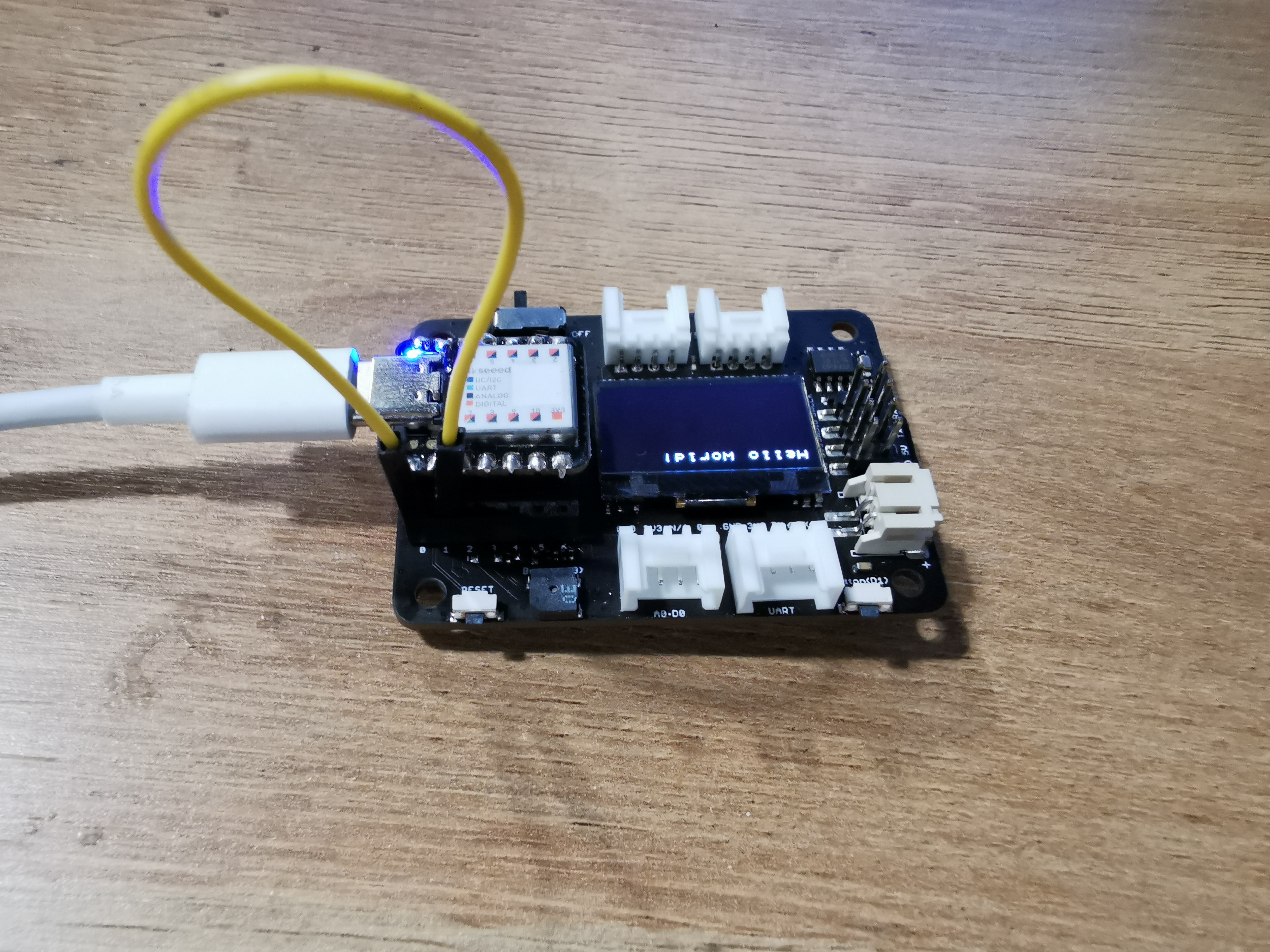
The Seeed Studio XIAO SAMD21 using the Seeed Studio XIAO SAMD21 expansion board
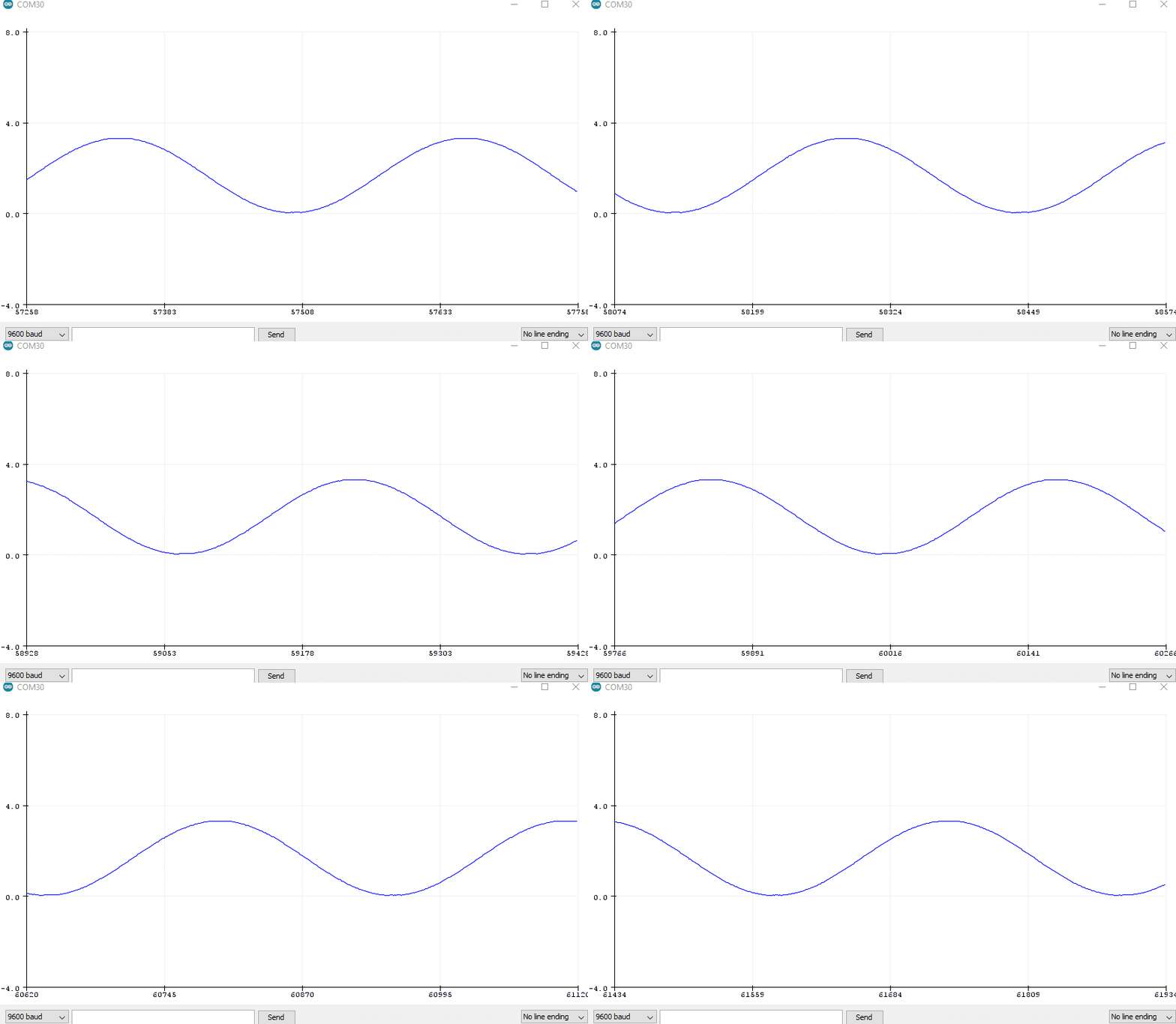
This sketch produces a sine wave output on A0, with values ranging from 0 to 3.3V. Then it uses A1 to read that output into its ADC, and convert it into a voltage between 0 and 3.3V.
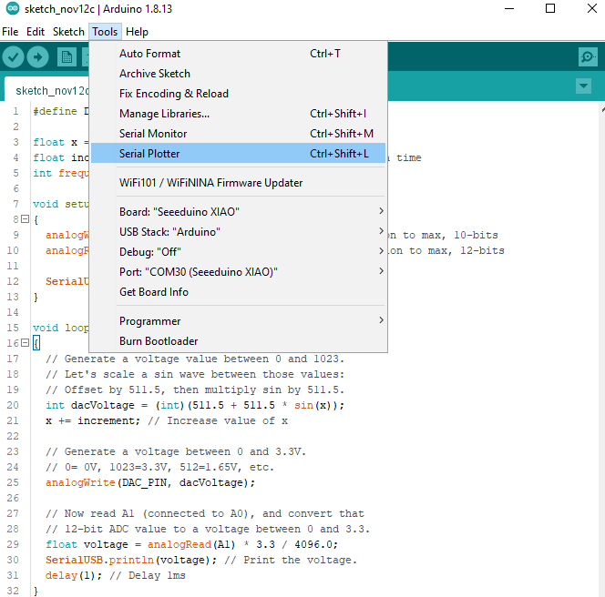
You can, of course, open the serial monitor to view the voltage values stream by. But if the the sine wave is hard to visualize through text, check out Arduino's new Serial Plotter, by going to Tools > Serial Plotter.
Thank you to Aleksei Tertychnyi for submitting the code, all related functionalities were developed and contributed by him.
#define DAC_PIN A0 // Make code a bit more legible
float x = 0; // Value to take the sin of
float increment = 0.02;  // Value to increment x by each time
// Frequency of sine wave is about 1.37 Hz

void setup()
{
  analogWriteResolution(10); // Set analog out resolution to max, 10-bits
  analogReadResolution(12); // Set analog input resolution to max, 12-bits

  Serial.begin(9600);
}

void loop()
{
  // Generate a voltage value between 0 and 1023.
  // Let's scale a sin wave between those values:
  // Offset by 511.5, then multiply sin by 511.5.
  int dacVoltage = (int)(511.5 + 511.5 * sin(x));
  x += increment; // Increase value of x

  // Generate a voltage between 0 and 3.3V.
  // 0= 0V, 1023=3.3V, 512=1.65V, etc.
  analogWrite(DAC_PIN, dacVoltage);

  // Now read A1 (connected to A0), and convert that
  // 12-bit ADC value to a voltage between 0 and 3.3.
  float voltage = analogRead(A1) * 3.3 / 4096.0;
  Serial.println(voltage); // Print the voltage.
  delay(1); // Delay 1ms
}
Result

Battery Usage
Only the XIAO SAMD21 Plus features a BAT battery connector on its back side, please take note.
The XIAO SAMD21 Plus is capable of using a 3.7V lithium battery as the power supply input. You can refer to the following diagram for the wiring method.
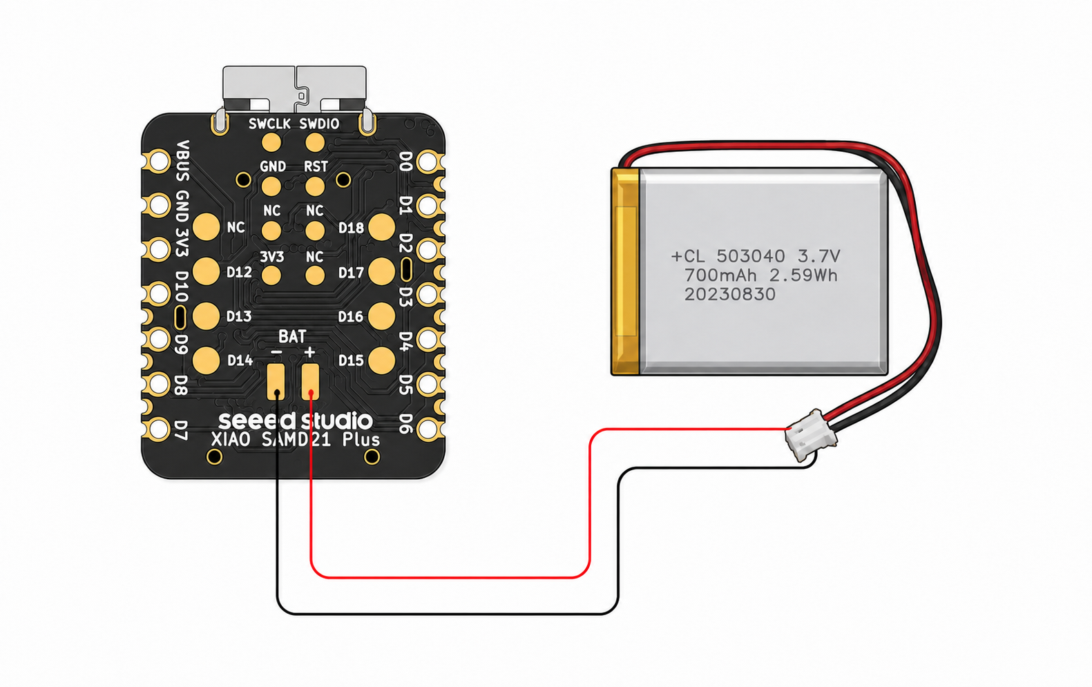
Please be careful not to short-circuit the positive and negative terminals and burn the battery and equipment when soldering. If the battery has power, never solder it onto the board, as this may burn out the circuit board. Short-circuiting while the circuit is powered on poses a significant risk; it is recommended to use an adapter.
Battery Voltage Reading Example
According to the schematic, the SGM40567-4.2XG/TR provides single-cell lithium battery charging with a charging current of approximately 200 mA. The Charge_LED blinks during charging.
Battery voltage measurement is controlled by the TPS22916CNYFPR load switch through PB2/VBAT_EN, reducing standby power consumption. The battery voltage is divided by two and measured through the PB3/AIN11_VBAT ADC pin.
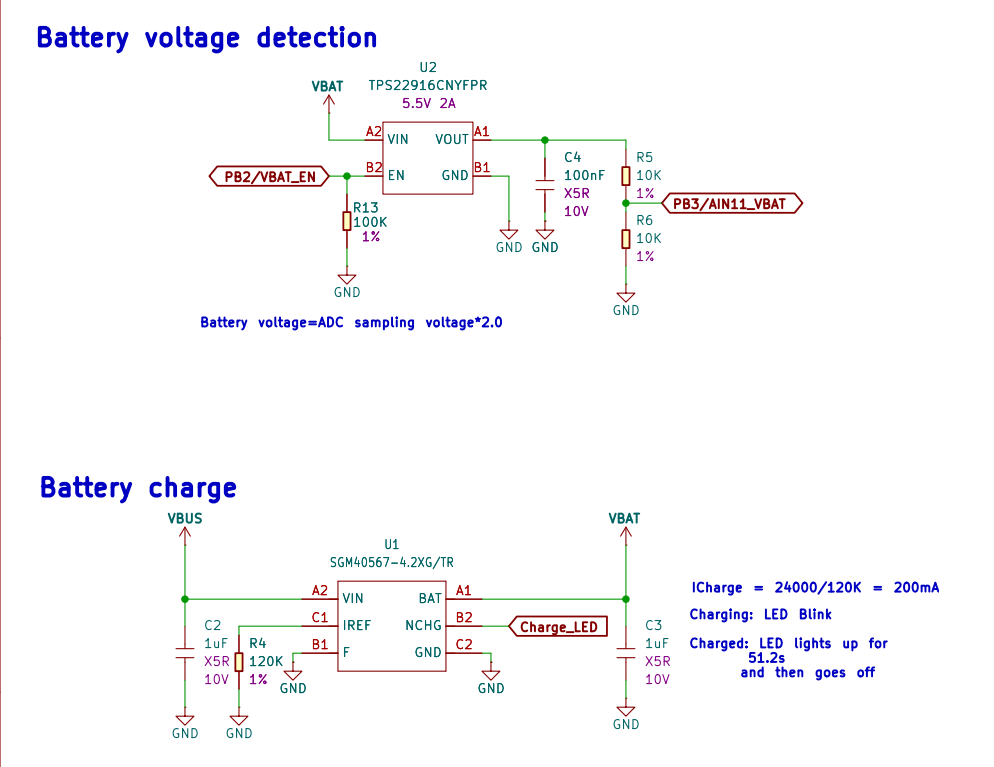
The battery voltage is measured using a resistor-divider circuit. The voltage read by the ADC is half of the actual battery voltage, so the software must multiply the ADC measurement by 2 to obtain the actual battery voltage.
In the Arduino core, PB02 and PB03 are mapped to pin numbers 31 and 32, respectively. Define them as follows:
// VBAT_EN on PB02
#define PIN_VBAT_EN  (31u)

// AIN11_VBAT on PB03
#define PIN_VBAT_ADC (32u)
Battery read example
constexpr float ADC_VREF = 3.3f;
constexpr float ADC_MAX = 4095.0f;
constexpr float DIVIDER_RATIO = 2.0f;  // R5 = R6 = 10 kΩ

float readBatteryVoltage() {
  digitalWrite(PIN_VBAT_EN, HIGH);
  delay(10);

  analogRead(PIN_VBAT_ADC);  // Discard a stale reading

  uint32_t sum = 0;
  constexpr int samples = 16;

  for (int i = 0; i < samples; i++) {
    sum += analogRead(PIN_VBAT_ADC);
    delay(2);
  }

  digitalWrite(PIN_VBAT_EN, LOW);

  float adcRaw = sum / static_cast<float>(samples);
  float adcVoltage = adcRaw * ADC_VREF / ADC_MAX;

  return adcVoltage * DIVIDER_RATIO;
}

void setup() {
  Serial.begin(115200);

  pinMode(PIN_VBAT_EN, OUTPUT);
  digitalWrite(PIN_VBAT_EN, LOW);

  analogReadResolution(12);  // SAMD21 ADC: 0–4095
}

void loop() {
  float batteryVoltage = readBatteryVoltage();

  Serial.print("Battery: ");
  Serial.print(batteryVoltage, 3);
  Serial.println(" V");

  delay(1000);
}
For low-power applications, disable BAT_EN after the battery voltage measurement is complete to reduce the quiescent power consumption caused by the voltage-divider resistors.
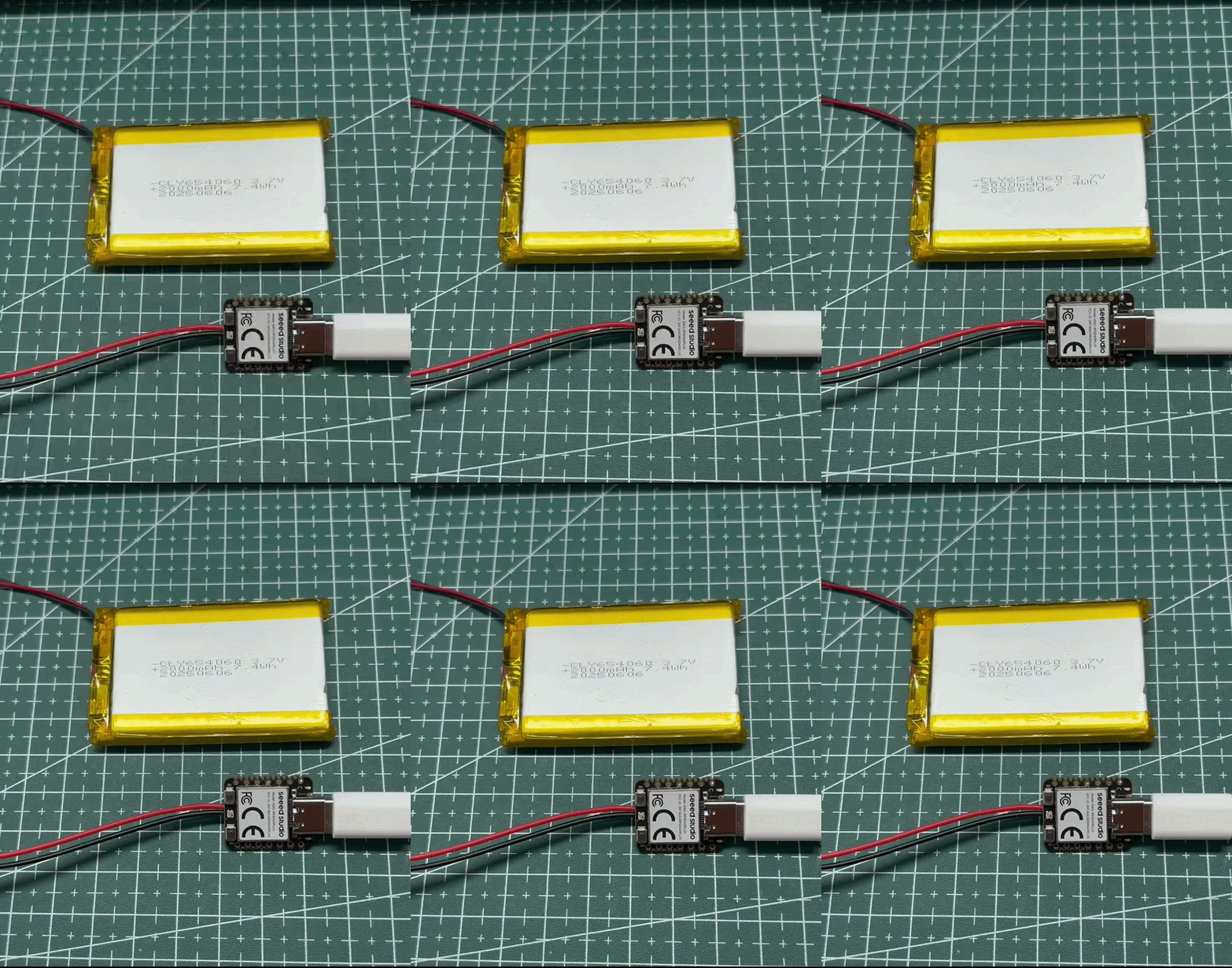
- The Charge_LED blinks while the battery is charging.
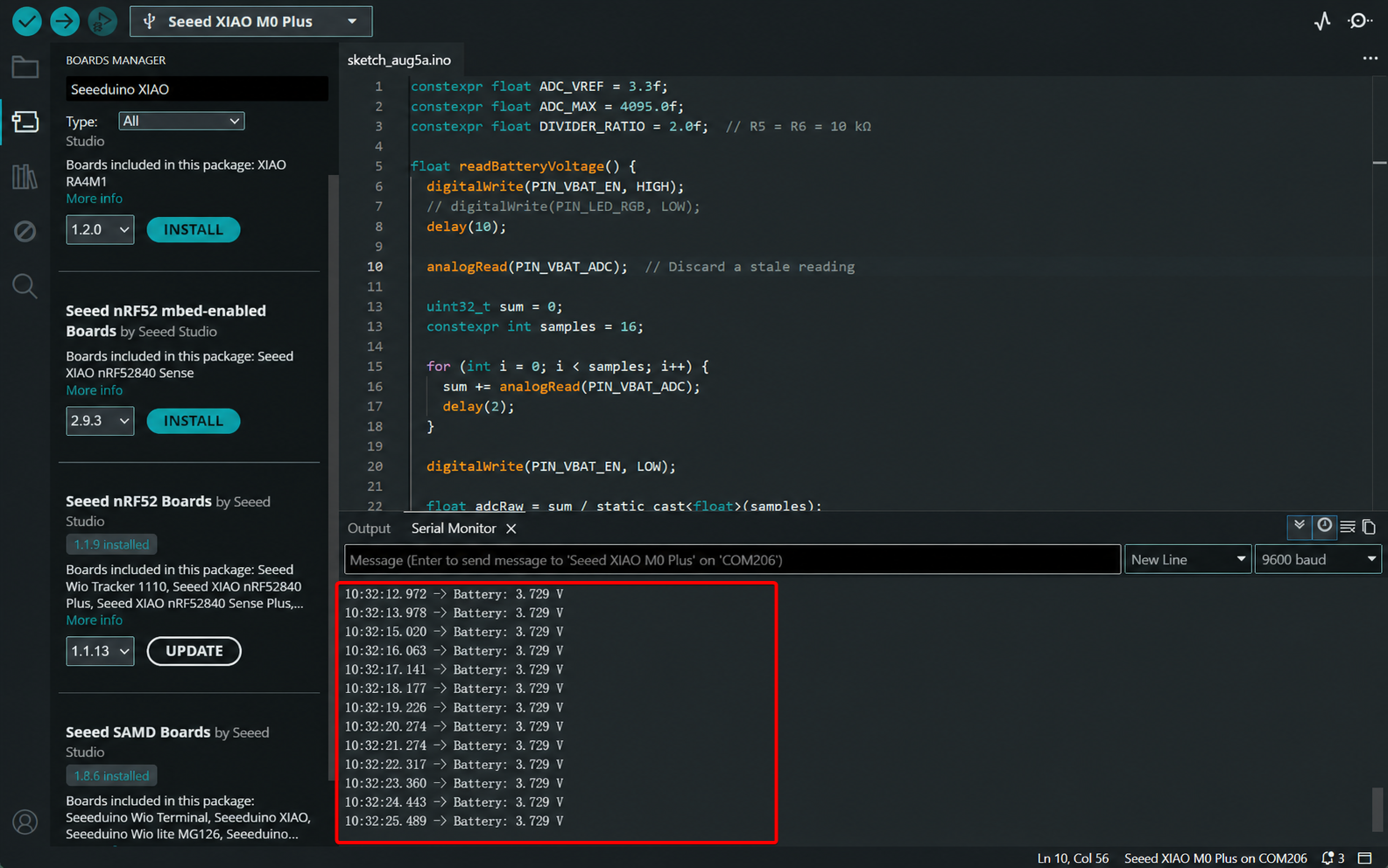
- Battery voltage measurement result: The measured voltage of a lithium-ion battery may differ from the nominal value printed on the battery. Always refer to the actual measured value.
The sample application
-
How to use Seeed Studio XIAO SAMD21 to log in to your Raspberry PI
-
How to unbrick a dead xiao using raspberry pi. Thanks John_Doe for sharing.
Resources
XIAO SAMD21
Hardware Design
- 📄[Datasheet] Atmel SAMD21G18 Datasheet
- 📄[Schematic] XIAO SAMD21 Schematic
- 🗃️[PCB Design Files]
- 🗃️[PCB Design Libraries]
- 📄[Pinout Sheet] XIAO SAMD21 Pinout Sheet
Mechanical Design
- 📄[2D Dimensions] XIAO Dimension in DXF
- 📄[3D Model] XIAO SAMD21 3D Model
Software & Tools
- 📄[Factory Firmware] XIAO SAMD21 Factory Firmware
XIAO SAMD21 Plus
Hardware Design
- 📄[Datasheet] Atmel SAMD21G18 Datasheet
- 📄[Schematic] XIAO SAMD21 Plus Schematic
- 🗃️[PCB Design Files]
- 🗃️[PCB Design Libraries]
- 📄[Pinout Sheet] XIAO SAMD21 Plus Pinout Sheet
Mechanical Design
- 📄[2D Dimensions] XIAO Dimension in DXF
Course Resources
Tech Support & Product Discussion
Thank you for choosing our products! We are here to provide you with different support to ensure that your experience with our products is as smooth as possible. We offer several communication channels to cater to different preferences and needs.