Getting Started with Seeed Studio XIAO ESP32C3
Introduction
Seeed Studio XIAO ESP32C3 is an IoT mini development board based on the Espressif ESP32-C3 WiFi/Bluetooth dual-mode chip, featuring a 32-bit RISC-V CPU that delivers powerful computing performance with its efficient architecture. It has excellent radio frequency performance, supporting IEEE 802.11 b/g/n WiFi, and Bluetooth 5 (BLE) protocols. This board comes included with an external antenna to increase the signal strength for your wireless applications. It also has a small and exquisite form-factor combined with a single-sided surface-mountable design. It is equipped with rich interfaces and has 11 digital I/O that can be used as PWM pins and 4 analog I/O that can be used as ADC pins. It supports four serial interfaces such as UART, I2C and SPI. There is also a small reset button and a bootloader mode button on the board. XIAO ESP32C3 is fully compatible with the Grove Shield for Seeeduino XIAO and Seeeduino XIAO Expansion board except for the Seeeduino XIAO Expansion board, the SWD spring contacts on the board will not be compatible.
With regard to the features highlighted above, XIAO ESP32C3 is positioned as a high-performance, low-power, cost-effective IoT mini development board, suitable for low-power IoT applications and wireless wearable applications.
This wiki will show you how you can quickly get started with XIAO ESP32C3!
Specifications
| Parameter | Description |
|---|---|
| Processor | ESP32-C3 SoC RISC-V single-core 32-bit chip processor with a four-stage pipeline that operates at up to 160 MHz |
| Wireless | Complete 2.4GHz Wi-Fi subsystem Bluetooth Low Energy 5.0/ Bluetooth Mesh |
| On-chip Memory | 400KB SRAM & 4MB Flash |
| Interface | 1x UART 1x IIC 1x SPI 11x GPIO(PWM) 4x ADC 1x Reset button 1x Boot button |
| Dimensions | 21 x 17.8mm |
| Power(Typ.) | Max 3.3V Output Current: 500mA Test Condition: BAT Pin Input @ 3.8V Source Capability: 3A Charging current: 380mA(Fast) / 40mA(Trickle) Input voltage (VIN): 5V Input voltage (BAT): 3.7V |
| Deep Sleep Power Consumption | Deep Sleep Mode: 44 μA |
| Wi-Fi Enabled Power Consumption | Active Mode: 75 mA Modem-sleep Mode: 25 mA Light-sleep Mode: 4 mA |
| BLE Enabled Power Consumption | Modem-sleep Mode: 27 mA Light-sleep Mode: 10 mA |
| Working Temperature | -40°C ~ 85°C |
Features
- Powerful CPU: ESP32-C3, 32bit RISC-V singlecore processor that operates at up to 160 MHz
- Complete WiFi subsystem: Complies with IEEE 802.11b/g/n protocol and supports Station mode, SoftAP mode, SoftAP + Station mode, and promiscuous mode
- Bluetooth LE subsystem: Supports features of Bluetooth 5 and Bluetooth mesh
- Ultra-Low Power: Deep sleep power consumption is about 43μA
- Better RF performance: External RF antenna included
- Battery charging chip: Supports lithium battery charge and discharge management
- Rich on-chip resources: 400KB of SRAM, and 4MB of on-board flash memory
- Ultra small size: As small as a thumb(21x17.8mm) XIAO series classic form-factor for wearable devices and small projects
- Reliable security features: Cryptographic hardware accelerators that support AES-128/256, Hash, RSA, HMAC, digital signature and secure boot
- Rich interfaces: 1xI2C, 1xSPI, 2xUART, 11xGPIO(PWM), 4xADC, 1xJTAG bonding pad interface
- Single-sided components, surface mounting design
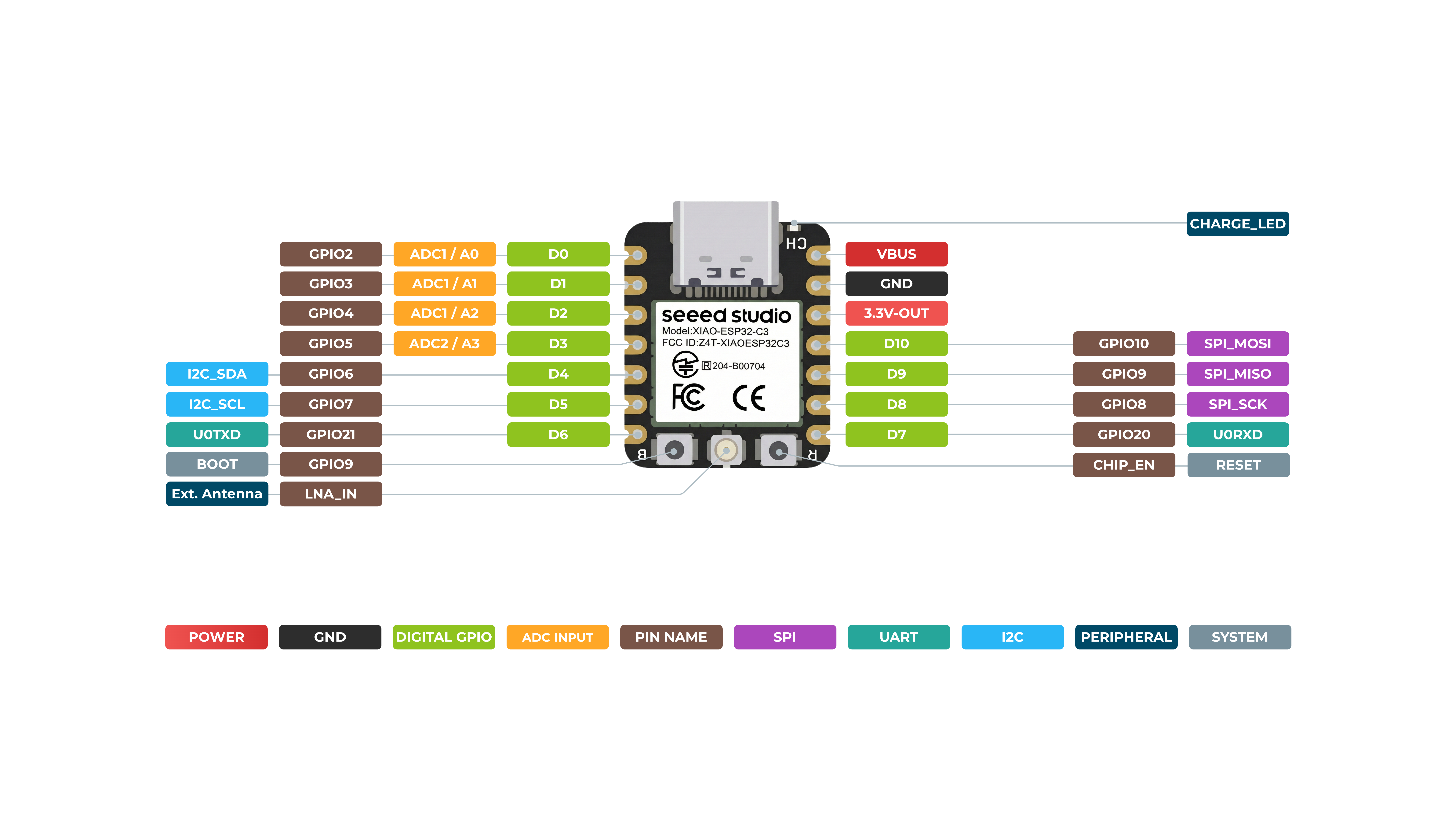
Hardware overview
*A3(GP105) - Uses ADC2, which may become inoperative due to false sampling signals. For reliable analog reads, use ADC1(A0/A1/A2) instead. Refer to the ESP32-C3 datasheet.
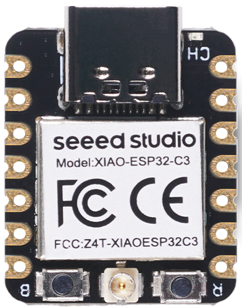
Front
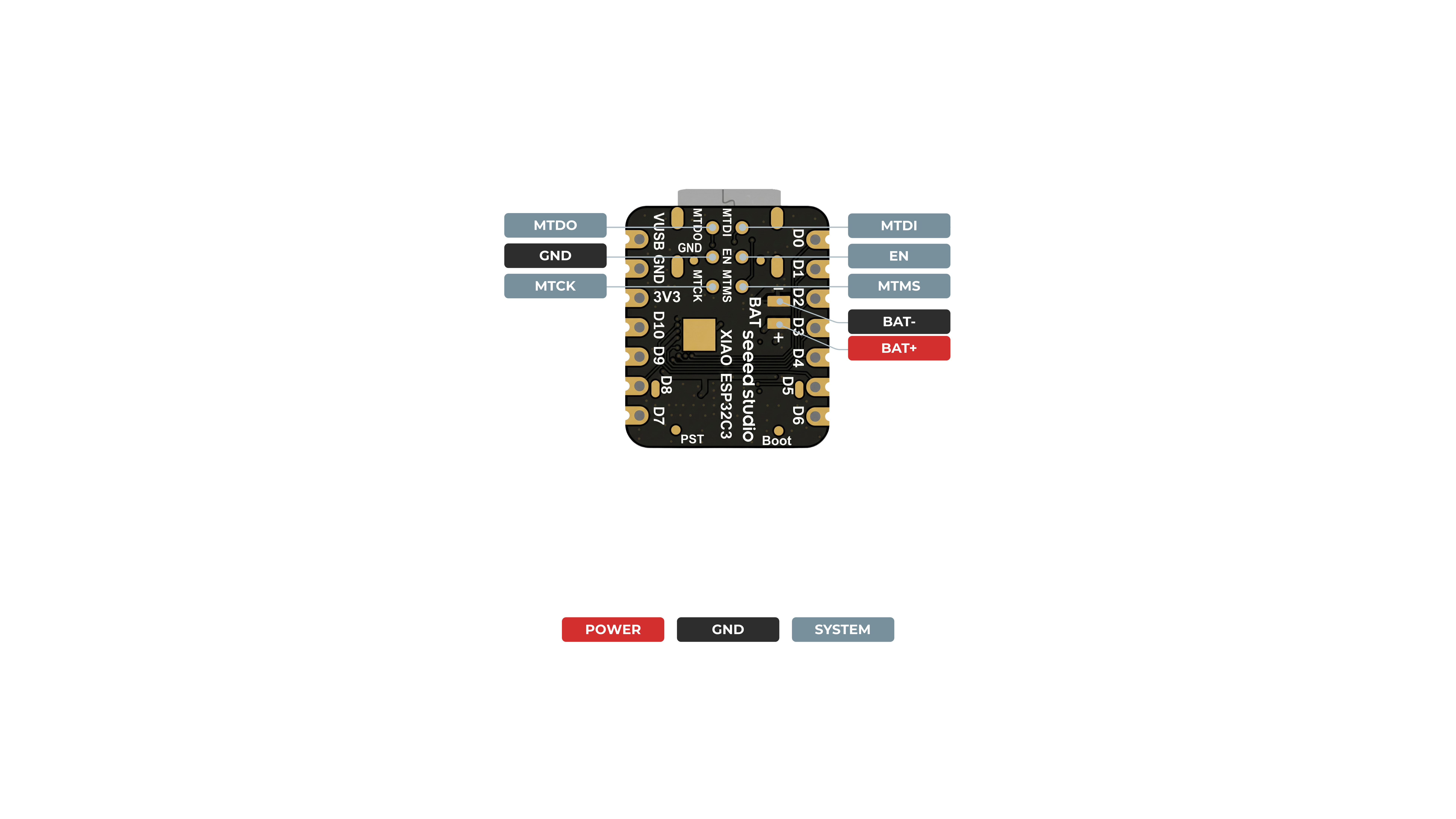
Back
Pin Map
| XIAO Pin | Function | Chip Pin | Alternate Functions | Description |
|---|---|---|---|---|
| 5V | VBUS | Power Input/Output | ||
| GND | ||||
| 3V3 | 3V3_OUT | Power Output | ||
| D0 | Analog | GPIO2 | ADC1_CH2, | GPIO, ADC |
| D1 | Analog | GPIO3 | ADC1_CH3 | GPIO, ADC |
| D2 | Analog | GPIO4 | ADC1_CH4, FSPIHD, MTMS | GPIO, ADC |
| D3 | Analog | GPIO5 | ADC2_CH0, FSPIWP, MTDI | GPIO, ADC |
| D4 | SDA | GPIO6 | FSPICLK, MTCK | GPIO, I2C Data |
| D5 | SCL | GPIO7 | FSPID, MTDO | GPIO, I2C Clock |
| D6 | TX | GPIO21 | U0TXD | GPIO, UART Transmit |
| D7 | RX | GPIO20 | U0RXD | GPIO, UART Receive |
| D8 | SCK | GPIO8 | GPIO, SPI Clock | |
| D9 | MISO | GPIO9 | GPIO, SPI Data | |
| D10 | MOSI | GPIO10 | FSPICS0 | GPIO, SPI Data |
| MTDO | GPIO7 | JTAG | ||
| MTDI | GPIO5 | JTAG, ADC | ||
| MTCK | GPIO6 | JTAG, ADC | ||
| MTMS | GPIO4 | JTAG, ADC | ||
| Reset | CHIP_EN | EN | ||
| Boot | GPIO9 | Enter Boot Mode | ||
| U.FL-R-SMT1 | LNA_IN | UFL antenna | ||
| Light | VCC_3V3 | CHG-LED |
Power Pins
- 5V - This is 5v out from the USB port. You can also use this as a voltage input but you must have some sort of diode (schottky, signal, power) between your external power source and this pin with anode to battery, cathode to 5V pin.
- 3V3 - This is the regulated output from the onboard regulator. You can draw 700mA
- GND - Power/data/signal ground
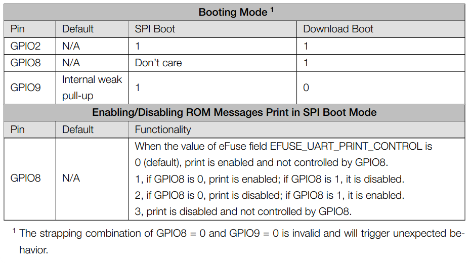
Strapping Pins
According to the chip manual of ESP32C3, GPIO2, GPIO8 and GPIO9 in the chip are Strapping Pins, the high and low level configurations of these pins may allow the chip to enter into different Boot modes, please pay attention to this point when you use these pins, otherwise it may prevent your XIAO from uploading or executing the program all the time.
Getting started
First, we are going to connect XIAO ESP32C3 to the computer, connect an LED to the board and upload a simple code from Arduino IDE to check whether the board is functioning well by blinking the connected LED.
Hardware Preparation
You need to prepare the following:
- 1 x Seeed Studio XIAO ESP32C3
- 1 x Computer
- 1 x USB Type-C cable
Some USB cables can only supply power and cannot transfer data. If you don't have a USB cable or don't know if your USB cable can transmit data, you can check Seeed USB Type-C support USB 3.1.
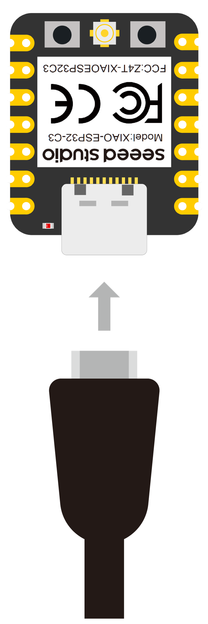
- Step 1. Connect XIAO ESP32C3 to your computer via a USB Type-C cable.
- Step 2. Connect an LED to D10 pin as follows
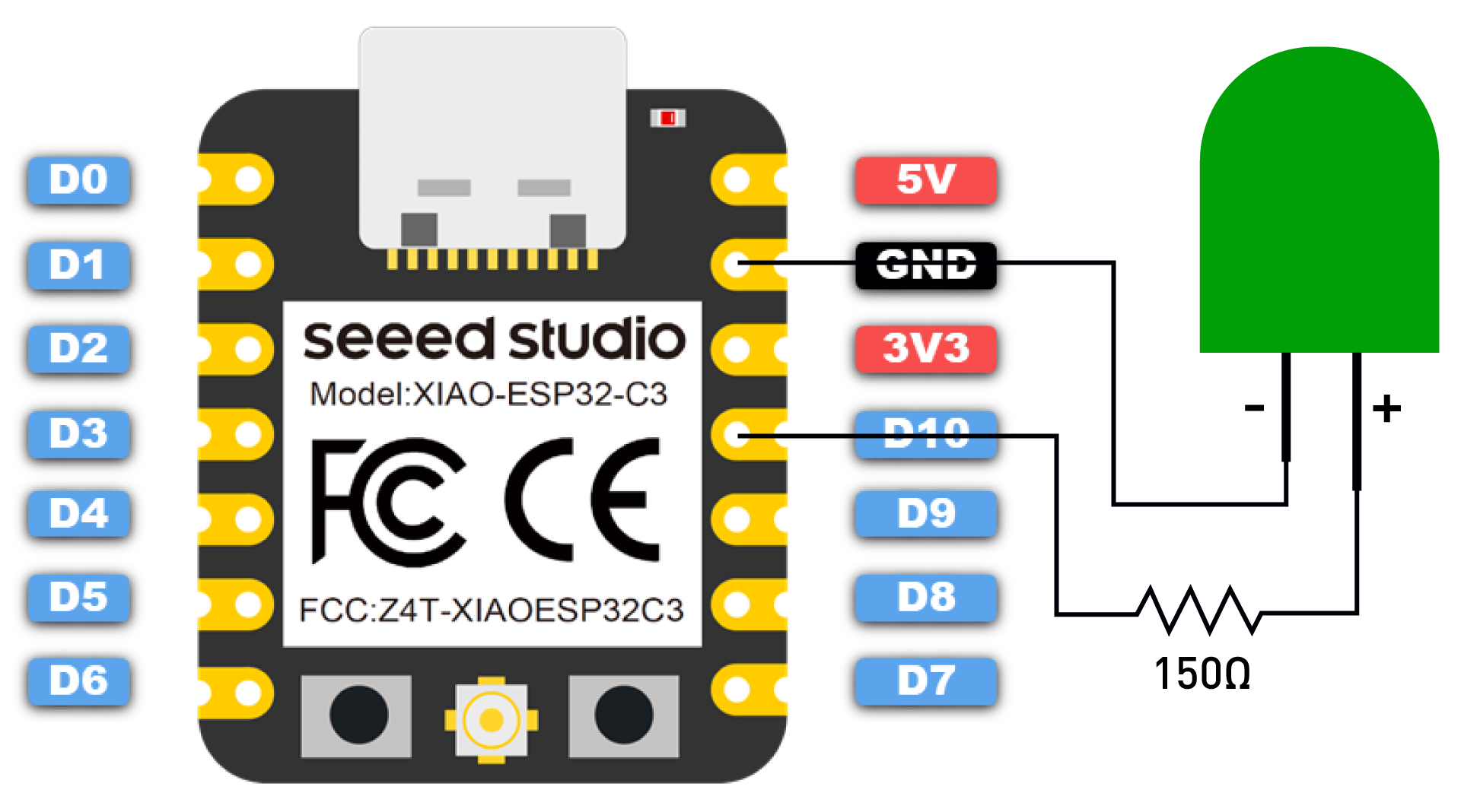
Note: Make sure to connect a resistor (about 150Ω) in series to limit the current through the LED and to prevent excess current that can burn out the LED
Software Preparation
- Step 1. Download and Install the latest version of Arduino IDE according to your operating system

-
Step 2. Launch the Arduino application
-
Step 3. Add ESP32 board package to your Arduino IDE
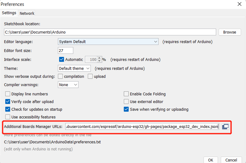
Navigate to File > Preferences, and fill "Additional Boards Manager URLs" with the url below: https://jihulab.com/esp-mirror/espressif/arduino-esp32.git
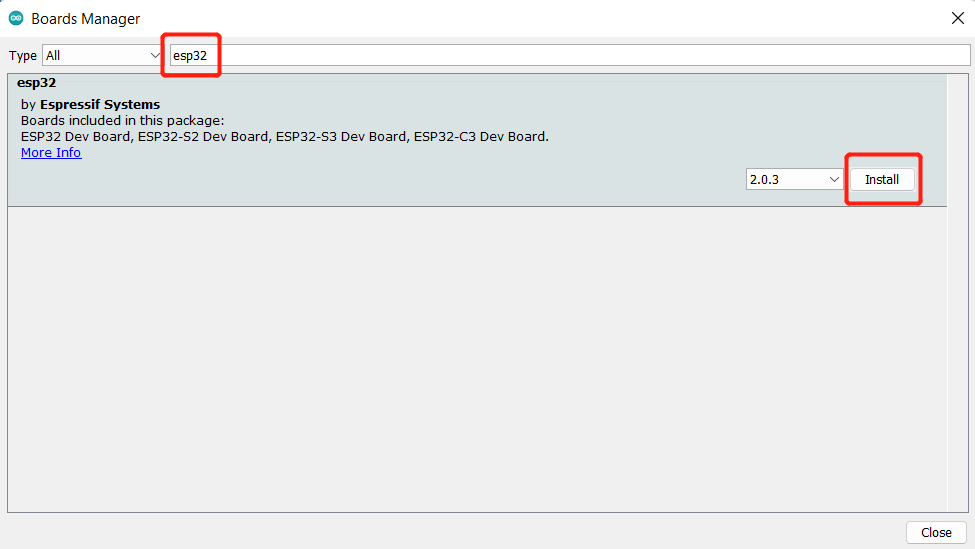
Navigate to Tools > Board > Boards Manager..., type the keyword "esp32" in the search box, select the latest version of esp32, and install it.
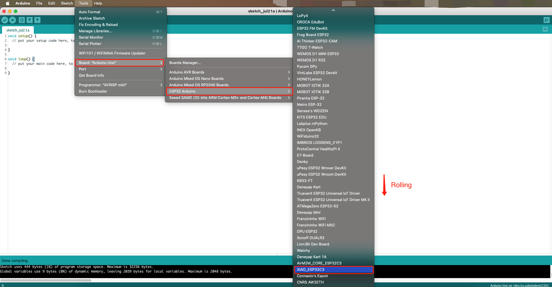
- Step 4. Select your board and port
Board
Navigate to Tools > Board > ESP32 Arduino and select "XIAO_ESP32C3". The list of board is a little long and you need to roll to the buttom to reach it.
Port
Navigate to Tools > Port and select the serial port name of the connected XIAO ESP32C3. This is likely to be COM3 or higher (COM1 and COM2 are usually reserved for hardware serial ports).
Run your first Blink program
- Step 1. Copy the below code to Arduino IDE
Make sure your D10 is connected to an LED as shown in the diagram above.
// define led according to pin diagram in article
const int led = D10; // there is no LED_BUILTIN available for the XIAO ESP32C3.

void setup() {
  // initialize digital pin led as an output
  pinMode(led, OUTPUT);
}

void loop() {
  digitalWrite(led, HIGH);   // turn the LED on
  delay(1000);               // wait for a second
  digitalWrite(led, LOW);    // turn the LED off
  delay(1000);               // wait for a second
}
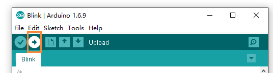
- Step 2. Click the Upload button to upload the code to the board
Once uploaded, you will see the connected LED blinking with a 1-second delay between each blink. This means the connection is successful and now you can explore more projects with XIAO ESP32C3!
Battery Usage
The XIAO ESP32C3 is capable of using a 3.7V lithium battery as the power supply input. You can refer to the following diagram for the wiring method.
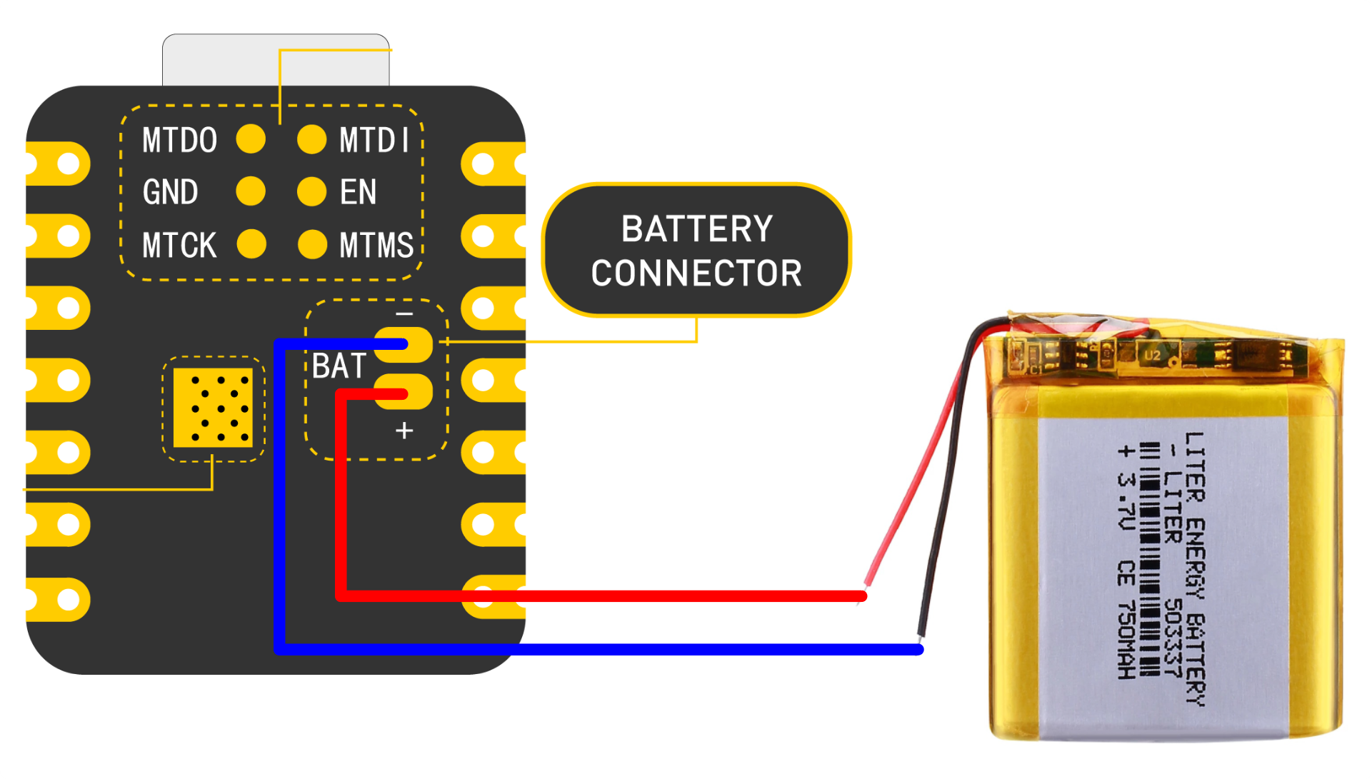
Please be careful not to short-circuit the positive and negative terminals and burn the battery and equipment when soldering.
Instructions on the use of batteries:
- Please use qualified batteries that meet the specifications.
- XIAO can be connected to your computer device via data cable while using the battery, rest assured that XIAO has a built-in circuit protection chip, which is safe.
- The XIAO ESP32C3 will not have any LED on when it is battery powered (unless you have written a specific program), please do not judge whether the XIAO ESP32C3 is working or not by the condition of the LED, please judge it reasonably by your program.
- Sorry, we currently have no way to help you check the remaining battery level through software (because there are no more chip pins available), you need to charge the battery regularly or use a multimeter to check the battery level.
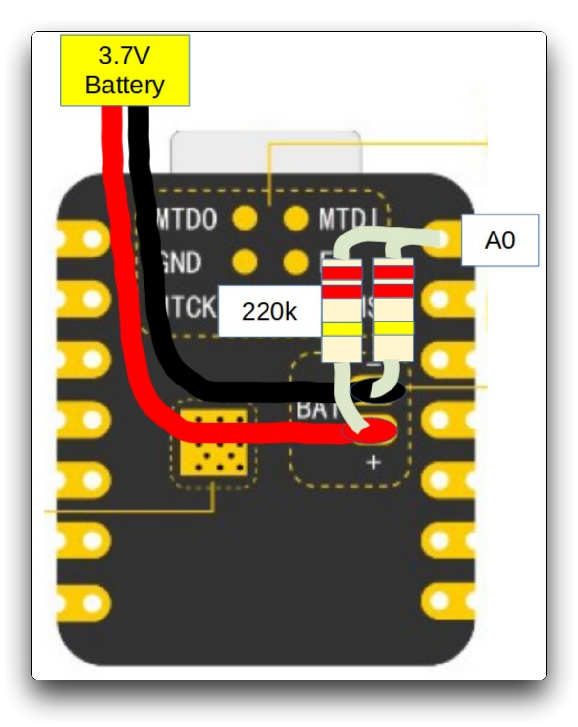
Check the battery voltage
Due to the limitation of the number of pins in the ESP32C3, engineers had no extra pins to allocate to the battery for voltage measurement in order to ensure that the XIAO ESP32C3 has the same number of GPIOs as the other XIAO series available.
But if you prefer to use a separate pin for battery voltage measurement, you can refer to the genius operation of msfujino. We would also like to give a special thanks to msfujino for all the experience and efforts shared for the XIAO ESP32C3.
The basic operating idea is: The battery voltage was divided by 1/2 with 200k and connected to the A0 port so that the voltage could be monitored.
The datasheet says nominally 2500mV full scale AD conversion, but there is a large variation from chip to chip, actually ±10%. My chip was 2700mV full scale.
Fortunately, the calibrated correction value for each chip is written in the fuse area, and by using the function analogReadMilliVolts(), I can read the corrected voltage value without doing anything special.
The result of AD conversion and the voltage measured by the multimeter agree well with each other with an error of about 5 mV, which is not a problem in practical use.
In addition, during communication in particular, spike-like errors occurred, which had to be averaged out 16 times to remove them.
The following is the procedure to test the battery voltage.
void setup() {
  Serial.begin(115200);
  pinMode(A0, INPUT);         // ADC
}

void loop() {
  uint32_t Vbatt = 0;
  for(int i = 0; i < 16; i++) {
    Vbatt = Vbatt + analogReadMilliVolts(A0); // ADC with correction
  }
  float Vbattf = 2 * Vbatt / 16 / 1000.0;     // attenuation ratio 1/2, mV --> V
  Serial.println(Vbattf, 3);
  delay(1000);
}
The above is from Seeed Studio forum user msfujino, originally posted at: https://forum.seeedstudio.com/t/battery-voltage-monitor-and-ad-conversion-for-xiao-esp32c/267535. We recommend that you have good hands-on skills and better soldering skills before attempting to measure battery voltage based on the above, and be cautious of dangerous actions such as shorting out batteries.
Deep sleep mode and wake-up
The XIAO ESP32C3 is designed to support deep sleep mode and wake-up functions. For the use of these two functions, we provide the following usage examples.
#define BUTTON_PIN_BITMASK 0x200000000 // 2^33 in hex

RTC_DATA_ATTR int bootCount = 0;

/*
Method to print the reason by which ESP32
has been awaken from sleep
*/
void print_wakeup_reason(){
  esp_sleep_wakeup_cause_t wakeup_reason;

  wakeup_reason = esp_sleep_get_wakeup_cause();

  switch(wakeup_reason)
  {
    case ESP_SLEEP_WAKEUP_EXT0 : Serial.println("Wakeup caused by external signal using RTC_IO"); break;
    case ESP_SLEEP_WAKEUP_EXT1 : Serial.println("Wakeup caused by external signal using RTC_CNTL"); break;
    case ESP_SLEEP_WAKEUP_TIMER : Serial.println("Wakeup caused by timer"); break;
    case ESP_SLEEP_WAKEUP_TOUCHPAD : Serial.println("Wakeup caused by touchpad"); break;
    case ESP_SLEEP_WAKEUP_ULP : Serial.println("Wakeup caused by ULP program"); break;
    default : Serial.printf("Wakeup was not caused by deep sleep: %d\n",wakeup_reason); break;
  }
}

void setup(){
  Serial.begin(115200);
  delay(1000); //Take some time to open up the Serial Monitor

  //Increment boot number and print it every reboot
  ++bootCount;
  Serial.println("Boot number: " + String(bootCount));

  //Print the wakeup reason for ESP32
  print_wakeup_reason();

  esp_deep_sleep_enable_gpio_wakeup(BIT(D1), ESP_GPIO_WAKEUP_GPIO_LOW);

  //Go to sleep now
  Serial.println("Going to sleep now");
  esp_deep_sleep_start();
  Serial.println("This will never be printed");
}

void loop(){
  //This is not going to be called
}
If you are quick enough to turn on the serial monitor before the XIAO goes into deep sleep, then you can see the message output as shown below. This means that the XIAO is now "asleep".
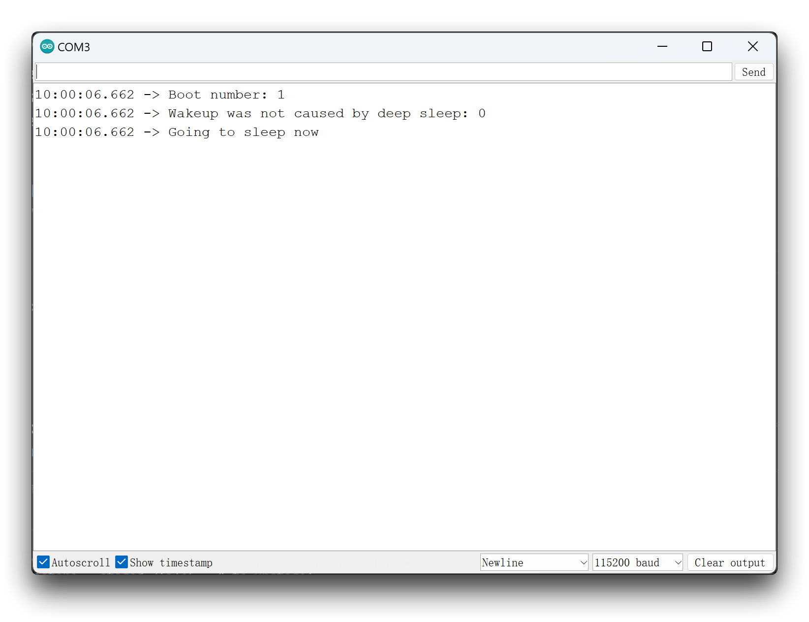
After entering deep sleep mode, the XIAO's port will disappear and you'll need to wake it up to see its port number again!
In the program, we are using a D1 low level to wake up. This means that we can connect a button to pin D1 and the XIAO will wake up when we press the button.
The XIAO ESP32-C3 supports GPIO wake-up and timer wake-up, and the pins that support wake-up are D0~D3.
Troubleshooting
Q1: My Arduino IDE is stuck when uploading code to the board
You can first try to reset the board by clicking the RESET BUTTON once while the board is connected to your PC. If that does not work, hold the BOOT BUTTON, connect the board to your PC while holding the BOOT button, and then release it to enter bootloader mode.
Q2: My board is not showing up as a serial device on Arduino IDE
Follow the same answer as for Q1 above.
Q3: I want to reflash the bootloader with factory firmware
You can simply connect the board to a PC via USB Type-C and reflash the bootloader with factory firmware by using ESP RF Test Tool.
-
Step 1. Hold on the BOOT BUTTON and connect XIAO ESP32C3 to the PC to enter bootloader mode
-
Step 2. After it is connected, release the BOOT BUTTON
-
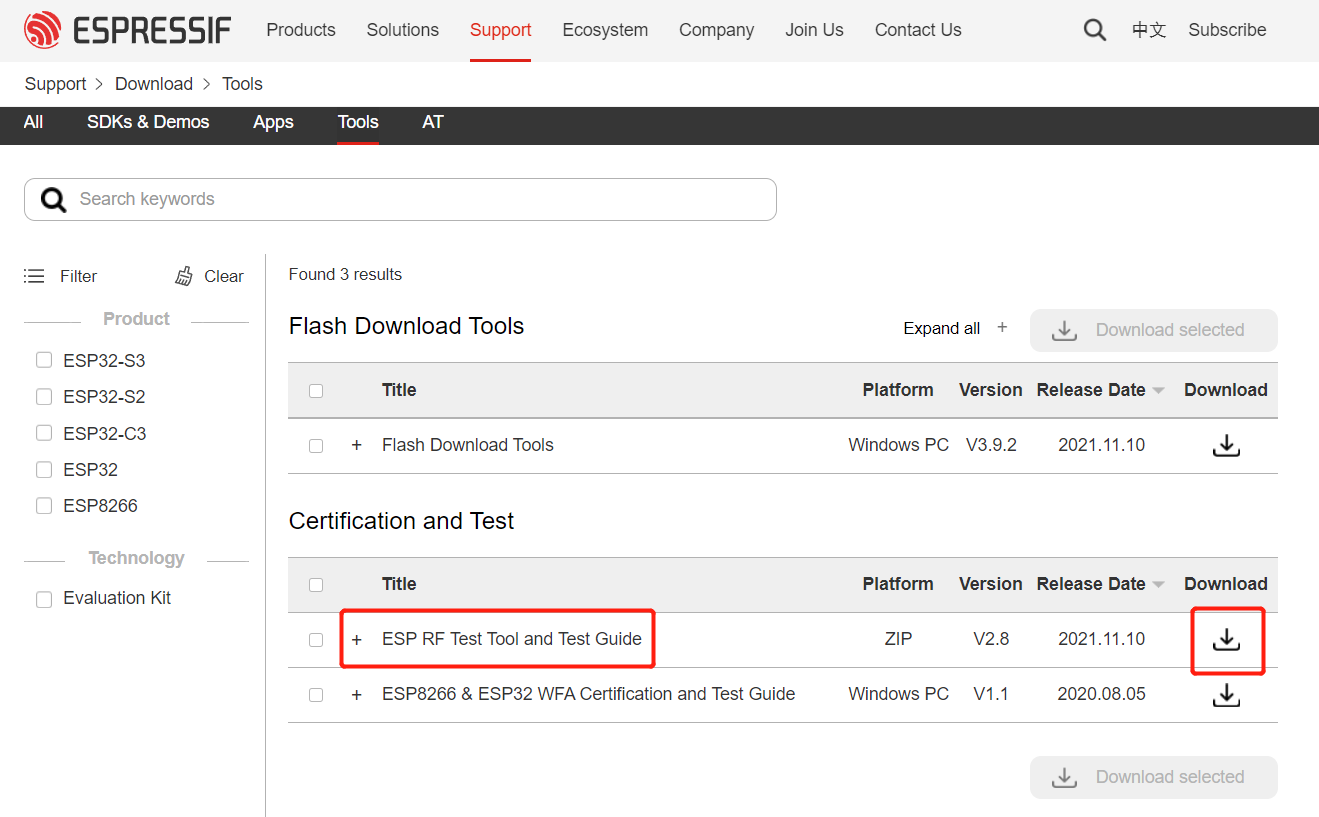
Step 3. Visit this page and download ESP RF Test Tool and Test Guide
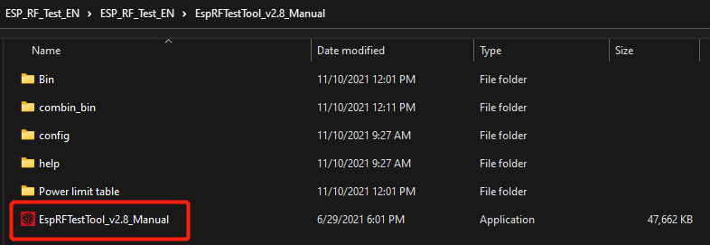
- Step 4. Extract the .zip, navigate to
ESP_RF_Test_EN\ESP_RF_Test_EN\EspRFTestTool_v2.8_Manualand open EspRFTestTool_v2.8_Manual.exe
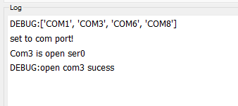
- Step 5. Select ESP32C3 as the ChipType, your COM port, 115200 as the BaudRate and click open
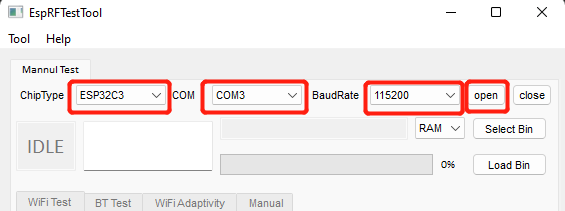
You will see the following output
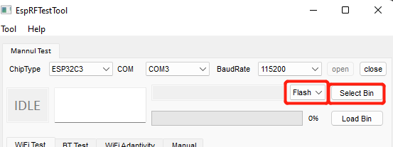
- Step 6. Select Flash and click Select Bin
-
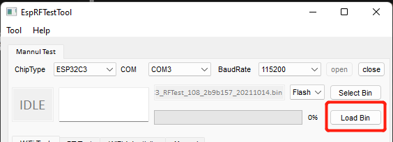
Step 7. Download the factory firmware of XIAO ESP32C3 and select it.
-
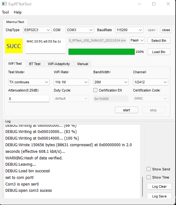
Step 8. Finally click Load Bin
You will see the following output when flashing is successful
MicroPython GitHub Repository
Resources
Hardware Design
- 📄[Datasheet] Espressif ESP32-C3 Datasheet
- 📄[Schematic] XIAO ESP32-C3 Schematic
- 🗃️[PCB Design Files]
- 🗃️[PCB Design Libraries]
- 📄[Pinout Diagram] XIAO ESP32-C3 Pinout Sheet
Mechanical
- 📄[2D Dimensions] XIAO ESP32-C3 Dimension in DXF
- 🗃️[2D Dimensions] XIAO ESP32-C3 Bottom Pad Data
- 📄[3D Model] XIAO ESP32-C3 3D Model
Software & Tools
- 🗃️[Factory Firmware] XIAO ESP32-C3 Factory Firmware
- 🔗[MicroPython Library] XIAO ESP32-C3 MicroPython Library
- 🔗[Platform IO] PlatformIO for Seeed Studio XIAO ESP32-C3
Others
- 🔗[Wiki] First Look at the Seeed Studio XIAO ESP32-C3
- A great intro to the XIAO ESP32C3, covering key features and basic usage.
- 📄[Document] Report of XIAO ESP32-C3 Low Power Consumption
Course Resources
Tech Support & Product Discussion
Thank you for choosing our products! We are here to provide you with different support to ensure that your experience with our products is as smooth as possible. We offer several communication channels to cater to different preferences and needs.