Grove - Sound Sensor

Grove - Sound Sensor can detect the sound intensity of the environment. The main component of the module is a simple microphone, which is based on the L358 amplifier and an electret microphone. This module's output is analog and can be easily sampled and tested by a Seeeduino.

Features
- Easy to use
- Provides analog output signal
- Easily integrates with Logic modules on the input side of Grove circuits
This sound sensor is used to detect whether there's sound surround or not, please don't use the module to collect sound signal. For example, you can use it to make a sound control lamp, but not as a recording device.
Specifications
| Item | Value |
|---|---|
| Operating Voltage Range | 5 V |
| Operating Current(Vcc=5V) | 4~5 mA |
| Voltage Gain(V=6V, f=1kHz) | 26 dB |
| Microphone sensitivity(1kHz) | -60~-56dBV/Pa |
| Microphone Impedance | 2.2k Ohm |
| Microphone Frequency | 16-20 kHz |
| Microphone S/N Radio | 54 dB |
More details about Grove modules please refer to Grove System
Platforms Supported
| Arduino | Raspberry Pi | |||
|---|---|---|---|---|
The platforms mentioned above as supported is/are an indication of the module's software or theoritical compatibility. We only provide software library or code examples for Arduino platform in most cases. It is not possible to provide software library / demo code for all possible MCU platforms. Hence, users have to write their own software library.
Getting Started
If this is the first time you work with Arduino, we firmly recommend you to see Getting Started with Arduino before the start.
Play With Arduino
Hardware
- Step 1. Prepare the below stuffs:
| Seeeduino V4.2 | Base Shield | Grove-Sound Sensor |
|---|---|---|
 |  | |
| Get One Now | Get One Now | Get One Now |
- Step 2. Connect Grove-Sound Sensor to port A0 of Grove-Base Shield.
- Step 3. Plug Grove - Base Shield into Seeeduino.
- Step 4. Connect Seeeduino to PC via a USB cable.

If we don't have Grove Base Shield, We also can directly connect Grove-Sound Sensor to Seeeduino as below.
| Seeeduino | Grove-Sound Sensor |
|---|---|
| 5V | Red |
| GND | Black |
| A1 | White |
| A0 | Yellow |
Software
- Step 1. Please copy below code to Arduio IDE and upload to arduino. If you do not know how to upload the code, please check how to upload code.
// test code for Grove - Sound Sensor
// loovee @ 2016-8-30

const int pinAdc = A0;

void setup()
{
    Serial.begin(115200);
    //Serial.println("Grove - Sound Sensor Test...");
}

void loop()
{
    long sum = 0;
    for(int i=0; i<32; i++)
    {
        sum += analogRead(pinAdc);
    }

    sum >>= 5;

    Serial.println(sum);
    delay(10);
}
- Step 2. Click on Serial > Plotter to get the changing curve of the sensor. Please make a noise to view the change of the value.

Play with Codecraft
Hardware
Step 1. Connect a Grove - Sound Sensor to port A0 of a Base Shield.
Step 2. Plug the Base Shield to your Seeeduino/Arduino.
Step 3. Link Seeeduino/Arduino to your PC via an USB cable.
Software
Step 1. Open Codecraft, add Arduino support, and drag a main procedure to working area.
If this is your first time using Codecraft, see also Guide for Codecraft using Arduino.
Step 2. Drag blocks as picture below or open the cdc file which can be downloaded at the end of this page.

Upload the program to your Arduino/Seeeduino.
When the code finishes uploaded, you will see the sound value displayed in the Serial Monitor.
Play With Raspberry Pi (With Grove Base Hat for Raspberry Pi)
Hardware
- Step 1. Things used in this project:
| Raspberry pi | Grove Base Hat for RasPi | Grove - Sound Sensor |
|---|---|---|
 | 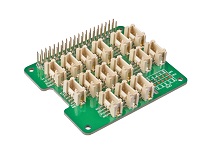 | |
| Get ONE Now | Get ONE Now | Get ONE Now |
- Step 2. Plug the Grove Base Hat into Raspberry.
- Step 3. Connect the Grove - Sound Sensor to port A0 of the Base Hat.
- Step 4. Connect the Raspberry Pi to PC through USB cable.

For step 3 you are able to connect the sound sensor to any Analog Port but make sure you change the command with the corresponding port number.
Software
If you are using Raspberry Pi with Raspberrypi OS >= Bullseye, you have to use this command line only with Python3.
- Step 1. Follow Setting Software to configure the development environment.
- Step 2. Download the source file by cloning the grove.py library.
cd ~
git clone https://github.com/Seeed-Studio/grove.py
- Step 3. Excute below commands to run the code.
cd grove.py/grove
python3 grove_sound_sensor.py 0
Following is the grove_sound_sensor.py code.
import math
import sys
import time
from grove.adc import ADC


class GroveSoundSensor:

    def __init__(self, channel):
        self.channel = channel
        self.adc = ADC()

    @property
    def sound(self):
        value = self.adc.read(self.channel)
        return value

Grove = GroveSoundSensor


def main():
    if len(sys.argv) < 2:
        print('Usage: {} adc_channel'.format(sys.argv[0]))
        sys.exit(1)

    sensor = GroveSoundSensor(int(sys.argv[1]))

    print('Detecting sound...')
    while True:
        print('Sound value: {0}'.format(sensor.sound))
        time.sleep(.3)

if __name__ == '__main__':
    main()
If everything goes well, you will be able to see the following result
pi@raspberrypi:~/grove.py/grove $ python3 grove_sound_sensor.py 0
Detecting sound...
Sound value: 499
Sound value: 525
Sound value: 529
Sound value: 493
Sound value: 457
Sound value: 457
Sound value: 503
Sound value: 537
Sound value: 606
Sound value: 614
Sound value: 661
^CTraceback (most recent call last):
  File "grove_sound_sensor.py", line 67, in <module>
    main()
  File "grove_sound_sensor.py", line 64, in main
    time.sleep(.3)
KeyboardInterrupt
You can quit this program by simply press ++ctrl+c++.
You may have noticed that for the analog port, the silkscreen pin number is something like A1, A0, however in the command we use parameter 0 and 1, just the same as digital port. So please make sure you plug the module into the correct port, otherwise there may be pin conflicts.
Play With Raspberry Pi (with GrovePi_Plus)
Hardware
- Step 1. Prepare the below stuffs:
| Raspberry pi | GrovePi_Plus | Grove-Sound Sensor | Grove-Blue LED |
|---|---|---|---|
| 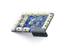 |  |  |
| Get One Now | Get One Now | Get One Now | Get One Now |
-
Step 2. Plug the GrovePi_Plus into Raspberry.
-
Step 3. Connect Grove-Sound Sensor to A0 port of GrovePi_Plus , and connect Grove-Blue LED to D5 port of GrovePi_Plus
-
Step 4. Connect the Raspberry to PC through USB cable.

Software
-
Step 1. Follow Setting Software to configure the development environment.
-
Step 2. Follow Updating the Firmware to update the newest firmware of GrovePi.
If you are using Raspberry Pi with Raspberrypi OS >= Bullseye, you have to use this command line only with Python3.
In this wiki we use the path ~/GrovePi/ instead of /home/pi/Desktop/GrovePi, you need to make sure Step 2 and Step 3 use the same path.
We firmly suggest you to update the firmware, or for some sensors you may get errors.
- Step 3. Git clone the Github repository.
cd ~
git clone https://github.com/DexterInd/GrovePi.git
- Step 4. Navigate to the demos' directory:
cd yourpath/GrovePi/Software/Python/
Here is the grove_sound_sensor.py code.
#!/usr/bin/env python
#
# GrovePi Example for using the Grove Sound Sensor and the Grove LED
#
# The GrovePi connects the Raspberry Pi and Grove sensors.  You can learn more about GrovePi here:  http://www.dexterindustries.com/GrovePi
#
# Modules:
#  https://www.seeedstudio.com/wiki/Grove_-_Sound_Sensor
#  https://www.seeedstudio.com/wiki/Grove_-_LED_Socket_Kit
#
# Have a question about this example?  Ask on the forums here:  http://forum.dexterindustries.com/c/grovepi
#
'''
## License
The MIT License (MIT)
GrovePi for the Raspberry Pi: an open source platform for connecting Grove Sensors to the Raspberry Pi.
Copyright (C) 2017  Dexter Industries
Permission is hereby granted, free of charge, to any person obtaining a copy
of this software and associated documentation files (the "Software"), to deal
in the Software without restriction, including without limitation the rights
to use, copy, modify, merge, publish, distribute, sublicense, and/or sell
copies of the Software, and to permit persons to whom the Software is
furnished to do so, subject to the following conditions:
The above copyright notice and this permission notice shall be included in
all copies or substantial portions of the Software.
THE SOFTWARE IS PROVIDED "AS IS", WITHOUT WARRANTY OF ANY KIND, EXPRESS OR
IMPLIED, INCLUDING BUT NOT LIMITED TO THE WARRANTIES OF MERCHANTABILITY,
FITNESS FOR A PARTICULAR PURPOSE AND NONINFRINGEMENT. IN NO EVENT SHALL THE
AUTHORS OR COPYRIGHT HOLDERS BE LIABLE FOR ANY CLAIM, DAMAGES OR OTHER
LIABILITY, WHETHER IN AN ACTION OF CONTRACT, TORT OR OTHERWISE, ARISING FROM,
OUT OF OR IN CONNECTION WITH THE SOFTWARE OR THE USE OR OTHER DEALINGS IN
THE SOFTWARE.
'''

import time
import grovepi

# Connect the Grove Sound Sensor to analog port A0
# SIG,NC,VCC,GND
sound_sensor = 0

# Connect the Grove LED to digital port D5
# SIG,NC,VCC,GND
led = 5

grovepi.pinMode(sound_sensor,"INPUT")
grovepi.pinMode(led,"OUTPUT")

# The threshold to turn the led on 400.00 * 5 / 1024 = 1.95v
threshold_value = 400

while True:
    try:
        # Read the sound level
        sensor_value = grovepi.analogRead(sound_sensor)

        # If loud, illuminate LED, otherwise dim
        if sensor_value > threshold_value:
            grovepi.digitalWrite(led,1)
        else:
            grovepi.digitalWrite(led,0)

        print("sensor_value = %d" %sensor_value)
        time.sleep(.5)

    except IOError:
        print ("Error")
- Step 5. Run the demo.
sudo python3 grove_sound_sensor.py
Schematic Online Viewer
Resources
- [Eagle]Schematic and PCB in Eagle format
- [PDF]Schematic in PDF format
- [PDF]PCB in PDF format
- [Datasheet]LM358.PDF
- [Codecraft]CDC File
Projects
Create a multi-tasking IoT Wi-Fi sensor: This tutorial showcases how to make an internet-connected sensor, while leveraging unique multi-tasking features of Energia & TI LaunchPad.
LED Sound Meter using Wio-Link and Node-Red: SeeedStudio Grove sound sensor and LED strip attached to Wio-Link being driven by a Node-Red flow.
Sound sensor Grove module:
Upgradable to Industrial Sensors
With the SenseCAP S2110 controller and S2100 data logger, you can easily turn the Grove into a LoRaWAN® sensor. Seeed not only helps you with prototyping but also offers you the possibility to expand your project with the SenseCAP series of robust industrial sensors.
The IP66 housing, Bluetooth configuration, compatibility with the global LoRaWAN® network, built-in 19 Ah battery, and powerful support from APP make the SenseCAP S210x the best choice for industrial applications. The series includes sensors for soil moisture, air temperature and humidity, light intensity, CO2, EC, and an 8-in-1 weather station. Try the latest SenseCAP S210x for your next successful industrial project.

Tech Support & Product Discussion
Thank you for choosing our products! We are here to provide you with different support to ensure that your experience with our products is as smooth as possible. We offer several communication channels to cater to different preferences and needs.