Seeed Studio XIAO nRF52840(Sense)引脚复用
Seeed Studio XIAO nRF52840(Sense)拥有丰富的接口。它有 11 个数字 I/O 可用作 PWM 引脚,以及 6 个模拟输入 可用作 ADC 引脚。它支持三种常见的串行通信接口:UART、I2C 和 SPI。本 Wiki 将帮助你了解这些接口,并在你的下一个项目中加以实现!
这里的基础功能在两个 Seeed Studio XIAO nRF52840 Arduino 库上都能很好地工作。
硬件概览
- XIAO nRF52840
- XIAO nRF52840 Plus
- XIAO nRF52840 Sense
- XIAO nRF52840 Sense Plus
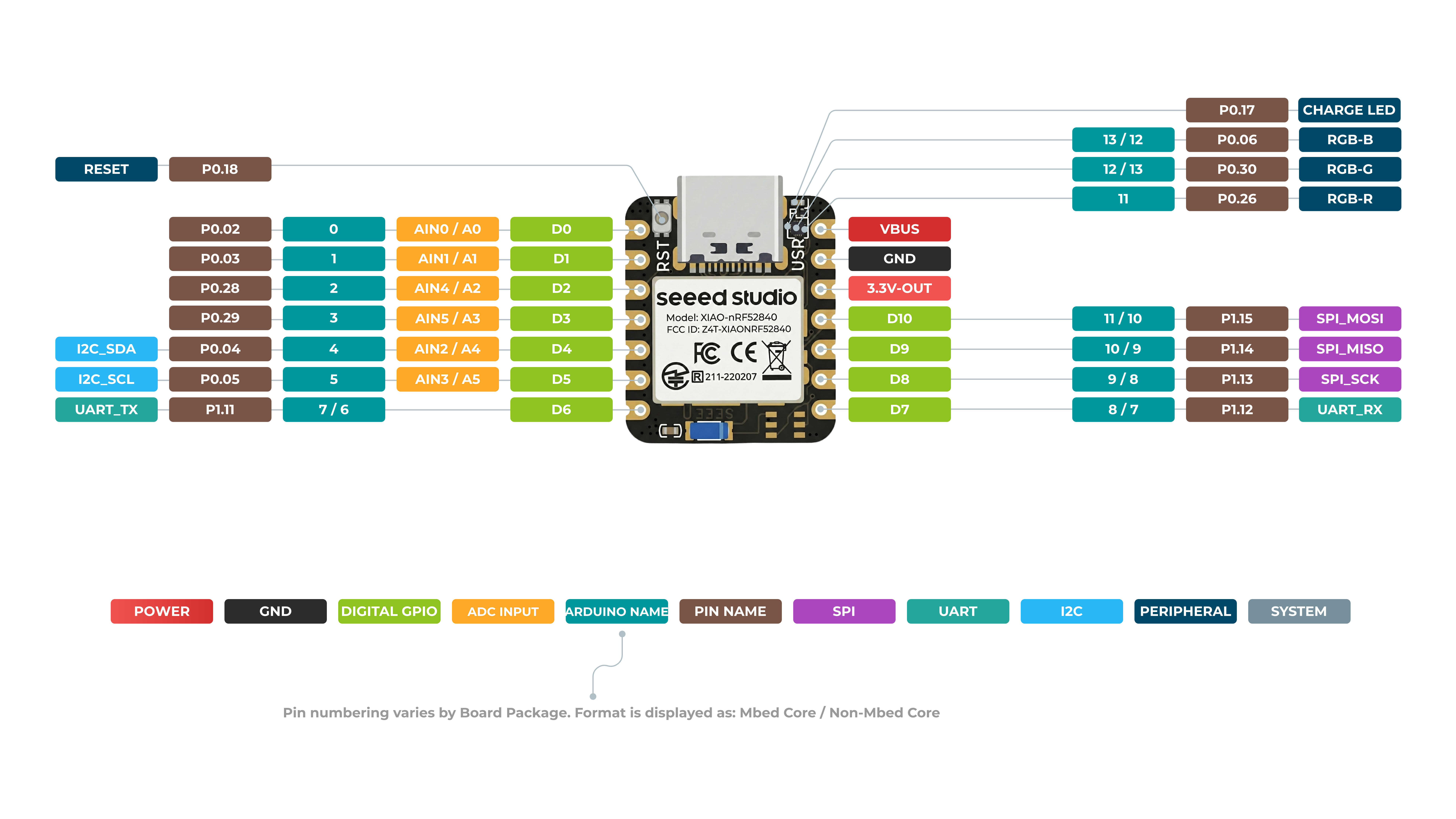
XIAO nRF52840 正面
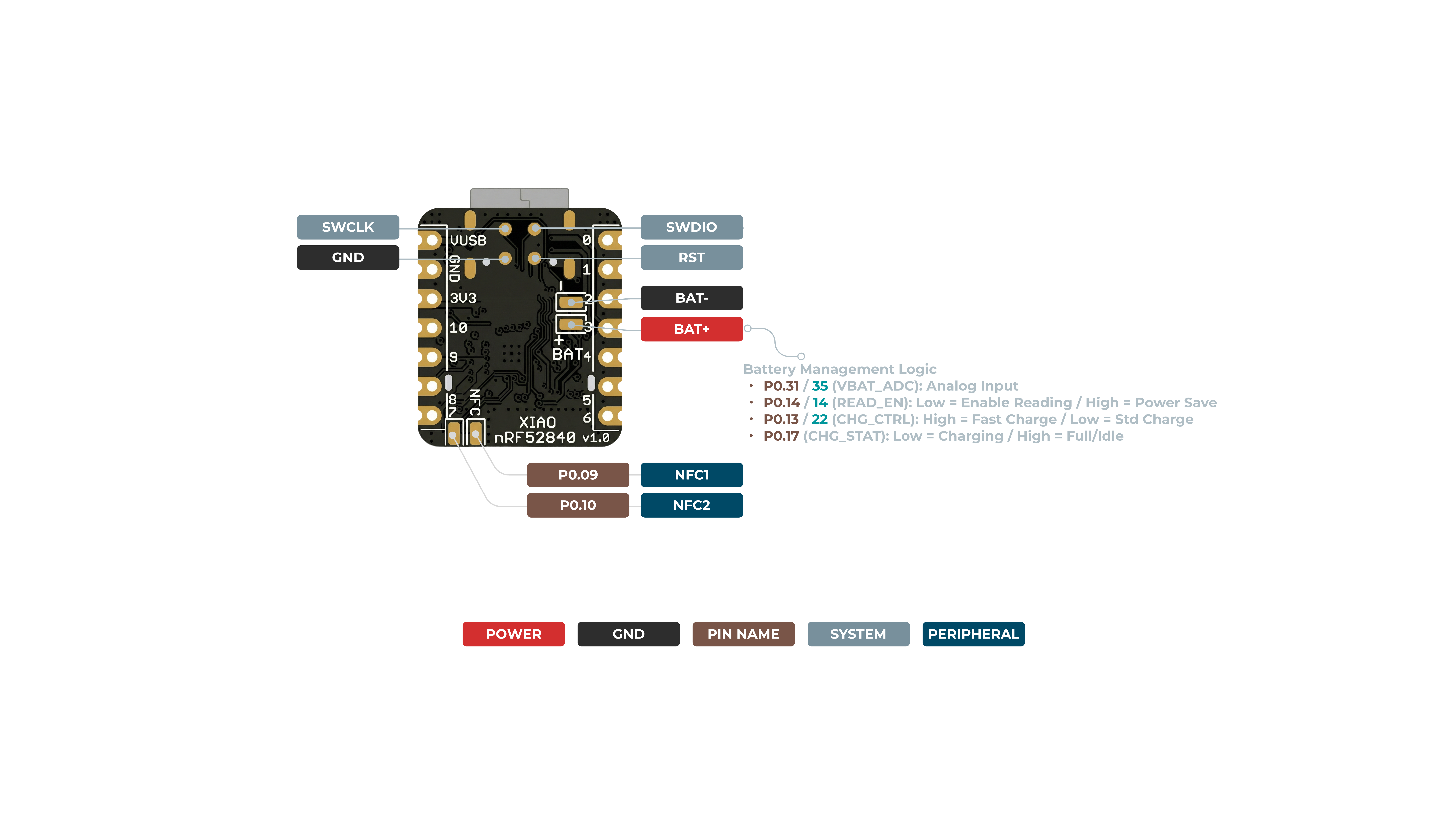
XIAO nRF52840 背面
引脚映射
| XIAO 引脚 | 功能 | 芯片引脚 | 描述 | Arduino 名称 |
|---|---|---|---|---|
| 5V | VBUS | 电源输入/输出 | ||
| GND | ||||
| 3V3 | 3V3_OUT | 电源输出 | ||
| D0 | 模拟 | P0.02 | GPIO,AIN0 | 0 |
| D1 | 模拟 | P0.03 | GPIO,AIN1 | 1 |
| D2 | 模拟 | P0.28 | GPIO,AIN4 | 2 |
| D3 | 模拟 | P0.29 | GPIO,AIN5 | 3 |
| D4 | 模拟,SDA | P0.04 | GPIO,I2C 数据,AIN2 | 4 |
| D5 | 模拟,SCL | P0.05 | GPIO,I2C 时钟,AIN3 | 5 |
| D6 | TX | P1.11 | GPIO,UART 发送 | 7/6 |
| D7 | RX | P1.12 | GPIO,UART 接收 | 8/7 |
| D8 | SPI_SCK | P1.13 | GPIO,SPI 时钟 | 9/8 |
| D9 | SPI_MISO | P1.14 | GPIO,SPI 数据 | 10/9 |
| D10 | SPI_MOSI | P1.15 | GPIO,SPI 数据 | 11/10 |
| NFC1 | P0.09 | NFC | ||
| NFC2 | P0.10 | NFC | ||
| Reset | P0.18 | 复位 | ||
| ADC_BAT | READ_BAT_ENABLE | P0.14 | 电池电压读取使能控制 | |
| RF Switch Port Select | P2.05 | 切换板载天线 | ||
| RF Switch Power | P2.03 | 电源 | ||
| CHARGE_LED | P0.17 | CHG-LED_Red | ||
| USER_LED_R | P0.26 | 用户控制的红色 RGB LED 引脚 | 11 | |
| USER_LED_B | P0.06 | 用户控制的蓝色 RGB LED 引脚 | 13/12 | |
| USER_LED_G | P0.30 | 用户控制的绿色 RGB LED 引脚 | 12/13 |
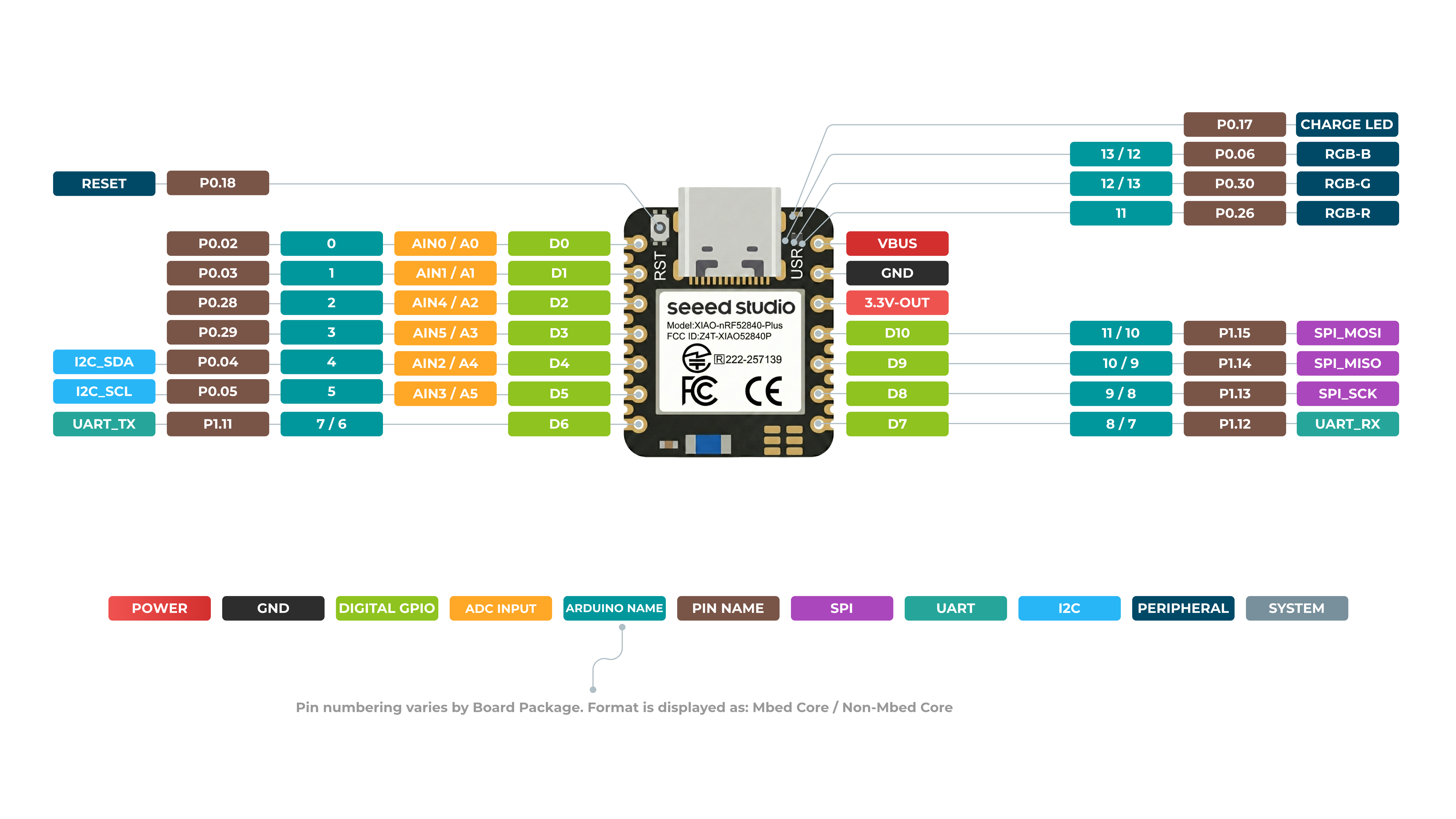
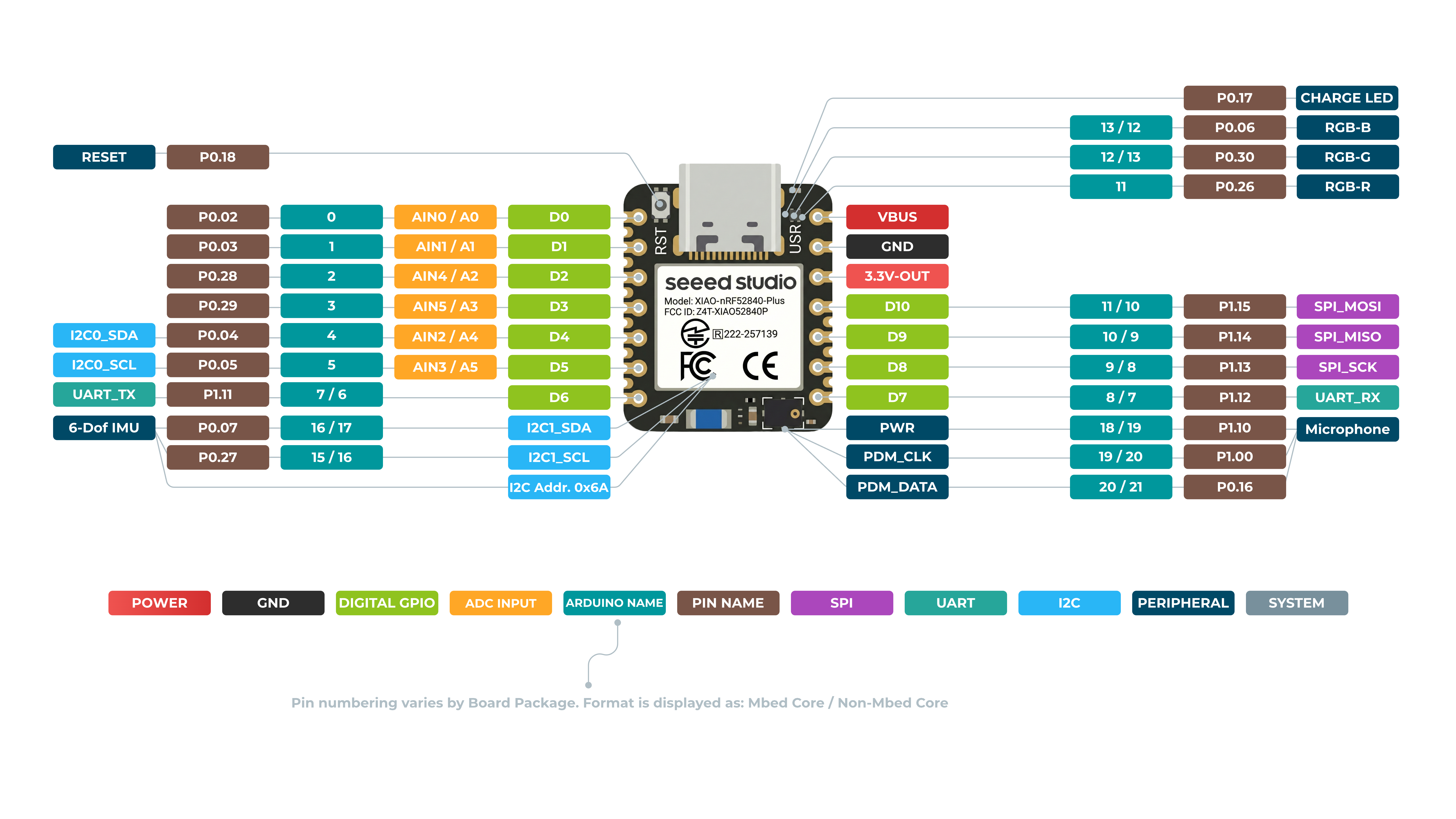
XIAO nRF52840 Plus 正面
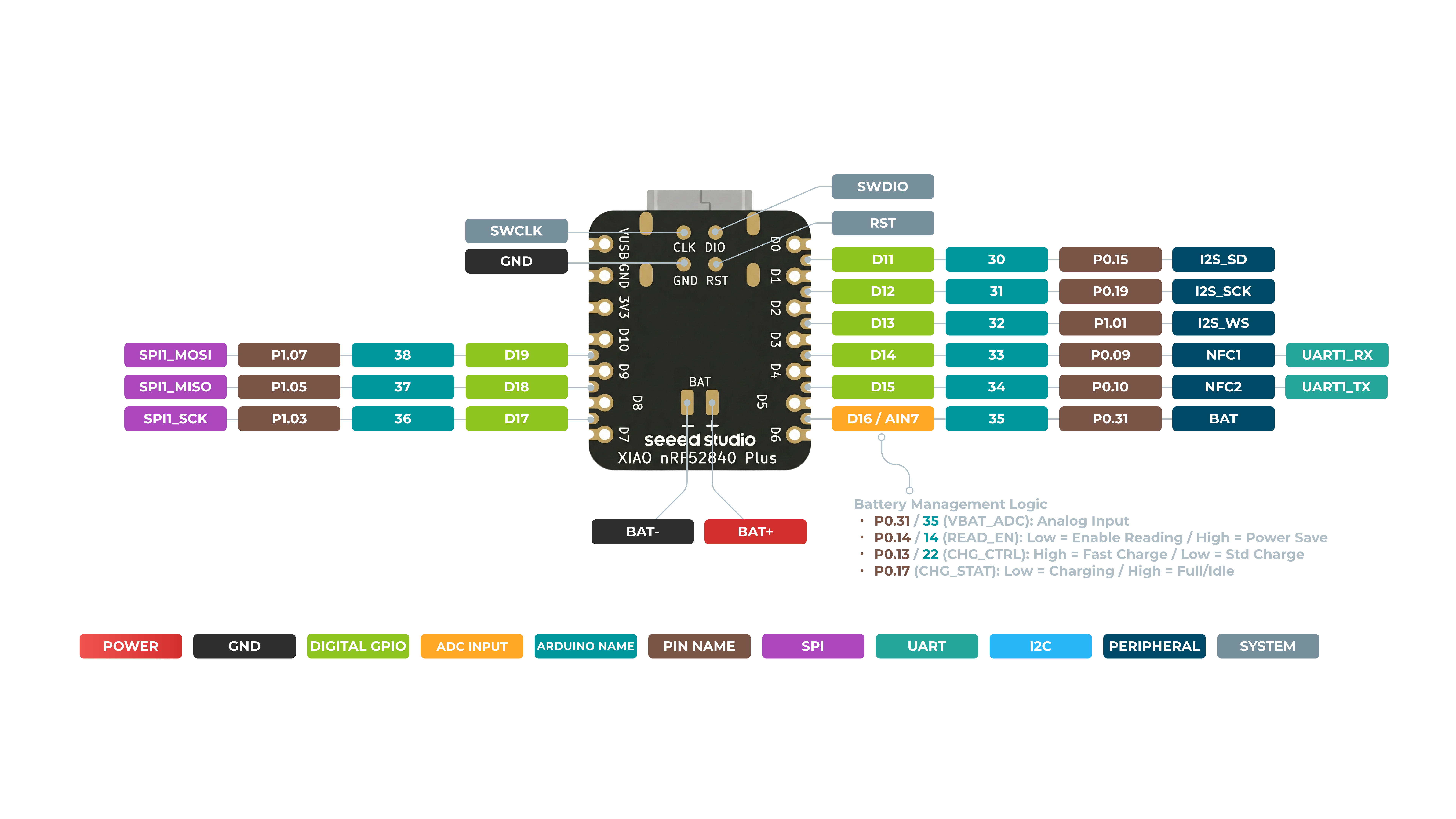
XIAO nRF52840 Plus 背面

引脚映射
| XIAO 引脚 | 功能 | 芯片引脚 | 复用功能 | 描述 | Arduino 名称 |
|---|---|---|---|---|---|
| 5V | VBUS | 电源输入/输出 | |||
| GND | |||||
| 3V3 | 3V3_OUT | 电源输出 | |||
| D0 | 模拟 | P0.02 | GPIO,ADC | 0 | |
| D1 | 模拟 | P0.03 | GPIO,ADC | 1 | |
| D2 | 模拟 | P0.28 | GPIO,ADC | 2 | |
| D3 | 模拟 | P0.29 | GPIO,ADC | 3 | |
| D4 | 模拟,SDA | P0.04 | GPIO,I2C 数据,ADC | 4 | |
| D5 | 模拟,SCL | P0.05 | GPIO,I2C 时钟,ADC | 5 | |
| D6 | TX | P1.11 | GPIO,UART 发送 | 7/6 | |
| D7 | RX | P1.12 | GPIO,UART 接收 | 8/7 | |
| D8 | SPI_SCK | P1.13 | GPIO,SPI 时钟 | 9/8 | |
| D9 | SPI_MISO | P1.14 | GPIO,SPI 数据 | 10/9 | |
| D10 | SPI_MOSI | P1.15 | GPIO,SPI 数据 | 11/10 | |
| D11 | I2S_SD | P0.15 | GPIO,I2S,ADC | ||
| D12 | I2S_SCK | P0.19 | GPIO,I2S,ADC | ||
| D13 | I2S_WS | P1.01 | GPIO,I2S,ADC | ||
| D14 | RX1 | P0.09 | NFC1 | GPIO,UART 接收,ADC | |
| D15 | TX1 | P0.10 | NFC2 | GPIO,UART 发送,ADC | |
| D16 | AIN7_BAT | P0.31 | 电池电压 ADC 读取引脚 | ||
| D17 | SCK1 | P1.03 | GPIO,SPI | ||
| D18 | MISO1 | P1.05 | GPIO,SPI | ||
| D19 | MOSI1 | P1.07 | GPIO,SPI | ||
| ADC_BAT | READ_BAT_ENABLE | P0.14 | 电池电压读取使能控制 | ||
| Reset | P0.18 | 复位 | |||
| RF Switch Port Select | P2.05 | 切换板载天线 | |||
| RF Switch Power | P2.03 | 电源 | |||
| CHARGE_LED | P0.17 | CHG-LED_Red | |||
| USER_LED_R | P0.26 | 用户控制的红色 RGB LED 引脚 | 11 | ||
| USER_LED_B | P0.06 | 用户控制的蓝色 RGB LED 引脚 | 13/12 | ||
| USER_LED_G | P0.30 | 用户控制的绿色 RGB LED 引脚 | 12/13 |
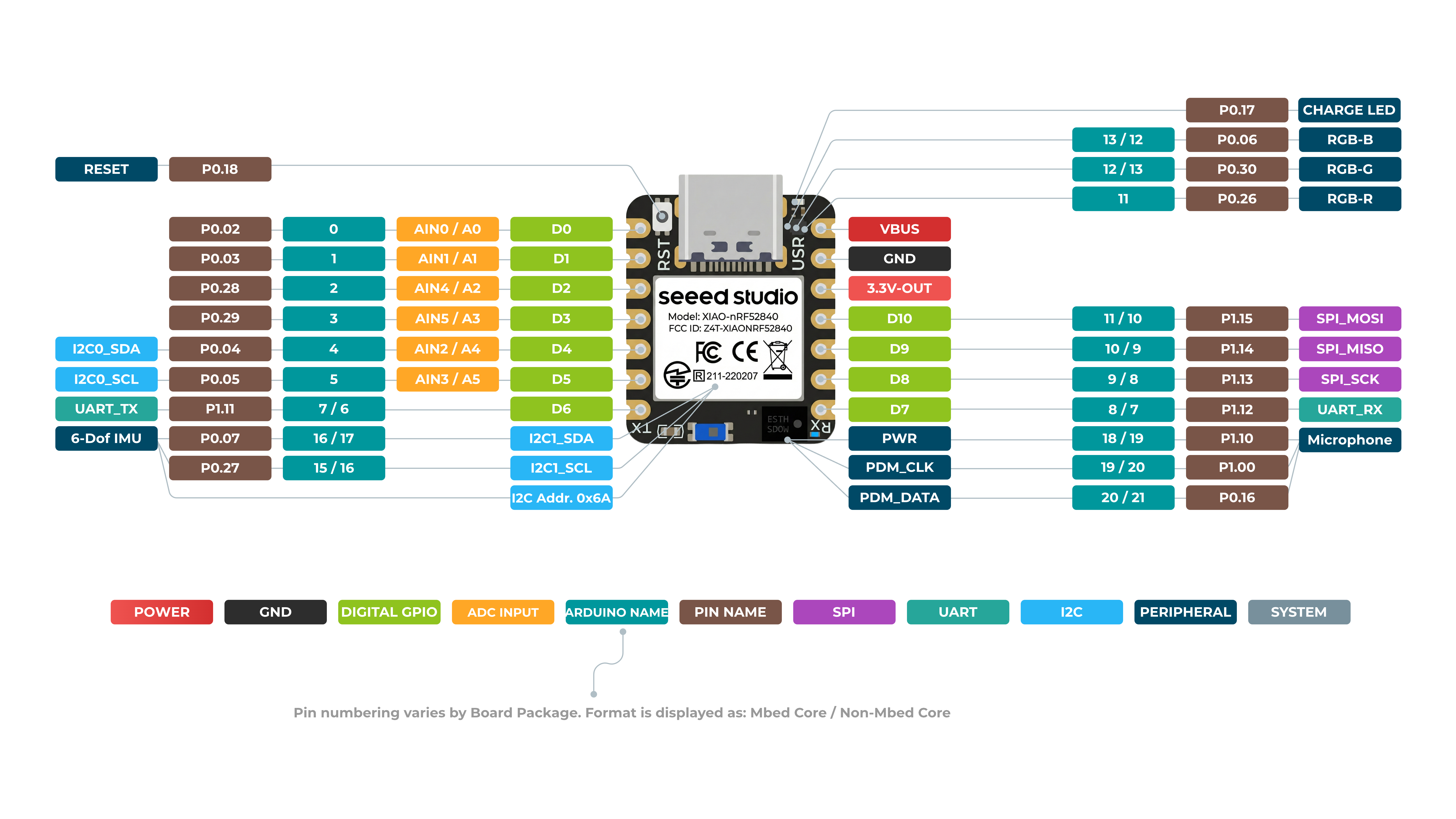
XIAO nRF52840 Sense 正面
XIAO nRF52840 Sense 背面

引脚映射
| XIAO 引脚 | 功能 | 芯片引脚 | 描述 | Arduino 名称 |
|---|---|---|---|---|
| 5V | VBUS | 电源输入/输出 | ||
| GND | ||||
| 3V3 | 3V3_OUT | 电源输出 | ||
| D0 | 模拟 | P0.02 | GPIO,AIN0 | 0 |
| D1 | 模拟 | P0.03 | GPIO,AIN1 | 1 |
| D2 | 模拟 | P0.28 | GPIO,AIN4 | 2 |
| D3 | 模拟 | P0.29 | GPIO,AIN5 | 3 |
| D4 | 模拟,SDA | P0.04 | GPIO,I2C 数据,AIN2 | 4 |
| D5 | 模拟,SCL | P0.05 | GPIO,I2C 时钟,AIN3 | 5 |
| D6 | TX | P1.11 | GPIO,UART 发送 | 7/6 |
| D7 | RX | P1.12 | GPIO,UART 接收 | 8/7 |
| D8 | SPI_SCK | P1.13 | GPIO,SPI 时钟 | 9/8 |
| D9 | SPI_MISO | P1.14 | GPIO,SPI 数据 | 10/9 |
| D10 | SPI_MOSI | P1.15 | GPIO,SPI 数据 | 11/10 |
| NFC1 | P0.09 | NFC | ||
| NFC2 | P0.10 | NFC | ||
| Reset | P0.18 | 复位 | ||
| ADC_BAT | READ_BAT_ENABLE | P0.14 | 电池电压读取使能控制 | |
| 6 DOF IMU_PWR | P1.08 | 6D 模组电源开关 | ||
| 6 DOF IMU__INT1 | P0.11 | 6D 模组中断信号引脚 | ||
| PDM Microphone_DATA | P0.16 | PDM 音频数据输入引脚 | ||
| PDM Microphone_CLK | P1.00 | PDM 音频时钟输出引脚 | ||
| RF Switch Port Select | P2.05 | 切换板载天线 | ||
| RF Switch Power | P2.03 | 电源 | ||
| CHARGE_LED | P0.17 | CHG-LED_Red | ||
| USER_LED_R | P0.26 | 用户控制的红色 RGB LED 引脚 | 11 | |
| USER_LED_B | P0.06 | 用户控制的蓝色 RGB LED 引脚 | 13/12 | |
| USER_LED_G | P0.30 | 用户控制的绿色 RGB LED 引脚 | 12/13 |
XIAO nRF52840 Sense Plus 正面
XIAO nRF52840 Sense Plus 背面
引脚映射
| XIAO 引脚 | 功能 | 芯片引脚 | 复用功能 | 描述 | Arduino 名称 |
|---|---|---|---|---|---|
| 5V | VBUS | 电源输入/输出 | |||
| GND | |||||
| 3V3 | 3V3_OUT | 电源输出 | |||
| D0 | 模拟 | P0.02 | GPIO,ADC | 0 | |
| D1 | 模拟 | P0.03 | GPIO,ADC | 1 | |
| D2 | 模拟 | P0.28 | GPIO,ADC | 2 | |
| D3 | 模拟 | P0.29 | GPIO,ADC | 3 | |
| D4 | 模拟,SDA | P0.04 | GPIO,I2C 数据,ADC | 4 | |
| D5 | 模拟,SCL | P0.05 | GPIO,I2C 时钟,ADC | 5 | |
| D6 | TX | P1.11 | GPIO,UART 发送 | 7/6 | |
| D7 | RX | P1.12 | GPIO,UART 接收 | 8/7 | |
| D8 | SPI_SCK | P1.13 | GPIO,SPI 时钟 | 9/8 | |
| D9 | SPI_MISO | P1.14 | GPIO,SPI 数据 | 10/9 | |
| D10 | SPI_MOSI | P1.15 | GPIO,SPI 数据 | 11/10 | |
| D11 | I2S_SD | P0.15 | GPIO,I2S,ADC | ||
| D12 | I2S_SCK | P0.19 | GPIO,I2S,ADC | ||
| D13 | I2S_WS | P1.01 | GPIO,I2S,ADC | ||
| D14 | RX1 | P0.09 | NFC1 | GPIO,UART 接收,ADC | |
| D15 | TX1 | P0.10 | NFC2 | GPIO,UART 发送,ADC | |
| D16 | AIN7_BAT | P0.31 | 电池电压 ADC 读取引脚 | ||
| D17 | SCK1 | P1.03 | GPIO,SPI | ||
| D18 | MISO1 | P1.05 | GPIO,SPI | ||
| D19 | MOSI1 | P1.07 | GPIO,SPI | ||
| ADC_BAT | READ_BAT_ENABLE | P0.14 | 电池电压读取使能控制 | ||
| 6 DOF IMU_PWR | P1.08 | 6D 模组电源开关 | |||
| 6 DOF IMU__INT1 | P0.11 | 6D 模组中断信号引脚 | |||
| PDM Microphone_DATA | P0.16 | PDM 音频数据输入引脚 | |||
| PDM Microphone_CLK | P1.00 | PDM 音频时钟输出引脚 | |||
| Reset | P0.18 | 复位 | |||
| RF Switch Port Select | P2.05 | 切换板载天线 | |||
| RF Switch Power | P2.03 | 电源 | |||
| CHARGE_LED | P0.17 | CHG-LED_Red | |||
| USER_LED_R | P0.26 | 用户控制的红色 RGB LED 引脚 | 11 | ||
| USER_LED_B | P0.06 | 用户控制的蓝色 RGB LED 引脚 | 13/12 | ||
| USER_LED_G | P0.30 | 用户控制的绿色 RGB LED 引脚 | 12/13 |
数字
将一个按键连接到引脚 D6,将一个 LED 连接到引脚 D10。然后上传以下代码,通过按键控制 LED 的开/关。
const int buttonPin = 6;     // pushbutton connected to digital pin 6
const int ledPin =  10;      // LED connected to digital pin 10

int buttonState = 0;         // variable for reading the pushbutton status

void setup() {
  // initialize the LED pin as an output:
  pinMode(ledPin, OUTPUT);
  // initialize the pushbutton pin as an input:
  pinMode(buttonPin, INPUT);
}

void loop() {
  // read the state of the pushbutton value:
  buttonState = digitalRead(buttonPin);

  // check if the pushbutton is pressed. If it is, the buttonState is HIGH:
  if (buttonState == HIGH) {
    // turn LED off:
    digitalWrite(ledPin, HIGH);
  } else {
    // turn LED on:
    digitalWrite(ledPin, LOW);
  }
}
数字作为 PWM
将一个 LED 连接到引脚 D10。然后上传以下代码,观察 LED 逐渐变暗。
int ledPin = 10;    // LED connected to digital pin 10

void setup() {

}

void loop() {
  // fade in from min to max in increments of 5 points:
  for (int fadeValue = 0 ; fadeValue <= 255; fadeValue += 5) {
    // sets the value (range from 0 to 255):
    analogWrite(ledPin, fadeValue);
    // wait for 30 milliseconds to see the dimming effect
    delay(30);
  }

  // fade out from max to min in increments of 5 points:
  for (int fadeValue = 255 ; fadeValue >= 0; fadeValue -= 5) {
    // sets the value (range from 0 to 255):
    analogWrite(ledPin, fadeValue);
    // wait for 30 milliseconds to see the dimming effect
    delay(30);
  }
}
模拟
将电位器连接到引脚 A5,将 LED 连接到引脚 D10。然后上传以下代码,通过旋转电位器旋钮来控制 LED 的闪烁间隔。
const int sensorPin = 5;
const int ledPin =  10;
void setup() {
  // declare the ledPin as an OUTPUT:
  pinMode(sensorPin, INPUT);
  pinMode(ledPin, OUTPUT);
}

void loop() {
  // read the value from the sensor:
  int sensorValue = analogRead(sensorPin);
  // turn the ledPin on
  digitalWrite(ledPin, HIGH);
  // stop the program for <sensorValue> milliseconds:
  delay(sensorValue);
  // turn the ledPin off:
  digitalWrite(ledPin, LOW);
  // stop the program for for <sensorValue> milliseconds:
  delay(sensorValue);
}
串口
使用 Serial1 通过 GPIO 使用 UART,而不是通过 USB。你也可以同时使用这两种方式。 使用引脚 D6 作为 UART 的 TX 引脚,引脚 D7 作为 UART 的 RX 引脚来发送 "Hello World!" 消息。
void setup() {
    Serial1.begin(115200);
    while (!Serial1);
}

void loop() {
    Serial1.println("Hello World!");
    delay(1000);
}
I2C
- 步骤 1. 按照如下硬件连接方式,将 Grove - OLED Display 1.12 (SH1107) V3.0 连接到 Seeed Studio XIAO nRF52840 (Sense)。
| Grove - OLED Display 1.12 (SH1107) | Seeed Studio XIAO nRF52840 (Sense) |
|---|---|
| GND | GND |
| VCC | 5V |
| SDA | SDA |
| SCL | SCL |

-
步骤 2. 打开 Arduino IDE,导航到
Sketch > Include Library > Manage Libraries... -
步骤 3. 搜索 u8g2 并安装

- 步骤 4. 上传以下代码,在 OLED 显示屏上显示文本字符串
#include <Arduino.h>
#include <U8g2lib.h>
#include <SPI.h>
#include <Wire.h>

U8G2_SH1107_SEEED_128X128_1_SW_I2C u8g2(U8G2_R0, /* clock=*/ 5, /* data=*/ 4, /* reset=*/ U8X8_PIN_NONE);

void setup(void) {
  u8g2.begin();
}

void loop(void) {
  u8g2.firstPage();

  do {
    u8g2.setFont(u8g2_font_luBIS08_tf);
    u8g2.drawStr(0,24,"Hello Seeed!");
  } while ( u8g2.nextPage() );
}
SPI
- 步骤 1. 按照如下硬件连接方式,将 Grove - OLED Display 1.12 (SH1107) V3.0 连接到 Seeed Studio XIAO nRF52840 (Sense)。
| Grove - OLED Display 1.12 (SH1107) | Seeed Studio XIAO nRF52840 (Sense) |
|---|---|
| GND | GND |
| 5V | 5V |
| SCL | SCK |
| SI | MOSI |
| RES | D3 |
| D/C | D4 |
| CS | D5 |

- 步骤 2. 该 OLED 显示屏同时支持 I2C 和 SPI 通信,默认模式为 I2C。要使用 SPI 模式,你需要参考 Grove - OLED Display 1.12 (SH1107) V3.0 wiki 将 OLED 显示屏的通信方式更改为 SPI,然后再继续后续步骤
注意: 请确保已按照前面的步骤安装 U8g2 库。
- 步骤 3. 上传以下代码,在 OLED 显示屏上显示文本字符串
#include <Arduino.h>
#include <U8g2lib.h>
#include <SPI.h>
#include <Wire.h>

U8G2_SH1107_128X128_1_4W_HW_SPI u8g2(U8G2_R3, /* cs=*/ 5, /* dc=*/ 4, /* reset=*/ 3);

void setup(void) {
  u8g2.begin();
}

void loop(void) {
  u8g2.firstPage();

  do {
    u8g2.setFont(u8g2_font_luBIS08_tf);
    u8g2.drawStr(0,24,"Hello Seeed!");
  } while ( u8g2.nextPage() );
}