Seeed Studio XIAO SAMD21 入门指南

Seeed Studio XIAO SAMD21 之前名为 Seeeduino XIAO,是 Seeed Studio XIAO 系列的首款产品,这是一系列兼容 Arduino 的强大拇指大小开发板。它搭载了功能强大的 ATSAMD21G18A-MU,这是一款低功耗微控制器。另一方面,这块小板子在处理性能方面表现良好,但功耗更低。它采用超小尺寸设计,可用于可穿戴设备和小型项目。
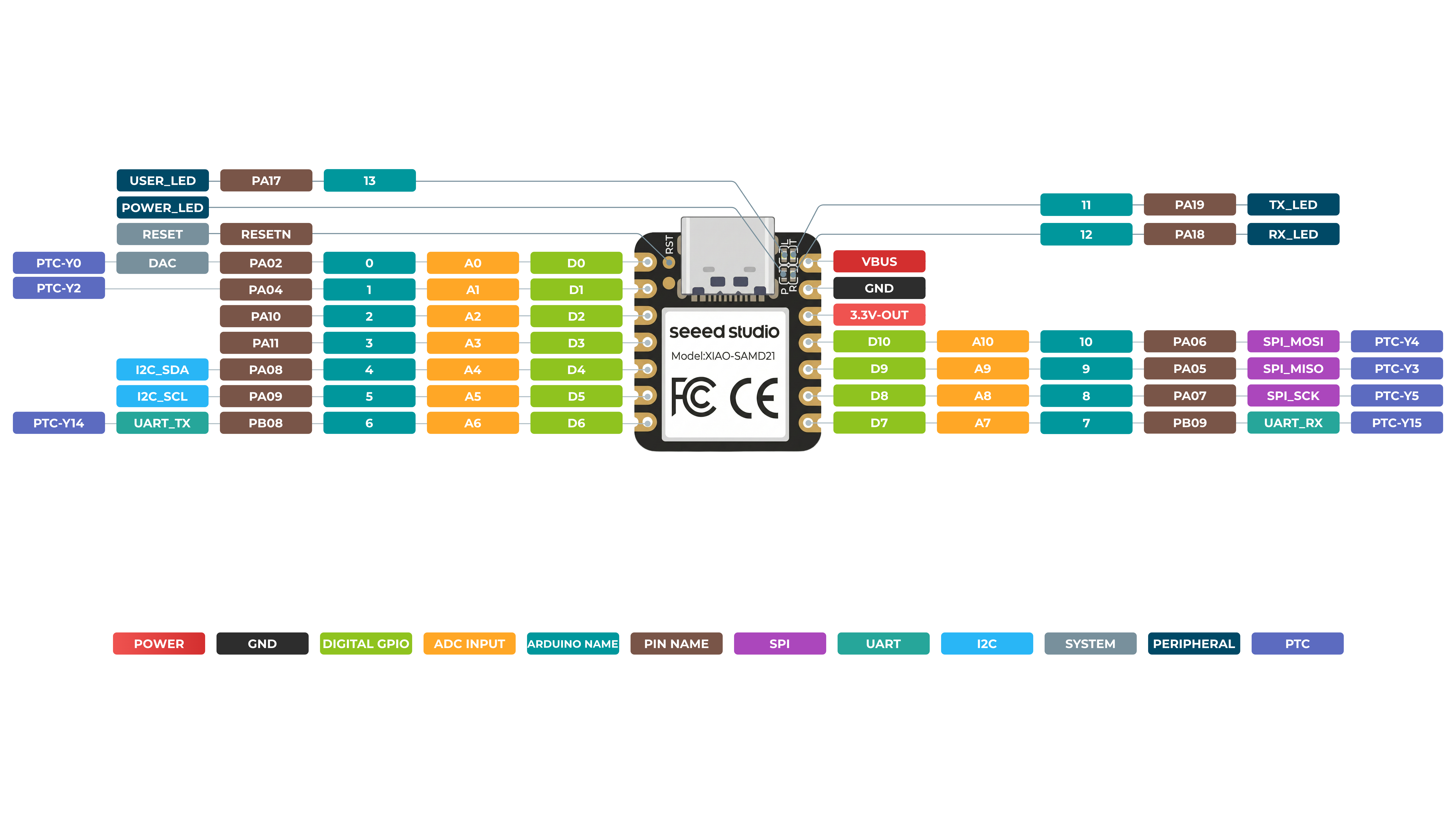
Seeed Studio XIAO SAMD21 具有 14 个引脚,可用作 11 个数字接口、11 个模拟接口、10 个 PWM 接口(d1-d10)、1 个 DAC 输出引脚 D0、1 个 SWD 焊盘接口、1 个 I2C 接口、1 个 SPI 接口、1 个 UART 接口,通过引脚复用实现串口通信指示灯(T/R)、闪烁灯(L)。LED(Power、L、RX、TX)的颜色分别为绿色、黄色、蓝色和蓝色。此外,Seeed Studio XIAO SAMD21 具有一个 Type-C 接口,可用于供电和下载代码。板上有两个复位焊盘,你可以将它们短接来复位开发板。
文档
关于 Seeed Studio XIAO SAMD21 的使用有两份文档,侧重点不同,请参考下表:
| Seeed 官方文档 | Nanase 编写的文档 |
|---|---|
| 引脚图 | 接口 |
| Seeed Studio XIAO SAMD21 入门指南 | Seeed Studio XIAO SAMD21 搭配 MicroSD 卡(SPI) |
| Seeed Studio XIAO SAMD21 GPIO 使用方法 | Seeed Studio XIAO SAMD21 搭配 GPS(UART) |
| Seeed Studio XIAO SAMD21 资源 | 单周期 IOBUS |
在 Seeed Studio XIAO SAMD21 上使用 CircuitPython
特性
- 强大的 CPU:ARM® Cortex®-M0+ 32 位 48MHz 微控制器(SAMD21G18),带有 256KB Flash、32KB SRAM。
- 兼容性灵活:兼容 Arduino IDE。
- 项目操作便捷:面包板友好。
- 体积小巧:尺寸如拇指般小(21x17.8mm),适用于可穿戴设备和小型项目。
- 多种开发接口:11 个数字/模拟引脚,10 个 PWM 引脚,1 个 DAC 输出,1 个 SWD 焊盘接口,1 个 I2C 接口,1 个 UART 接口,1 个 SPI 接口。
规格参数
| 产品名称 | Seeed Studio XIAO SAMD21 |
|---|---|
| 芯片组 | Microchip SAMD21G18 |
| 处理器 | 最高运行频率 48 MHz 的 ARM Cortex-M0+ 处理器 |
| RAM | 32KB SRAM |
| Flash | 256KB Flash |
| 接口 | GPIO 引脚 x14 数字引脚 x11 模拟引脚 x11 DAC x1 I2C x1 UART x1 SPI x1 |
| 板载 | 用户 LED x1 电源 LED x1 串口通信状态 LED(TX/RX 指示灯)x2 |
| 无线连接 | / |
| 电源 | 输入电压(Type-C):5V 输入电压(BAT):5V |
| 最大输出 | 5V@500mA 3.3V@200mA |
| 软件兼容性 | Arduino、PlatformIO、MicroPython、CircuitPython、Zephyr XIAO 系列展示 - Seeed Studio Wiki |
| 工作温度 | -40 至 85°C |
| 尺寸 | 21×17.8mm |
| 型号 | Seeed Studio XIAO SAMD21(预焊接)- Seeed Studio Seeed Studio XIAO SAMD21 - Arduino Microcontroller - SAMD21 Cortex M0+(3 片装)- Seeed Studio |
硬件概述
正面
背面
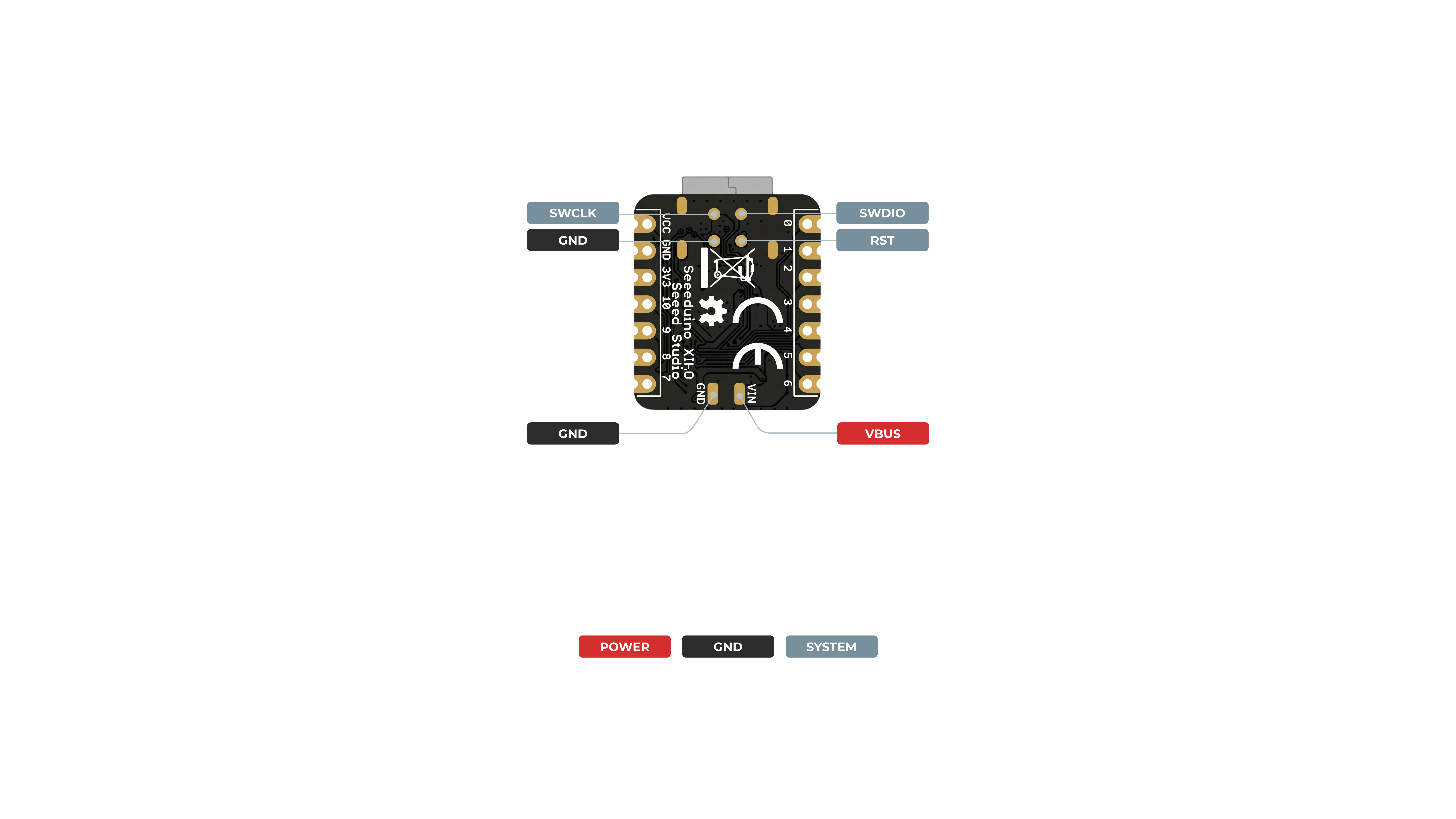
对于通用 I/O 引脚: MCU 的工作电压为 3.3V。如果连接到通用 I/O 引脚的输入电压高于 3.3V,可能会导致芯片损坏。
对于电源引脚: 板载的 DC-DC 转换电路可以将 5V 电压转换为 3.3V,从而允许通过 VIN-PIN 和 5V-PIN 使用 5V 电源为设备供电。
必须明确的是,XIAO SAMD21 背面的 VIN 和 GND 焊盘并非用于直接连接电池,尤其不是可充电锂电池(LiPo/Li-Ion)。该开发板缺少安全运行所需的关键电池管理电路。这些焊盘只是一个替代电源输入点,会绕过板载的保护二极管。如果你希望使用电池为项目供电,必须使用专用的外部电池管理模块,该模块需提供充电和保护功能,然后将该模块的稳压输出连接到 XIAO 的 5V 引脚。
请注意使用安全,请不要撬起屏蔽罩。
引脚映射
| XIAO 引脚 | 功能 | 芯片引脚 | 描述 |
|---|---|---|---|
| 5V | VBUS | 电源输入/输出 | |
| GND | |||
| 3V3 | 3V3_OUT | 电源输出 | |
| D0 | 模拟 | PA02 | GPIO,ADC |
| D1 | 模拟 | PA04 | GPIO,ADC |
| D2 | 模拟 | PA10 | GPIO,ADC |
| D3 | 模拟 | PA11 | GPIO,ADC |
| D4 | 模拟,SDA | PA08 | GPIO,I2C 数据,ADC |
| D5 | 模拟,SCL | PA09 | GPIO,I2C 时钟,ADC |
| D6 | 模拟,TX | PB08 | GPIO,UART 发送,ADC |
| D7 | 模拟,RX | PB09 | GPIO,UART 接收,ADC |
| D8 | 模拟,SPI_SCK | PA07 | GPIO,SPI 时钟,ADC |
| D9 | 模拟,SPI_MISO | PA05 | GPIO,SPI 数据,ADC |
| D10 | 模拟,SPI_MOSI | PA06 | GPIO,SPI 数据 |
| Reset | RES | 复位 | |
| TX_LED | PA19 | TX_LED | |
| RX_LED | PA18 | RX_LED | |
| Power_LED | VBUS | CHG-LED_Red | |
| USER_LED | PA17 | 用户指示灯_黄色 |
进入 Bootloader 模式
有时在用户烧录程序失败时,Seeed Studio XIAO SAMD21 的端口可能会消失。我们可以通过以下操作来解决这个问题:
- 将 Seeed Studio XIAO SAMD21 连接到电脑。
- 使用镊子或导线将图中的 RST 焊盘短接两次。
- 橙色 LED 灯会闪烁并点亮。
此时,芯片进入 Bootloader 模式,烧录端口会再次出现。由于 samd21 芯片有两个分区,一个是 Bootloader,另一个是用户程序。产品在出厂时会在系统存储器中烧录一段 bootloader 代码。我们可以通过执行上述步骤在两种模式之间切换。
复位
如果你想复位 Seeed Studio XIAO SAMD21,请执行以下步骤:
- 将 Seeed Studio XIAO SAMD21 连接到电脑。
- 使用镊子或导线将 RST 焊盘只短接一次
- 橙色 LED 灯会闪烁并点亮。
请注意:板载 LED 的行为与 Arduino 上的相反。在 Seeed Studio XIAO SAMD21 上,引脚需要被拉低,而在其他微控制器上则需要被拉高。
中断
Seeed Studio XIAO SAMD21 上的所有引脚都支持中断,但有两个引脚不能同时使用:5 号引脚和 7 号引脚。关于中断的更多细节请查看这里。
引脚复用
我们不需要自己配置引脚,使用引脚后可以直接调用函数。
数字输入和输出
- 使用引脚 6 作为数字引脚:
const int buttonPin = 6;     // the number of the pushbutton pin
const int ledPin =  13;      // the number of the LED pin

int buttonState = 0;         // variable for reading the pushbutton status

void setup() {
  // initialize the LED pin as an output:
  pinMode(ledPin, OUTPUT);
  // initialize the pushbutton pin as an input:
  pinMode(buttonPin, INPUT);
}

void loop() {
  // read the state of the pushbutton value:
  buttonState = digitalRead(buttonPin);

  // check if the pushbutton is pressed. If it is, the buttonState is HIGH:
  if (buttonState == HIGH) {
    // turn LED on:
    digitalWrite(ledPin, HIGH);
  } else {
    // turn LED off:
    digitalWrite(ledPin, LOW);
  }
}
AnalogRead
- 使用引脚 6 作为模拟引脚:
void setup() {
  // declare the ledPin as an OUTPUT:
  pinMode(ledPin, OUTPUT);
}

void loop() {
  // read the value from the sensor:
  sensorValue = analogRead(sensorPin);
  // turn the ledPin on
  digitalWrite(ledPin, HIGH);
  // stop the program for <sensorValue> milliseconds:
  delay(sensorValue);
  // turn the ledPin off:
  digitalWrite(ledPin, LOW);
  // stop the program for for <sensorValue> milliseconds:
  delay(sensorValue);
}
串口
- 使用引脚 6 作为 UART 的 TX 引脚(UART 的 RX 引脚为引脚 7):
void setup() {
    Serial1.begin(115200);
    while (!Serial);
}

void loop() {
    Serial1.println("Hello,World");
    delay(1000);
}
I2C
- 使用引脚 5 作为 IIC 的 SCL 引脚(IIC 的 SDA 引脚为引脚 4):
// Wire Master Writer
// by Nicholas Zambetti <http://www.zambetti.com>

// Demonstrates use of the Wire library
// Writes data to an I2C/TWI slave device
// Refer to the "Wire Slave Receiver" example for use with this

// Created 29 March 2006

// This example code is in the public domain.


#include <Wire.h>

void setup()
{
  Wire.begin(); // join i2c bus (address optional for master)
}

byte x = 0;

void loop()
{
  Wire.beginTransmission(4); // transmit to device #4
  Wire.write("x is ");        // sends five bytes
  Wire.write(x);              // sends one byte
  Wire.endTransmission();    // stop transmitting
  x++;
  delay(500);
}
SPI
- 使用引脚 8 作为 SPI 的 SCK 引脚(SPI 的 MISO 引脚为引脚 9,MOSI 引脚为引脚 10):
#include <SPI.h>
const int CS = 7;
void setup (void) {
   digitalWrite(CS, HIGH); // disable Slave Select
   SPI.begin ();
   SPI.setClockDivider(SPI_CLOCK_DIV8);//divide the clock by 8
}

void loop (void) {
   char c;
   digitalWrite(CS, LOW); // enable Slave Select
   // send test string
   for (const char * p = "Hello, world!\r" ; c = *p; p++) {
      SPI.transfer (c);
   }
   digitalWrite(CS, HIGH); // disable Slave Select
   delay(2000);
}
QTouch
关于如何使用 QTouch,我们提供了一个示例项目:How to Make a Fruit Piano on Seeed Studio XIAO SAMD21 ’s Q-Touch Function。
模拟输入和输出
虽然它仍然具有基于 PWM 的“模拟输出”,但 SAMD21 还具有真正的模拟输出,即数模转换器(DAC)。该模块可以产生 0 到 3.3V 之间的模拟电压。它可以用来产生更自然声音的音频,或者作为一种“数字电位器”来控制模拟设备。
DAC 仅在 Arduino 引脚 A0 上可用,并通过 analogWrite(A0, <value>) 控制。DAC 最多可以设置为 10 位分辨率(请确保在 setup 中调用 analogWriteResolution(10)),这意味着 0 到 1023 之间的数值会将电压设置在 0 到 3.3V 之间的某个值。
除了 DAC 之外,SAMD21 的 ADC 通道也不同于 ATmega328:它们支持最高 12 位分辨率。这意味着模拟输入值可以在 0-4095 之间变化,对应 0 到 3.3V 之间的电压。要在 12 位模式下使用 ADC,请确保在 setup 中调用 analogReadResolution(12)。
串口绘图 DAC
下面是一个同时演示 DAC 和 ADC 的示例。要搭建这个实验,将 A0 连接到 A1 —— 我们用模拟电压驱动 A0,然后用 A1 读取它。这是我们在教程中使用过的最简单电路:
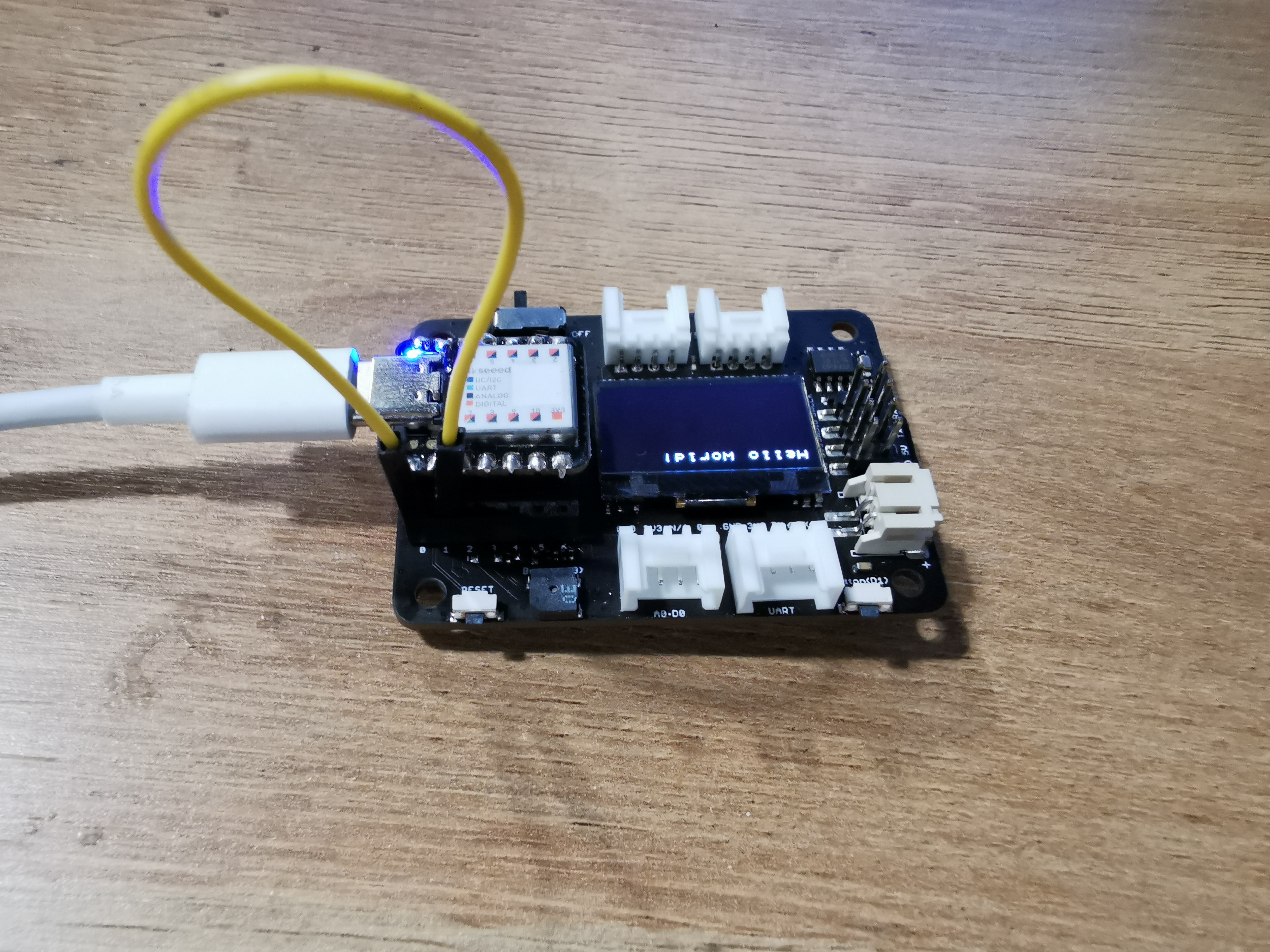
Seeed Studio XIAO SAMD21 使用的是 Seeed Studio XIAO SAMD21 expansion board
该示例在 A0 上产生一个正弦波输出,电压范围为 0 到 3.3V。然后使用 A1 将该输出读入其 ADC,并将其转换为 0 到 3.3V 之间的电压。
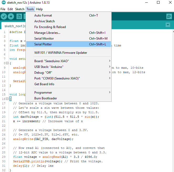
当然,你可以打开串口监视器来查看电压值的流动。但如果通过文本很难想象正弦波的形状,可以通过依次点击 Tools > Serial Plotter 来查看 Arduino 新的 Serial Plotter。
感谢 Aleksei Tertychnyi 提交代码,所有相关功能均由他开发并贡献。
#define DAC_PIN A0 // Make code a bit more legible
float x = 0; // Value to take the sin of
float increment = 0.02;  // Value to increment x by each time
// Frequency of sine wave is about 1.37 Hz

void setup()
{
  analogWriteResolution(10); // Set analog out resolution to max, 10-bits
  analogReadResolution(12); // Set analog input resolution to max, 12-bits

  Serial.begin(9600);
}

void loop()
{
  // Generate a voltage value between 0 and 1023.
  // Let's scale a sin wave between those values:
  // Offset by 511.5, then multiply sin by 511.5.
  int dacVoltage = (int)(511.5 + 511.5 * sin(x));
  x += increment; // Increase value of x

  // Generate a voltage between 0 and 3.3V.
  // 0= 0V, 1023=3.3V, 512=1.65V, etc.
  analogWrite(DAC_PIN, dacVoltage);

  // Now read A1 (connected to A0), and convert that
  // 12-bit ADC value to a voltage between 0 and 3.3.
  float voltage = analogRead(A1) * 3.3 / 4096.0;
  Serial.println(voltage); // Print the voltage.
  delay(1); // Delay 1ms
}
结果

入门指南
硬件
所需材料
- Seeed Studio XIAO SAMD21 x1
- 电脑 x1
- USB Type-C 线 x1
有些 USB 线只能供电,不能传输数据。如果你没有 USB 线,或者不知道你的 USB 线是否可以传输数据,你可以查看 seeed USB type C support USB 3.1。
-
步骤 1. 准备一块 Seeed Studio XIAO SAMD21 和一根 Type-C 线。
-
步骤 2. 将 Seeed Studio XIAO SAMD21 连接到你的电脑。然后黄色电源 LED 应该会亮起。
软件
如果这是你第一次使用 Arduino,我们强烈建议你参考 Getting Started with Arduino
- 步骤 1. 你需要安装 Arduino 软件。
启动 Arduino 应用程序
双击你之前下载的 Arduino 应用程序(arduino.exe)。
如果 Arduino 软件以其他语言加载,你可以在首选项对话框中更改它。详情请参阅 Arduino Software (IDE) 页面。
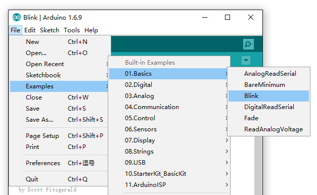
- 步骤 2. 打开 Blink 示例
打开 LED 闪烁示例草图:File > Examples >01.Basics > Blink。
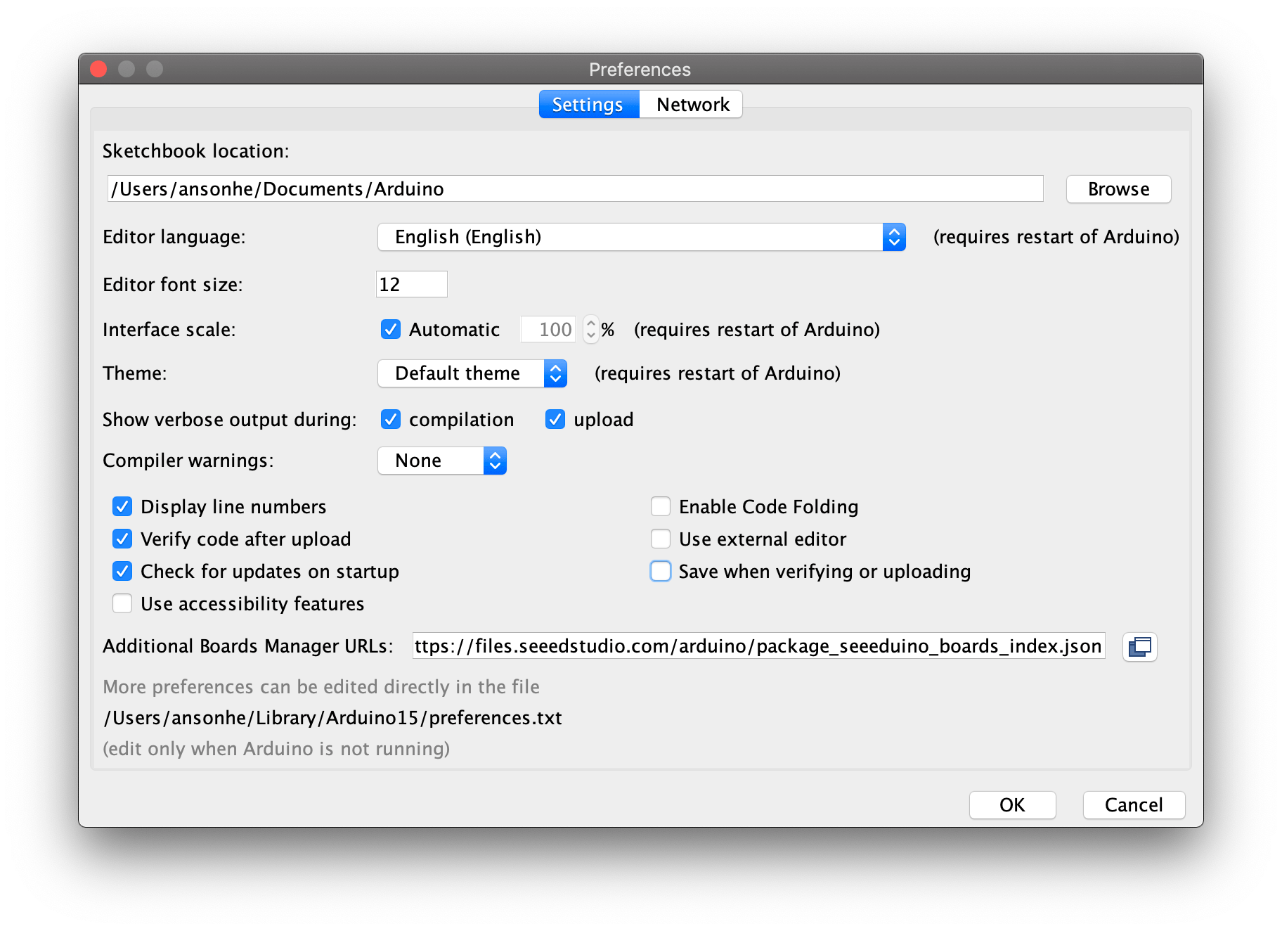
- 步骤 3. 将 Seeeduino 添加到你的 Arduino IDE
点击 File > Preference,并在 Additional Boards Manager URLs 中填入以下 URL:
https://files.seeedstudio.com/arduino/package_seeeduino_boards_index.json
点击 Tools-> Board-> Boards Manager...,在搜索框中输入关键字“Seeed Studio XIAO SAMD21”。此时会出现 “Seeed SAMD Boards”。安装它。

- 步骤 4. 选择你的开发板和端口
安装开发板后,点击 Tools-> Board,找到“Seeed Studio XIAO”并选择它。现在你已经在 Arduino IDE 中完成了 Seeed Studio XIAO SAMD21 开发板的设置。

在 Tools | Serial Port 菜单中选择 Arduino 开发板的串口设备。它很可能是 COM3 或更高(COM1 和 COM2 通常保留给硬件串口)。要确认的话,你可以断开 Arduino 开发板并重新打开该菜单;消失的那一项应该就是 Arduino 开发板。重新连接开发板并选择该串口。

- 步骤 5. 上传程序
现在,只需点击环境中的 “Upload” 按钮。等待几秒钟,如果上传成功,状态栏中会出现 “Done uploading.” 的消息。
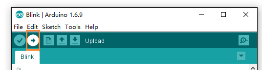
上传完成几秒钟后,你应该会看到板子上的 13 号引脚(L)LED 开始闪烁(橙色)。如果是这样,恭喜你!你已经成功运行 Arduino。如果遇到问题,请查看故障排除建议。
flash 的最大容量为 8KB,更多信息请参阅资源中的 ATSAMD218A-MU 数据手册
示例应用
-
如何使用 Raspberry Pi 修复变砖的 xiao。感谢 John_Doe 的分享。
资源
硬件设计
- 📄[数据手册] Atmel SAMD21G18 数据手册
- 📄[原理图] XIAO SAMD21 原理图
- 🗃️[PCB 设计文件]
- 🗃️[PCB 设计库]
- 📄[引脚分布表] XIAO SAMD21 引脚分布表
机械设计
- 📄[2D 尺寸] DXF 格式的 XIAO 尺寸
- 📄[3D 模型] XIAO SAMD21 3D 模型
软件与工具
- 📄[出厂固件] XIAO SAMD21 出厂固件
课程资源
技术支持与产品讨论
感谢您选择我们的产品!我们将为您提供多种支持,以确保您在使用我们产品的过程中尽可能顺利。我们提供多种沟通渠道,以满足不同的偏好和需求。