Arduinoプロジェクト用Grove Beginner Kit
プロジェクト1: 侵入アラーム
概要
このWikiでは、侵入アラームの作り方を紹介します。
特徴
- PIRモーションセンサーがエリア内の人を検知し、アラームを作動させます。
必要なコンポーネント
ハードウェア接続
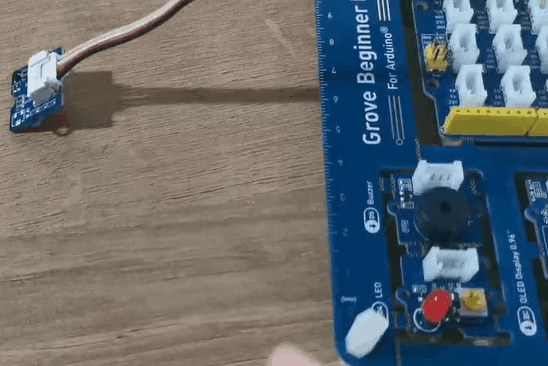
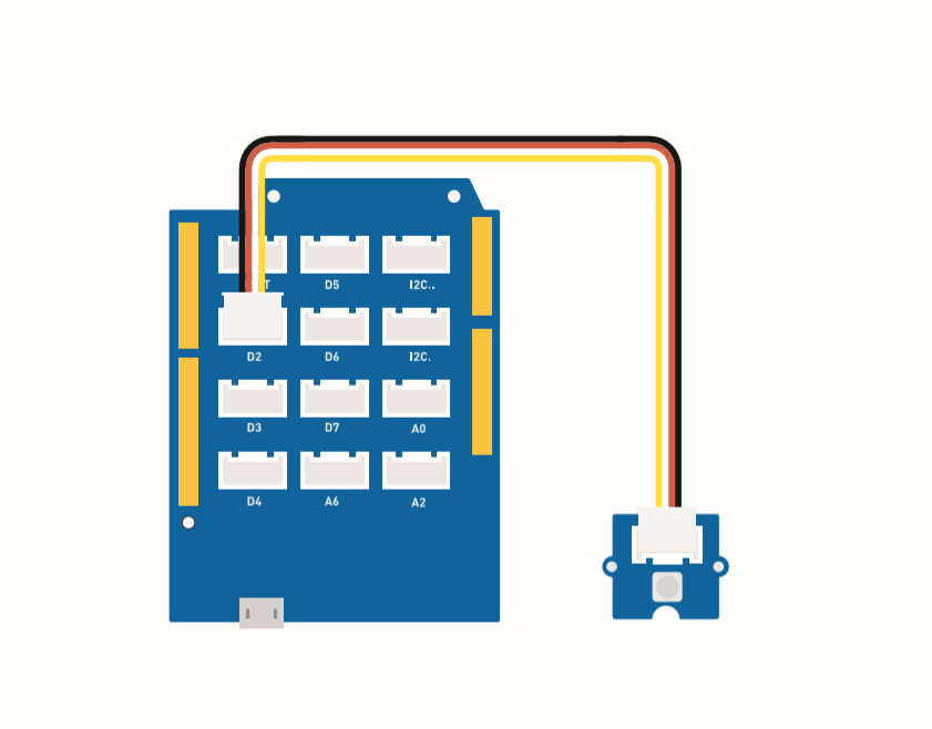
各センサーをボードに接続する際は、同じ色のラインに従って接続してください。PIRモーションセンサーのGroveケーブルをD2に接続します。
組み立て手順
ブザー(D5)とLED(D4)はボードに組み込まれています。
Arduino手順
ステップ1. Arduino IDEをダウンロードします。
ステップ2. 接続図に従って、すべてのセンサーをボードに接続します。
ステップ3. Mini PIRモーションセンサーを検知する場所に設置します。
ステップ4. 以下のコードをArduino IDEにコピーしてアップロードします。
コード
#define PIR_MOTION_SENSOR 2// モジュールからの信号を受信するためにピン2を使用

int BuzzerPin = 5;     // D5をブザーとして設定
int LED_RAD = 4;       // D4をLEDとして設定

void setup() {
  Serial.begin(9600);
  pinMode(PIR_MOTION_SENSOR, INPUT);
  pinMode(BuzzerPin, OUTPUT);
  pinMode(LED_RAD, OUTPUT);
}

void loop() {

  if (digitalRead(PIR_MOTION_SENSOR)) {
    analogWrite(BuzzerPin, 100);
    digitalWrite(LED_RAD, HIGH);
    delay(3000);
    analogWrite(BuzzerPin, 0);
    digitalWrite(LED_RAD, LOW);
    delay(4000);
  }

}
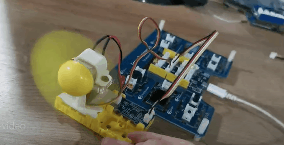
プロジェクト2: 揺れる扇風機
概要
このWikiでは、部屋を涼しく保つためのミニ扇風機の作り方を紹介します。
特徴
- 自動で揺れる扇風機
必要なコンポーネント
ハードウェア接続
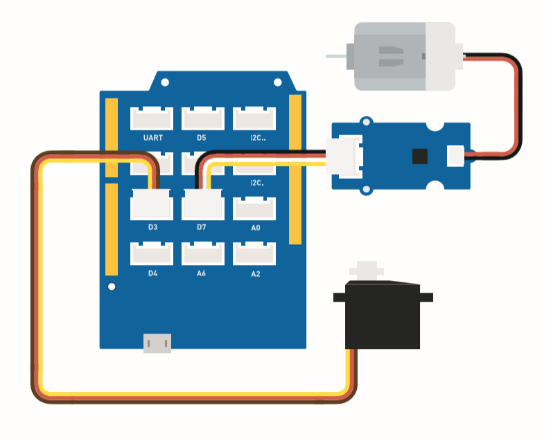
ファンのGroveケーブルをD7に、サーボのGroveケーブルをD3に接続してください。
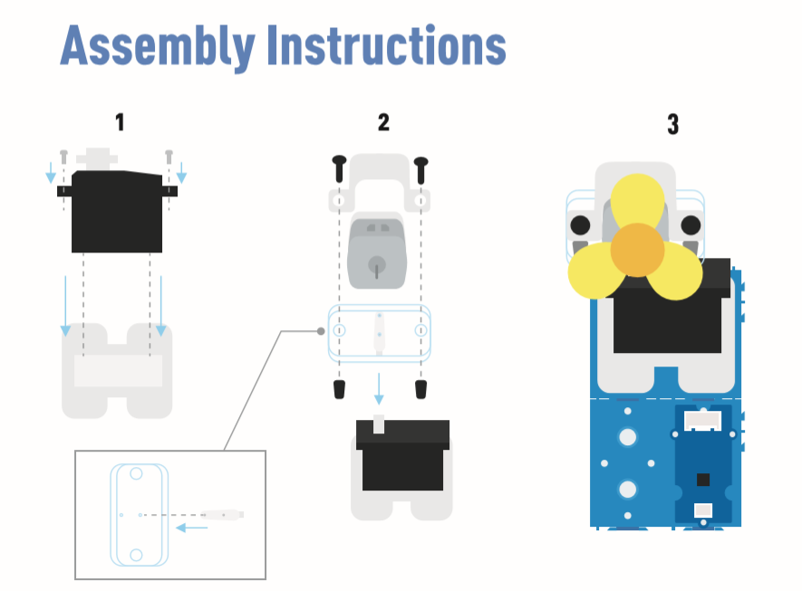
組み立て手順
Arduino手順
ステップ1. Arduino IDEをダウンロードします。
ステップ2. 以下のコードをArduino IDEにコピーします。
ステップ3. 現在のポートを選択します: Tools -> Port -> COM (番号)
ステップ4. コードをアップロードします。
扇風機を安全な位置に設置してください。
コード
#include <Servo.h>

Servo myservo;  // サーボを制御するためのサーボオブジェクトを作成

int pos = 0;    // サーボの位置を格納する変数
int fanPin = 7;  // D6を制御スイッチとして設定
int fanState = LOW;

void setup() {
    Serial.begin(9600);
    myservo.attach(3);  // ピン2にサーボオブジェクトを接続
    pinMode(fanPin, OUTPUT);
}

void loop() {

 fanState = HIGH;
 digitalWrite(fanPin, fanState);

   for (pos = 0; pos <= 100; pos += 1) { // 0度から100度まで移動
    // 1度ずつ移動
    myservo.write(pos);              // サーボを'pos'の位置に移動
    delay(40);                       // サーボが位置に到達するまで15ms待機
  }
  for (pos = 100; pos >= 0; pos -= 1) { // 100度から0度まで移動
    myservo.write(pos);              // サーボを'pos'の位置に移動
    delay(40);                       // サーボが位置に到達するまで15ms待機
  }
}
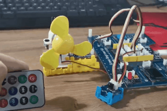
プロジェクト 3: リモート制御式振動ファン
概要
このWikiでは、リモート制御式振動ファンの作り方を紹介します。
特徴
-
ファンの電源はコントローラーで制御されます。
-
ファンの振動方向はリモート制御で操作可能です。
必要な部品
ハードウェア接続
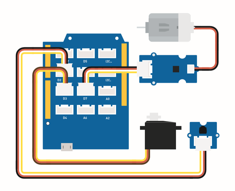
各センサーをボードに接続する際は、同じ色のラインに従って接続してください。ファンのGroveケーブルをD7に、サーボのGroveケーブルをD3に、IRのGroveケーブルをD2に接続してください。
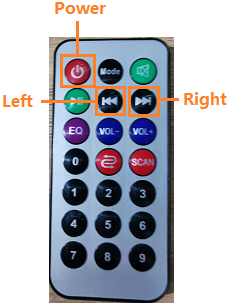
これはコントローラーのボタン機能です。
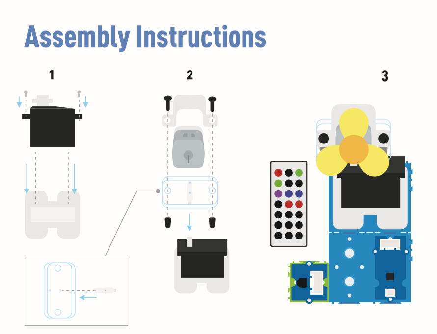
組み立て手順
Arduinoの手順
ステップ 1. 接続図に従って、すべてのセンサーをボードに接続します。
ステップ 2. Arduino IDE をダウンロードします。
ステップ 3. Sketch -> Include Library -> Manage Libraries に移動し、IRremote を検索してインストールします。
ステップ 4. 以下のコードをArduino IDEにコピーしてアップロードします。
ステップ 5. ファンを安全な位置に配置し、ボタンを押して安全に動作することを確認してください。
Arduinoのライブラリをインストールする方法については、ライブラリのインストール方法 を参照してください。
コード
#include <IRremote.h>
#include <Servo.h>

Servo myservo;  // サーボオブジェクトを作成してサーボを制御
int RECV_PIN = 2; // ピン2をIR制御として設定

IRrecv irrecv(RECV_PIN);

decode_results results;

int pos = 90;    // サーボ位置を格納する変数
int fanPin = 7;  // D6を制御スイッチとして設定
int fanState = LOW;
int IO = 0;

void setup()
{
  Serial.begin(9600);
  Serial.println("IRinを有効化中");  // IR有効化を通知
  irrecv.enableIRIn(); // 受信機を開始
  Serial.println("IRinが有効化されました");
  myservo.attach(3);  // ピン2にサーボオブジェクトを接続
  pinMode(fanPin, OUTPUT);

}

//  power_encode 2155829415     左  2155870215  右  2155821255

void loop() {
  if (irrecv.decode(&results)) { // IR信号を確認
    if (results.value == 2155829415) {    // 電源オン/オフ
      IO++;
      if (IO % 2 == 0) {
        fanState = HIGH;
        digitalWrite(fanPin, fanState);
        delay(100);
      }
      else {
        fanState = LOW;
        digitalWrite(fanPin, fanState);
        delay(100);
      }
    }

    if (results.value == 2155821255 ) {    // ファンを左に振動
      for (pos; pos <= 89; pos += 1) { // 0度から90度まで移動
        // 1度ずつ移動
        myservo.write(pos);              // サーボを変数 'pos' の位置に移動

        delay(40);                       // サーボが位置に到達するまで15ms待機
        if (irrecv.decode(&results)) {
          irrecv.resume();
          if (results.value == 2155870215)
            break;
        }
      }
    }

    if (results.value == 2155870215 ) {    // ファンを右に振動
      for (pos; pos >= 1; pos -= 1) { // 90度から0度まで移動
        myservo.write(pos);              // サーボを変数 'pos' の位置に移動
        delay(40);                       // サーボが位置に到達するまで15ms待機

        if (irrecv.decode(&results)) {
          irrecv.resume();
          if (results.value == 2155821255)
            break;
        }
      }
    }
    Serial.println(pos);
    Serial.println(results.value, HEX);
    Serial.println(results.value);
    irrecv.resume();                    // 次の指示を受信

  }
  delay(100);
}
プロジェクト 4: スマート加湿器
概要
このウィキでは、室内の湿度を正常に保つための水の霧化方法について説明します。
特徴
-
湿度が低い場合に自動的に水を霧化します。
-
温度と湿度をリアルタイムで表示します。
必要なコンポーネント
ハードウェア接続
各センサーをボードに接続する際は、同じ色の線を使用してください。
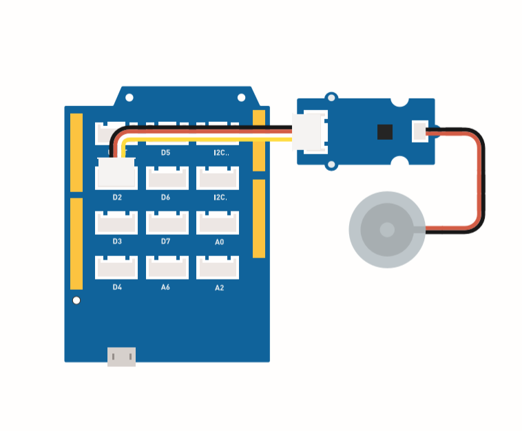
Grove 水霧化モジュールのケーブルを D2 に接続します。
組み立て手順
Arduino 手順
ステップ 1. 接続図に従って、すべてのセンサーをボードに接続します。
ステップ 2. Arduino IDE をダウンロードします。
ステップ 3. Sketch -> Include Library -> Manage Libraries に移動し、U8g2 を検索してインストールします。
ステップ 4. Grove_Temperature_And_Humidity_Sensor ライブラリ をダウンロードしてインストールします。
ステップ 5. 以下のコードを Arduino IDE にコピーしてアップロードします。
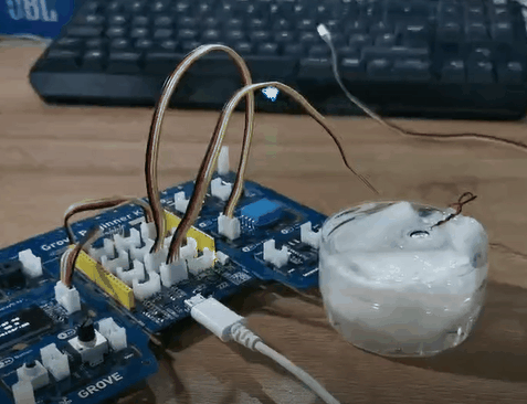
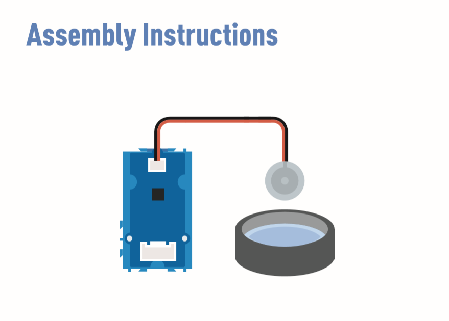
ステップ 6. 水を満たした容器を用意し、水霧化モジュールを水に浮かべます。
Arduino 用ライブラリのインストール方法については、ライブラリのインストール方法 を参照してください。
水の上にティッシュを置き、水霧化モジュールを浮かせてください。ティッシュの役割は、水をトランスデューサーに導き、トランスデューサーの上部を水面上に保つことです。
コード
#include <Arduino.h>
#include <U8x8lib.h>

#include "DHT.h"
#define DHTTYPE DHT11   // DHT 11
#define DHTPIN 3     // 接続されているピン
DHT dht(DHTPIN, DHTTYPE);

#include <Wire.h>

U8X8_SSD1306_128X64_NONAME_HW_I2C u8x8(/* reset=*/ U8X8_PIN_NONE);

void setup(void) {
  Serial.begin(115200);
  u8x8.begin();
  u8x8.setFlipMode(1);
  Wire.begin();
  dht.begin();
  pinMode(2,INPUT);
}

void loop(void) {
  float temp_hum_val[2] = {0};
  int b;
  int c;
  if (!dht.readTempAndHumidity(temp_hum_val)) {
     b = temp_hum_val[0];
     c = temp_hum_val[1];
  }
  else{
    Serial.println("温度と湿度の値を取得できませんでした。");
    }
  u8x8.setFont(u8x8_font_chroma48medium8_r);   // 適切なフォントを選択
  u8x8.setCursor(0, 0);
  u8x8.print("温度: ");
  u8x8.setCursor(5, 0);
  u8x8.print(c);
  u8x8.setCursor(8, 0);
  u8x8.print("*C");
  u8x8.setCursor(0, 10);
  u8x8.print("湿度: ");
  u8x8.setCursor(5, 10);
  u8x8.print(b);
  u8x8.setCursor(8, 10);
  u8x8.print("%");
  u8x8.setCursor(0, 20);
  u8x8.print("霧化器: ");

  if(b > 70){
  u8x8.setCursor(9, 20);
  u8x8.print("OFF");
  digitalWrite(2, LOW);    // 霧化停止
  }
  if(b <= 70) {
  u8x8.setCursor(9, 20);
  u8x8.print("ON ");
  digitalWrite(2, HIGH);   // 霧化開始
    }
  delay(1000);

}
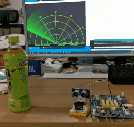
プロジェクト 5: 超音波レーダー
概要
このWikiでは、物体と距離を検出するための超音波レーダーの作り方を紹介します。
特徴
-
物体の距離を検出する
-
周囲に物体が存在するかをスキャンする
必要なコンポーネント
ハードウェア接続
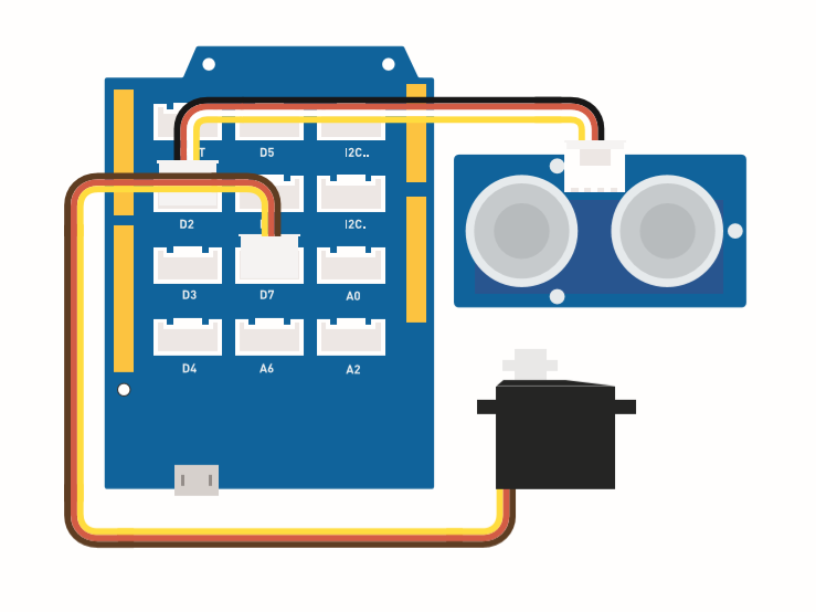
以下の図に従って、超音波センサーのGroveケーブルをD2に接続し、サーボをD7に接続してください。
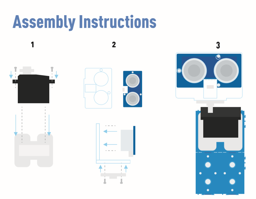
組み立て手順
Arduino手順
ステップ 1. 接続図に従って、ケーブルをポートに差し込んでください。
ステップ 2. Arduino IDE をダウンロードしてください。
ステップ 3. Processing をダウンロードしてください。
ステップ 4. Githubから UltrasonicRanger ライブラリをダウンロードしてください。
ステップ 5. レーダーコードをコピーしてArduino IDEに貼り付け、アップロードしてください。
ステップ 6. レーダースキャンマップを表示するために Processing をダウンロードしてください。
ステップ 7. レーダー用のProcessingコードをコピーしてProcessingに貼り付けてください。
ステップ 8. サーボがスイングを開始したら、Processingソフトウェアで再生をクリックしてください。
ライブラリのインストール方法がわからない場合は、こちら をクリックしてください。
レーダーコード
#include <Servo.h>
#include "Ultrasonic.h"

int distance;
Servo myServo;

Ultrasonic ultrasonic(2);

void setup() {
    Serial.begin(9600);
    myServo.attach(7);
}
void loop() {

    for(int pos = 15; pos <= 165; pos += 1){
        myServo.write(pos);
        delay(30);
        distance = ultrasonic.MeasureInCentimeters();
        Serial.print(pos);
        Serial.print(",");
        Serial.print(distance);
        Serial.print(".");
    }

    for(int pos = 165; pos >= 15; pos -= 1){
        myServo.write(pos);
        delay(30);
        distance = ultrasonic.MeasureInCentimeters();
        Serial.print(pos);
        Serial.print(",");
        Serial.print(distance);
        Serial.print(".");
    }
}
レーダー用Processingコード
import processing.serial.*; // シリアル通信用ライブラリをインポート
import java.awt.event.KeyEvent; // シリアルポートからデータを読み取るためのライブラリをインポート
import java.io.IOException;
Serial myPort; // シリアルオブジェクトを定義
// 変数を定義
String angle="";
String distance="";
String data="";
String noObject;
float pixsDistance;
int iAngle, iDistance;
int index1=0;
int index2=0;
PFont orcFont;
void setup() {

 size (1000, 720); // ***画面解像度に合わせて変更してください***
 smooth();
 myPort = new Serial(this,"COM14", 9600); // シリアル通信を開始
 myPort.bufferUntil('.'); // シリアルポートからデータを'.'まで読み取る
 orcFont = loadFont("AgencyFB-Bold-48.vlw");
}
void draw() {

  fill(98,245,31);
  textFont(orcFont);
  // モーションブラーと移動する線のスローフェードをシミュレート
  noStroke();
  fill(0,4);
  rect(0, 0, width, height-height*0.065);

  fill(98,245,31); // 緑色
  // レーダー描画用の関数を呼び出し
  drawRadar();
  drawLine();
  drawObject();
  drawText();
}
void serialEvent (Serial myPort) { // シリアルポートからデータの読み取りを開始
  // シリアルポートから'.'までのデータを読み取り、文字列変数"data"に格納
  data = myPort.readStringUntil('.');
  data = data.substring(0,data.length()-1);

  index1 = data.indexOf(","); // ','の位置を見つけて変数"index1"に格納
  angle= data.substring(0, index1); // 角度データを取得
  distance= data.substring(index1+1, data.length()); // 距離データを取得

  // 文字列変数を整数に変換
  iAngle = int(angle);
  iDistance = int(distance);
}
void drawRadar() {
  pushMatrix();
  translate(width/2,height-height*0.074); // 開始座標を新しい位置に移動
  noFill();
  strokeWeight(2);
  stroke(98,245,31);
  // 弧線を描画
  arc(0,0,(width-width*0.0625),(width-width*0.0625),PI,TWO_PI);
  arc(0,0,(width-width*0.27),(width-width*0.27),PI,TWO_PI);
  arc(0,0,(width-width*0.479),(width-width*0.479),PI,TWO_PI);
  arc(0,0,(width-width*0.687),(width-width*0.687),PI,TWO_PI);
  // 角度線を描画
  line(-width/2,0,width/2,0);
  line(0,0,(-width/2)*cos(radians(30)),(-width/2)*sin(radians(30)));
  line(0,0,(-width/2)*cos(radians(60)),(-width/2)*sin(radians(60)));
  line(0,0,(-width/2)*cos(radians(90)),(-width/2)*sin(radians(90)));
  line(0,0,(-width/2)*cos(radians(120)),(-width/2)*sin(radians(120)));
  line(0,0,(-width/2)*cos(radians(150)),(-width/2)*sin(radians(150)));
  line((-width/2)*cos(radians(30)),0,width/2,0);
  popMatrix();
}
void drawObject() {
  pushMatrix();
  translate(width/2,height-height*0.074); // 開始座標を新しい位置に移動
  strokeWeight(9);
  stroke(255,10,10); // 赤色
  pixsDistance = iDistance*((height-height*0.1666)*0.025); // センサーの距離をcmからピクセルに変換
  // 範囲を40cmに制限
  if(iDistance<40){
    // 角度と距離に応じて物体を描画
  line(pixsDistance*cos(radians(iAngle)),-pixsDistance*sin(radians(iAngle)),(width-width*0.505)*cos(radians(iAngle)),-(width-width*0.505)*sin(radians(iAngle)));
  }
  popMatrix();
}
void drawLine() {
  pushMatrix();
  strokeWeight(9);
  stroke(30,250,60);
  translate(width/2,height-height*0.074); // 開始座標を新しい位置に移動
  line(0,0,(height-height*0.12)*cos(radians(iAngle)),-(height-height*0.12)*sin(radians(iAngle))); // 角度に応じて線を描画
  popMatrix();
}
void drawText() { // 画面にテキストを描画

  pushMatrix();
  if(iDistance>40) {
  noObject = "範囲外";
  }
  else {
  noObject = "範囲内";
  }
  fill(0,0,0);
  noStroke();
  rect(0, height-height*0.0648, width, height);
  fill(98,245,31);
  textSize(25);

  text("10cm",width-width*0.3854,height-height*0.0833);
  text("20cm",width-width*0.281,height-height*0.0833);
  text("30cm",width-width*0.177,height-height*0.0833);
  text("40cm",width-width*0.0729,height-height*0.0833);
  textSize(40);
  text("物体: " + noObject, width-width*0.875, height-height*0.0277);
  text("角度: " + iAngle +" °", width-width*0.48, height-height*0.0277);
  text("距離: ", width-width*0.26, height-height*0.0277);
  if(iDistance<40) {
  text("        " + iDistance +" cm", width-width*0.225, height-height*0.0277);
  }
  textSize(25);
  fill(98,245,60);
  translate((width-width*0.4994)+width/2*cos(radians(30)),(height-height*0.0907)-width/2*sin(radians(30)));
  rotate(-radians(-60));
  text("30°",0,0);
  resetMatrix();
  translate((width-width*0.503)+width/2*cos(radians(60)),(height-height*0.0888)-width/2*sin(radians(60)));
  rotate(-radians(-30));
  text("60°",0,0);
  resetMatrix();
  translate((width-width*0.507)+width/2*cos(radians(90)),(height-height*0.0833)-width/2*sin(radians(90)));
  rotate(radians(0));
  text("90°",0,0);
  resetMatrix();
  translate(width-width*0.513+width/2*cos(radians(120)),(height-height*0.07129)-width/2*sin(radians(120)));
  rotate(radians(-30));
  text("120°",0,0);
  resetMatrix();
  translate((width-width*0.5104)+width/2*cos(radians(150)),(height-height*0.0574)-width/2*sin(radians(150)));
  rotate(radians(-60));
  text("150°",0,0);
  popMatrix();
}