Grove - 2-Channel SPDT Relay

The Grove - 2-Channel SPDT Relay has two single pole - double throw (SPDT) switches. It only requires low-voltage and low current signals to control those switches. Specifically, you can use 5V DC to control max.250V AC or 110V DC.
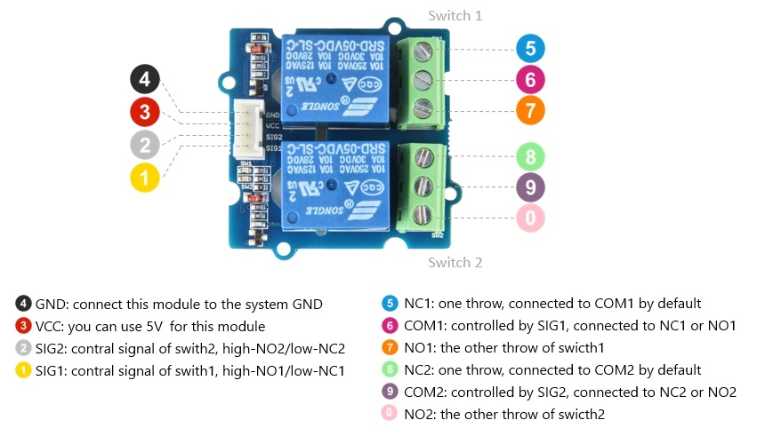
The best thing is that you can control the two channels separately. For instance, controlled by SIG1, you can connect the COM1 to NC1 or N01 as your wish. It is so convenient and reliable that it can be applied to massive products or projects which need to switch high voltage/high current devices.

Features
- High temperature resistant plastic shell
- High voltage load
- Low power consumption
- Long lasting
Specification
| Item | Value |
|---|---|
| Operating voltage | 5V |
| Nominal Coil Current | 89.3mA |
| TUV Certification Load | 10A 250VAC/ 10A 30VDC |
| UL Certification Load | 10A 125VAC/ 10A 28VDC |
| Max. Allowable Voltage | 250VAC/110VDC |
| Power Consumption | abt. 0.45W |
| Contact Resistance | 100mΩ Max. |
| Insulation Resistance | 100MΩ Min. (500VDC) |
| Max. ON/OFF Switching | 30 operation/min |
| Ambient Temperature | -40°C to +85°C |
| Operating Humidity | 45% to 85%RH |
| Contact Material | AgCdO |
| Input interface | Digital SIG1/SIG2 |
| Output Port | 3 Pins DIP Female Screw Terminal-Green |
Applications
- Domestic appliance
- office machine
- Remote control TV receiver
- monitor display
- audio equipment high rushing current use application
Hardware Overview
Pin Map
Schematic

K1 is the Relay module, there is a coil between pin1 and pin3 of K1. Defaultly, the COM1 will connect to NC1.If the pin3 of K1 connected to the grand, then this coil will be 'closed', so the COM1 will connect to NO1.
To open this coil, it requires about 90mA, however, normally the GPIO pin of Arduino only can afford 20mA(40mA max.). Therefor, we use a NPN transistors S9013 which can proviede 500mA.
The SIG1 is pulled down by the 10k R2, if there is no signal, the 'Gate' of Q1 will be 0v, and Q1 is turned off, so that the K1 will be 'opened'. If SIG1 becomes 5v, then the Q1 will be turned on. Pin3 of k1 will be connected to the GND of the system, for the K1 there will be 5V between pin3 and pin1, so the coil will be 'closed', and the COM1 will connect to NO1
The D3 is a flyback diode(kickback diode). A flyback diode is a diode connected across an inductor used to eliminate flyback, which is the sudden voltage spike seen across an inductive load when its supply current is suddenly reduced or interrupted. It is used in circuits in which inductive loads are controlled by switches, and in switching power supplies and inverters.
Platforms Supported
| Arduino | Raspberry Pi | |||
|---|---|---|---|---|
The platforms mentioned above as supported is/are an indication of the module's software or theoritical compatibility. We only provide software library or code examples for Arduino platform in most cases. It is not possible to provide software library / demo code for all possible MCU platforms. Hence, users have to write their own software library.
Getting Started
Play With Arduino
Hardware
Materials required
| Seeeduino V4.2 | Base Shield | Grove - 2-Channel SPDT Relay | Grove-LED x2 |
|---|---|---|---|
 |  |  |  |
| Get One Now | Get One Now | Get One Now | Get One Now |
1 Please plug the USB cable gently, otherwise you may damage the port. Please use the USB cable with 4 wires inside, the 2 wires cable can't transfer data. If you are not sure about the wire you have, you can click here to buy
2 Each Grove module comes with a Grove cable when you buy. In case you lose the Grove cable, you can click here to buy.
-
Step 1. Connect the SIG pin of the Grove-LED to the COM port of the Grove - 2-Channel SPDT Relay. Connect the GND pin of the Grove-LED to the GND of the Base Shield.
-
Step 2. Connect the NO port of the Grove - 2-Channel SPDT Relay to the 5V of the Base Shield. Connect the NC port of the Grove - 2-Channel SPDT Relay to the GND of the Base Shield.
Step 1. and Step 2. Connect the Grove LED GND to the system GND and the SIG to the COM port of the Relay. If the COM connect to NO(5v), the LED will turn on, and if the COM connect to NC(0V), the LED will turn of. We use two LEDs in this wiki, please make sure LED1 for the Switch1, and the LED2 for the Switch2.
-
Step 3. Connect the Grove - 2-Channel SPDT Relay to the D7 port of the Base Shield.
-
Step 4. Plug Grove - Base Shield into Seeeduino.
-
Step 5. Connect Seeeduino to PC via a USB cable.

Software
If this is the first time you work with Arduino, we strongly recommend you to see Getting Started with Arduino before the start.
- Step 1. Open the Arduino IDE and create a new file, then copy the following code into the new file.
#include <Arduino.h>
uint8_t channel1 = 7;
uint8_t channel2 = 8;
void setup() {
  pinMode(channel1, OUTPUT);
  pinMode(channel2, OUTPUT);
}
void loop() {
  digitalWrite(channel1, HIGH);
  digitalWrite(channel2, LOW);
  delay(2000);
  digitalWrite(channel1, LOW);
  digitalWrite(channel2, HIGH);
  delay(2000);
}
- Step 2. Upload the demo. If you do not know how to upload the code, please check How to upload code.
You will see the on-board LEDs alternately lit and extinguished, the same with the two Grove - LEDs.

Schematic Online Viewer
Resources
- [Zip] Grove-2-Channel SPDT Relay eagle files
- [PDF] Datasheet of SRD 05VDC-SL-C Relay
- [PDF] Datasheet of S9013
Project
This is the introduction Video of this product, simple demos, you can have a try.
Tech Support & Product Discussion
Thank you for choosing our products! We are here to provide you with different support to ensure that your experience with our products is as smooth as possible. We offer several communication channels to cater to different preferences and needs.