Grove - 4-Channel SPDT Relay
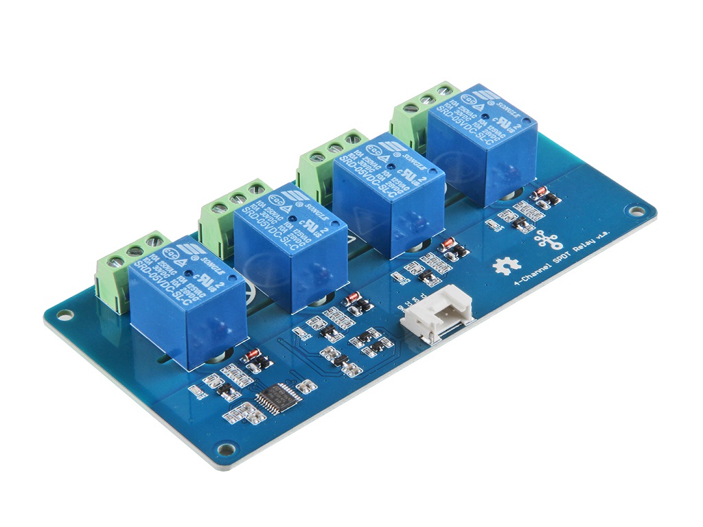
The Single Pole Double Throw SPDT relay is quite useful in certain applications because it has one common terminal and 2 contacts which are great for selecting between two options. The Grove - 4-Channel SPDT Relay has four single pole - double throw (SPDT) switches. It only requires low-voltage and low current signals to control those switches. Specifically, you can use 5V DC to control max.250V AC or 110V DC. The I2C address is changeable so that you can use multiple relay modules in the same project. The Grove - 4-Channel SPDT Relay has four single pole - double throw (SPDT) switches. It only requires low-voltage and low current signals to control those switches. Specifically, you can use 5V DC to control max.250V AC or 110V DC.
We use an on-board STM32F030F4P6 to control the channels separately. The command from Arduino or other boards is transmit via the I2C interface, the on-board STM32F030F4P6 will parse the command, so that you can control the switch you want.

Pre-reading
An introduction of What is a Grove Relay Module and How does a Relay work is strongly recommended reading ahead if you are not familiar with them. Please visit our blog below for detailed information:

Features
- High temperature resistant plastic shell
- High voltage load
- Low power consumption
- Long lasting
- Optional I2c address
- 0x00 ~ 0x7F
Specification
| Item | Value |
|---|---|
| Working voltage | 5V |
| Nominal Coil Current | 89.3mA |
| TUV Certification Load | 10A 250VAC/ 10A 30VDC |
| UL Certification Load | 10A 125VAC 28VDC |
| Max. Allowable Voltage | 250VAC/110VDC |
| Power Consumption | abt. 0.45W |
| Contact Resistance | 100mΩ Max. |
| Insulation Resistance | 100MΩ Min. (500VDC) |
| Max. ON/OFF Switching | 30 operation/min |
| Ambient Temperature | -40°C to +85°C |
| Operating Humidity | 45% to 85% r.h. |
| Contact Material | AgCdO |
| Input Interface | I^2^C |
| Default I^2^C Address | 0x11 or 0x12 |
| Available I^2^C Address | 0x00 ~ 0x7F |
| Output interface | 3 Pins DIP Female Screw Terminal-Green |
For the load parameter, we provide two sets of certification data. Actually, the max. laod is 10A 250VAC/10A 30VDC.
Applications
- Domestic appliance
- office machine
- Remote control TV receiver
- monitor display
- audio equipment high rushing current use application
Getting Started
Platforms Supported
| Arduino | Raspberry Pi | |||
|---|---|---|---|---|
The platforms mentioned above as supported is/are an indication of the module's software or theoritical compatibility. We only provide software library or code examples for Arduino platform in most cases. It is not possible to provide software library / demo code for all possible MCU platforms. Hence, users have to write their own software library.
Play With Arduino
Hardware
Materials required
| Seeeduino V4.2 | Base Shield | Grove - 4-Channel SPDT Relay |
|---|---|---|
 |  |  |
| Get One Now | Get One Now | Get One Now |
-
Please plug the USB cable gently, otherwise you may damage the port. Please use the USB cable with 4 wires inside, the 2 wires cable can't transfer data. If you are not sure about the wire you have, you can click here to buy.
-
Each Grove module comes with a Grove cable when you buy. In case you lose the Grove cable, you can click here to buy.
Hardware Overview
If we don't have Grove Base Shield, We also can directly connect this module to Seeeduino as below.
| Seeeduino | Grove - 4-Channel SPDT Relay |
|---|---|
| 5V | Red |
| GND | Black |
| SDA | White |
| SCL | Yellow |
Pin Map
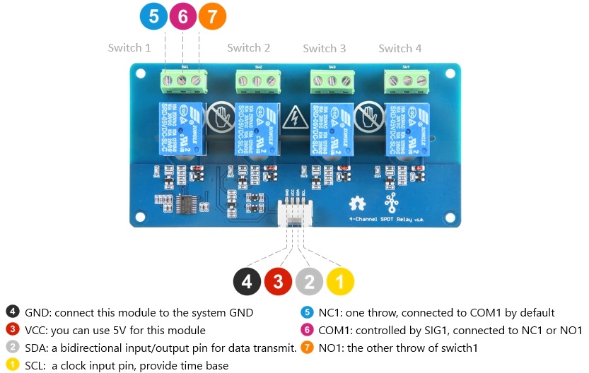
- The switch 1-4 have the same pin fuction, so for the other switches, you can refer to NC1/COM1/NO1.
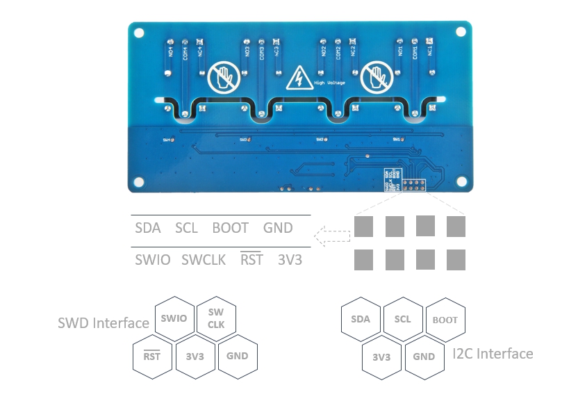
- On the back of the PCB, there are two interfaces: SWD and I^2^C. The SWD interface is used by default when programming firmware, if you want to use the I^2^C(actually work as the boot UART), you should set the BOOT High.
-
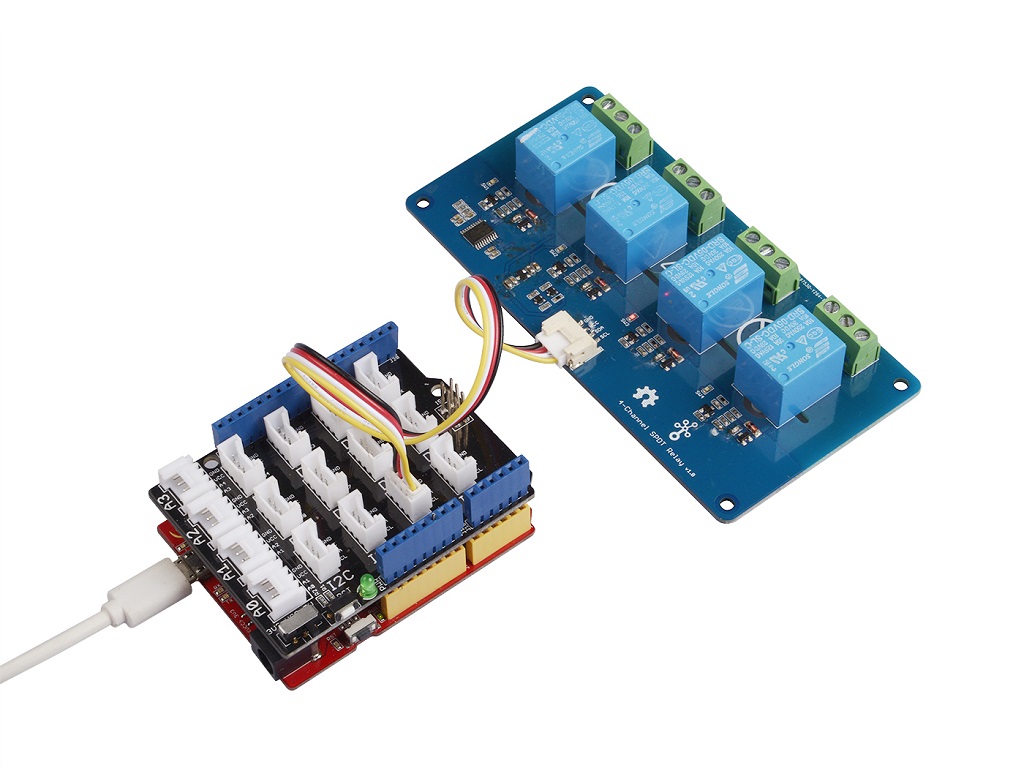
Step 1. Connect the Grove - 4-Channel SPDT Relay to the I^2^C port of the Base Shield.
-
Step 2. Plug Grove - Base Shield into Seeeduino.
-
Step 3. Connect Seeeduino to PC via a USB cable.
Software
If this is the first time you work with Arduino, we strongly recommend you to see Getting Started with Arduino before the start.
-
Step 1. Download the Multi_Channel_Relay_Arduino Library from Github.
-
Step 2. Refer to How to install library to install library for Arduino.
-
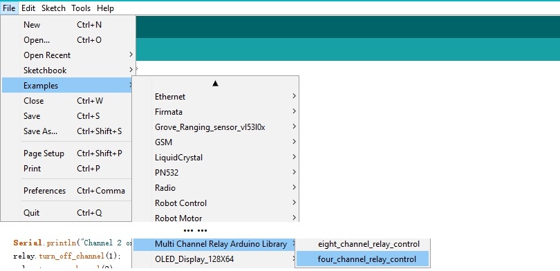
Step 3. Restart the Arduino IDE. Open example via the path: File --> Examples --> Multi Channel Relay Arduino Library --> four_channel_relay_control.
Or, you can just click the icon  in upper right corner of the code block to copy the following code into a new sketch in the Arduino IDE.
#include <multi_channel_relay.h>

Multi_Channel_Relay relay;

void setup()
{
  Serial.begin(9600);
  while(!Serial);

   /* Scan I2C device detect device address */
  uint8_t old_address = relay.scanI2CDevice();
  if((0x00 == old_address) || (0xff == old_address)) {
    while(1);
  }

  Serial.println("Start write address");
  relay.changeI2CAddress(old_address, 0x11);  /* Set I2C address and save to Flash */
  Serial.println("End write address");

  /* Read firmware  version */
  Serial.print("firmware version: ");
  Serial.print("0x");
  Serial.print(relay.getFirmwareVersion(), HEX);
  Serial.println();
}

void loop()
{

  /**
   *  channle: 8 7 6 5 4 3 2 1
   *  state: 0b00000000 -> 0x00  (all off)
   *  state: 0b11111111 -> 0xff  (all on)
  */

  /* Begin Controlling Relay */
  Serial.println("Channel 1 on");
  relay.turn_on_channel(1);
  delay(500);
  Serial.println("Channel 2 on");
  relay.turn_off_channel(1);
  relay.turn_on_channel(2);
  delay(500);
  Serial.println("Channel 3 on");
  relay.turn_off_channel(2);
  relay.turn_on_channel(3);
  delay(500);
  Serial.println("Channel 4 on");
  relay.turn_off_channel(3);
  relay.turn_on_channel(4);
  delay(500);
  relay.turn_off_channel(4);

  relay.channelCtrl(CHANNLE1_BIT |
                    CHANNLE2_BIT |
                    CHANNLE3_BIT |
                    CHANNLE4_BIT);
  Serial.print("Turn all channels on, State: ");
  Serial.println(relay.getChannelState(), BIN);

  delay(2000);

  relay.channelCtrl(CHANNLE1_BIT |
                    CHANNLE3_BIT);
  Serial.print("Turn 1 3 channels on, State: ");
  Serial.println(relay.getChannelState(), BIN);

  delay(2000);

  relay.channelCtrl(CHANNLE2_BIT |
                    CHANNLE4_BIT);
  Serial.print("Turn 2 4 channels on, State: ");
  Serial.println(relay.getChannelState(), BIN);

  delay(2000);


  relay.channelCtrl(0);
  Serial.print("Turn off all channels, State: ");
  Serial.println(relay.getChannelState(), BIN);

  delay(2000);
}
The library file may be updated. This code may not be applicable to the updated library file, so we recommend that you use the first methods.
-
Step 4. Upload the demo. If you do not know how to upload the code, please check How to upload code.
-
Step 5. Open the Serial Monitor of Arduino IDE by click Tool-> Serial Monitor. Or tap the ++ctrl+shift+m++ key at the same time.
If every thing goes well, you will get the result. Meanwhile, you will see the on-board LEDs alternately lit and extinguished.
Scanning...
I2C device found at address 0x12 !
Found 1 I2C devices
Start write address
End write address
firmware version: 0x1
Channel 1 on
Channel 2 on
Channel 3 on
Channel 4 on
Turn all channels on, State: 1111
Turn 1 3 channels on, State: 101
Turn 2 4 channels on, State: 1010
Turn off all channels, State: 0
Channel 1 on
Channel 2 on
The Grove - 4-Channel SPDT Relay will be working as below if everything goes well.
We do not add load in this demo, if you want to check how to add load, please check the Grove - 2-Channel SPDT Relay.
Function description
| Function | Description |
|---|---|
| changeI2CAddress(uint8_t old_addr, uint8_t new_addr) | change the device address,the old_addr is the current address; the new_addr is the address which you want to use. The new address can be successfully set only by entering the correct old address. |
| scanI2CDevice() | get the old_addr (current address) |
| getChannelState() | get the state of every channel, for instance "State: 1111", which means all the relay is turned on |
| getFirmwareVersion() | get the firmware version burn into the on board MCU |
| channelCtrl(uint8_t state) | to change all channels you picked immediately, the state parameter list: CHANNLE1_BITor 0x01 CHANNLE2_BIT or 0x02 CHANNLE3_BIT or 0x04 CHANNLE4_BIT or 0x08 e.g. channelCtrl(CHANNLE2_BIT|CHANNLE3_BIT),will turn on the channel 2,channel 3 channelCtrl(01|02|08), will turn on the channel 1,channel 2 and channel 4. channelCtrl(0), will turn off all the channels. |
| turn_on_channel(uint8_t channel) | to turn on the single channel. e.g. turn_on_channel(3), will turn on the channel 3 |
| turn_off_channel(uint8_t channel) | to turn off the single channel. e.g. turn_off_channel(3), will turn off the channel 3 |
In case you want to change the address, you need to set the address before use. For example, we want to change it into 0x2f. We can use the following code.
#include <multi_channel_relay.h>

Multi_Channel_Relay relay;

void setup()
{
  Serial.begin(9600);
  while(!Serial);

   /* Scan I2C device detect device address */
  uint8_t old_address = relay. ;
  if((0x00 == old_address) || (0xff == old_address)) {
    while(1);
  }

  Serial.println("Start write address");
  relay.changeI2CAddress(old_address,0x2f);  /* Set I2C address as 0x2f and save it to the EEPRom */
  Serial.println("End write address");

  /* Read firmware  version */
  Serial.print("firmware version: ");
  Serial.print("0x");
  Serial.print(relay.getFirmwareVersion(), HEX);
  Serial.println();
}
FAQ
Q1: How to burn the firmware?
A1: We recommend you use the J-Link burner and the WSD interface to burn the firmware.
You can download the firmware here:
We recommed you use the J-flash for the software:

Schematic Online Viewer
Because ST32 series chips are out of stock globally, prices have increased several times and there is no clear delivery date. We have no choice but to switch to the MM32 chip. The specific replacement models are as follows: STM32F030F4P6TR is replaced by MM32F031F6P6. After the chip is replaced, the product functions, features, usage methods and codes remain unchanged. It should be noted that the firmware version has changed, and the factory firmware has been adjusted according to different chips. If you need to re-burn the firmware, please download the firmware corresponding to the chip.
Resources
- [Zip] Grove-4-Channel SPDT Relay eagle files
- [Bin] STM32F030F4P6TR-Firmware
- [Bin] MM32F031F6P6-Firmware
- [PDF] Datasheet of SRD 05VDC-SL-C Relay
- [PDF] Datasheet of S9013
- [PDF] Datasheet of STM32
- [PDF] MM32F031F6P6_Datasheet.pdf
Project
This is the introduction Video of this product, simple demos, you can have a try.
Home Automation and Monitoring: An RSL10 Sense DB based system that can monitor and control the temperature, humidity, and light intensity by Smartphone app and Alexa.
Grove - 4-Channel SPDT Relay: Hey Seeekers!!! This is the second week of our #newproductsTuesday segment. There will be a product showcase of our new Grove - 4-Channel SPDT Relay in this video and a cool interesting demo as well.
Tech Support & Product Discussion
Thank you for choosing our products! We are here to provide you with different support to ensure that your experience with our products is as smooth as possible. We offer several communication channels to cater to different preferences and needs.