Grove - Voltage Divider
The Grove – Voltage Divider provides an interface for measuring external voltage, eliminating the need to connect a resistance to input interface. Besides, the voltage gain can select by dial switch. They are easy to use.

Feature
- Extern Voltage Interface and Grove Interface
- Easy to use
- Can adjust the gain
More details about Grove modules please refer Grove System
Specification
| Item | Min | Typical | Max | Unit |
|---|---|---|---|---|
| Working Voltage | 4.7 | 5.0 | 5.3 | VDC |
| Measurement Accuracy | / | <=1 | / | % |
| Extern Voltage Range (select 3) | 0.3 | / | 12.9 | V |
| Extern Voltage Range (Select 10) | 1.0 | / | 43 | V |
| Dimension | / | 24X20 | / | mm |
Platforms Supported
| Arduino | Raspberry Pi | BeagleBone | Wio | LinkIt ONE |
|---|---|---|---|---|
The platforms mentioned above as supported is/are an indication of the module's software or theoritical compatibility. We only provide software library or code examples for Arduino platform in most cases. It is not possible to provide software library / demo code for all possible MCU platforms. Hence, users have to write their own software library.
Getting Started
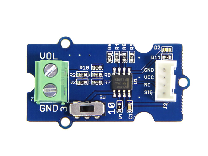
When measuring the external voltage, connect the external voltage to J1 and then connect the on-board Grove connector to analog port of Arduino/Seeeduino:
- Connect the module to A0 port of Grove - Base Shield with a universal Grove Cable.
- Connect Grove - Base Shield to Arduino/Seeeduino.
In order to test the precision of this module, I tested some voltage inputs and get the following data:
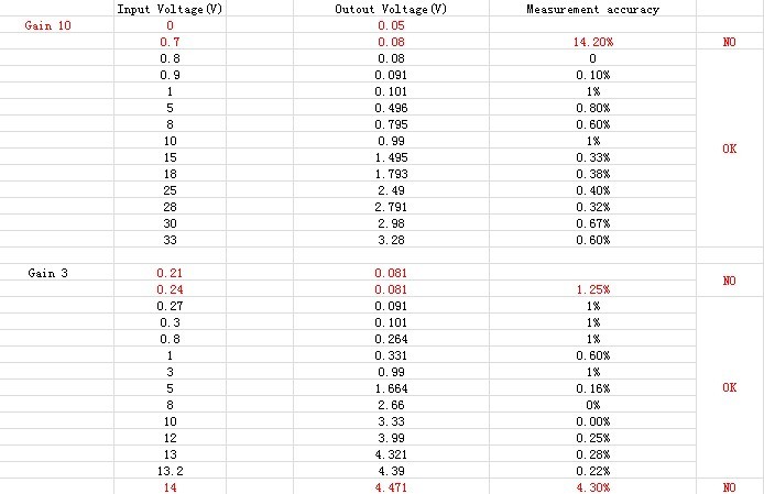
- As you can see, when the inputs were in the measuring range, the voltage divider has a high accuracy(<1%, that i marked an "OK"). But as the inputs were not in the range, the accuracy gets low(i marked a "NO") Please see Specification about the specific measurement range.
And When voltage divider output voltage is higher than VCC (The Grove Operating Voltage and reference of analog read), an indicator will light up to show you the error.
- Using the serial monitor of Arduino, you can measure the input voltage value. Demo code as show below:
void setup()
{
    Serial.begin(9600);
}

void loop()
{
    long  sensorValue=analogRead(A0);
    long  sum=0;
    for(int i=0;i<1000;i++)
    {
        sum=sensorValue+sum;
        sensorValue=analogRead(A0);
        delay(2);
    }
    sum=sum/1000;

    Serial.print("if you set the Gain to 10,the input voltage:");
    Serial.println(10*sum*4980/1023.00);

    Serial.print("if you set the Gain to 3,the input voltage:");
    Serial.println(3*sum*4980/1023.00);

    delay(1000);
}
Play with Codecraft
Hardware
Step 1. Connect a Grove - Voltage Divider to port A0 of a Base Shield.
Step 2. Plug the Base Shield to your Seeeduino/Arduino.
Step 3. Link Seeeduino/Arduino to your PC via an USB cable.
Software
Step 1. Open Codecraft, add Arduino support, and drag a main procedure to working area.
If this is your first time using Codecraft, see also Guide for Codecraft using Arduino.
Step 2. Drag blocks as picture below or open the cdc file which can be downloaded at the end of this page.

Upload the program to your Arduino/Seeeduino.
When the code finishes uploaded, you will see the voltage in the Serial Monitor.
Schematic Online Viewer
Resource
Tech Support & Product Discussion
Thank you for choosing our products! We are here to provide you with different support to ensure that your experience with our products is as smooth as possible. We offer several communication channels to cater to different preferences and needs.