Overview
In this wiki, we are introducing how to add more Grove modules in to SenseCAP S2110 Sensor Builder and list all the supported ones.
Add Grove - ±5A DC/AC Current Sensor (ACS70331) to the builder and applying
1. Build new libraries using GitHub source code
The contents here are on the GitHub where we maintain the code.
-
Step 1: Add a
sensorNew.hppfile to thesrc\sensorfolder for the new sensor. -
Step 2: Define the sensor class and implement the
init()andsample()functions.
The sensor class should inherits from the sensorClass class, and implement the init() and sample() functions.
The init() function is used to initialize the sensor, and than returns a register offset value for Modbus communication.
The sample() function is used to read the sensor data, returns true when the data is valid, and returns false when the data is invalid.
- Step 3: Include the
sensorNEW.hppfile and call it.
Add line #include "sensorNew.hpp" to the src\sensor\sensorBuilder.hpp file.
In the setup() function of the sensorBuilder.ino file, create the new sensor class object and call the SensorBuilder.addSensor() function with it as an argument.
Refer to the following code :
void setup()
{
  Serial.begin(9600);
  SensorBuilder.check_grove();

  /* sensor list */
  sensorUltrasonic *ultrasonic = new sensorUltrasonic();
  SensorBuilder.addSensor(ultrasonic);

  // add new sensor to sensor list
  sensorNew *newSensor = new sensorNew();
  SensorBuilder.addSensor(newSensor);

  SensorBuilder.begin();
}
The Modbus register address for the new sensor will start from 0x0034, the register bit width for each measurement value is 32, so the register address offset between two adjacent measurement values is 2.
2. Knowledge of Modbus Register Table
Modbus register addresses 0x0000 to 0x0003 are reserved for storing module system information, where 0x0000 is the modbus address with a default value of 1 and a maximum value of 247, 0x0001 is the serial port baud rate with a default value of 96 (corresponding to 9600), and 0x0002 to 0x0003 are for software version.
| Grove Sensor Name | Register Name | Register Address (Hexadecimal) | Register Address (Decimal) |
|---|---|---|---|
| Grove - CO2 & Temperature & Humidity Sensor (SCD41) | Temperature | 0x0004 | 04 |
| Humidity | 0x0006 | 06 | |
| CO2 | 0x0008 | 08 | |
| Grove - Light Sensor v1.2 | Light | 0x000A | 10 |
| Grove - Flame Sensor | Flame | 0x000C | 12 |
| Grove - Oxygen Sensor (MIX8410) | Oxygen | 0x000E | 14 |
| Grove - Sunlight sensor (SI1151) | Light Intensity | 0x0010 | 16 |
| Visible Light | 0x0012 | 18 | |
| UV | 0x0014 | 20 | |
| Grove Temperature and Barometer Sensor (BMP280) | Barometric Temperature | 0x0016 | 22 |
| Atmospheric Pressure | 0x0018 | 24 | |
| Height | 0x001A | 26 | |
| Grove - Temperature Humidity Pressure Gas Sensor(BME680) | Temperature | 0x001C | 28 |
| Atmospheric Pressure | 0x001E | 30 | |
| Humidity | 0x0020 | 32 | |
| Air Quality(VOC) | 0x0022 | 34 | |
| Grove - Gas Sensor V2(Multichannel) | N02 | 0x0024 | 36 |
| C2H50H | 0x0026 | 38 | |
| VOC | 0x0028 | 40 | |
| CO | 0x002A | 42 | |
| Grove - UV Sensor | UV Intensity | 0x002C | 44 |
| Grove - Turbidity Sensor Meter V1.0 | Turbidity | 0x002E | 46 |
| Grove - TDS Sensor | TDS | 0x0030 | 48 |
| Grove - Ultrasonic Ranger | Distance | 0x0032 | 50 |
3. Knowledge of Hardware Connection
Connect the SIG (signal) pin of the sensor to one of the analog pins of the any microcontroller, supply 5V-3.3V to VCC and GND to Ground of the microcontroller.
The Grove sensor comes with a potentiometer mounted on it, that allows the user to fine tune with the gain, making adjustable to fit different input voltages. Its helps change sensor's sensitivity.

4. From steps above, we can have the library for Grove AC sensor:
Stick to the steps above, we have the library for applying Grove AC sensor.
#ifndef _SENSOR_AC_H
#define _SENSOR_AC_H

#include "sensorClass.hpp"

#define AC_ADC_PIN A2
#define ADC_BITS 12
#define ADC_COUNTS (1<<ADC_BITS)

class sensorAC : public sensorClass
{
  public:
  sensorAC(): sensorClass("AC"){};
  ~sensorAC(){};

  uint16_t init(uint16_t reg, bool i2c_available);
  bool connected();
  bool sample();

  enum
  {
    AC = 0,
    MAX
  };
  private:
  	double voltCal = 523.56;
  	double phaseCal = 1.7;
  	unsigned int cycles = 20;
  	unsigned int timeout = 2000;
  	int SupplyVoltage = 3300;
  	int sampleV;
  	double lastFilteredV,filteredV;
  	double offsetV = ADC_COUNTS >> 1;
  	double phaseShiftedV;
  	double sqV,sumV;
  	int startV;
  	boolean lastVCross,checkVCross;
};

uint16_t sensorAC::init(uint16_t reg, bool i2c_available){
  uint16_t t_reg = reg;

  for (uint16_t i = 0; i < sensorAC::MAX; i++)
    {
        sensorClass::reg_t value;
        value.addr = t_reg;
        value.type = sensorClass::regType_t::REG_TYPE_S32_ABCD;
        value.value.s32 = 0;
        t_reg += sensorClass::valueLength(value.type);
        m_valueVector.emplace_back(value);
    }

    _connected = i2c_available ? false : true;
    //_connected = true;
    return t_reg - reg;
}

bool sensorAC::sample()
{

  GROVE_SWITCH_ADC;
  pinMode(AC_ADC_PIN, INPUT);

  unsigned int crossCount = 0;
  unsigned int numberOfSamples = 0;

  unsigned long start = millis();

  while(1){
	int startV = analogRead(AC_ADC_PIN);
	if((startV<(ADC_COUNTS*0.51)) && (startV>(ADC_COUNTS*0.49)))
		break;
	if((millis()-start)>timeout)
		break;
  }

  start = millis();

  while((crossCount<cycles) && ((millis()-start)<timeout))
  {
  	numberOfSamples++;
  	lastFilteredV = filteredV;

  	sampleV = analogRead(AC_ADC_PIN);
  	offsetV = offsetV + ((sampleV - offsetV)/ADC_COUNTS);
  	filteredV = sampleV - offsetV;

  	sqV = filteredV * filteredV;
  	sumV += sqV;

  	phaseShiftedV = lastFilteredV + phaseCal * (filteredV - lastFilteredV);

  	lastVCross = checkVCross;
  	if(sampleV>startV)
  		checkVCross = true;
  	else
  		checkVCross = false;
  	if(numberOfSamples == 1)
  		lastVCross = checkVCross;
  	if(lastVCross !=checkVCross)
  		crossCount++;
  }

  double V_RATIO = voltCal * ((SupplyVoltage/1000.0)/(ADC_COUNTS));
  float value = V_RATIO * sqrt(sumV/numberOfSamples);
  m_valueVector[AC].value.s32 = value * SCALE;
  //Serial.println(value);
  sumV = 0;

  return true;
}

bool sensorAC::connected()
{
  return _connected;
}

#endif
5. Using Arduino to program to test first
The program takes a few parameters, that need to be initialized before running the program. This ensure that the program is running correctly with the sensor and to get accurate values.
First flash the program into the microcontroller, then calibrate the parameters to fit the readings.
#define AC_ADC_PIN A2				//here pin A2 is used
#define ADC_BITS 12					//depends on microcontroller to microcontroller
#define Calibration_Value 523.56	//depends on the calibration result
#define Phase_Shift 1.7 			//depends on the calibration result

void setup() {
  Serial.begin(115200);
  pinMode(AC_ADC_PIN, INPUT);
}

int ADC_COUNTS = (1<<ADC_BITS);
double voltCal = Calibration_Value;
double phaseCal = Phase_Shift;
unsigned int cycles = 10;			//Number of AC Cycles you want to measure
unsigned int timeout = 500;			//Timeout
int SupplyVoltage = 3300;
int sampleV;
double lastFilteredV,filteredV;
double offsetV = ADC_COUNTS >> 1;
double phaseShiftedV;
double sqV,sumV;
int startV;
boolean lastVCross,checkVCross;

void loop() {
  unsigned int crossCount = 0;
  unsigned int numberOfSamples = 0;

  unsigned long start = millis();

  while(1){
  int startV = analogRead(AC_ADC_PIN);
  if((startV<(ADC_COUNTS*0.51)) && (startV>(ADC_COUNTS*0.49)))
    break;
  if((millis()-start)>timeout)
    break;
  }

  start = millis();

  while((crossCount<cycles) && ((millis()-start)<timeout))
  {
    numberOfSamples++;
    lastFilteredV = filteredV;

    sampleV = analogRead(AC_ADC_PIN);
    offsetV = offsetV + ((sampleV - offsetV)/ADC_COUNTS);
    filteredV = sampleV - offsetV;

    sqV = filteredV * filteredV;
    sumV += sqV;

    phaseShiftedV = lastFilteredV + phaseCal * (filteredV - lastFilteredV);

    lastVCross = checkVCross;
    if(sampleV>startV)
      checkVCross = true;
    else
      checkVCross = false;
    if(numberOfSamples == 1)
      lastVCross = checkVCross;
    if(lastVCross !=checkVCross)
      crossCount++;
  }

  double V_RATIO = voltCal * ((SupplyVoltage/1000.0)/(ADC_COUNTS));
  float value = V_RATIO * sqrt(sumV/numberOfSamples);
  Serial.println(value);
  sumV = 0;

}
6. Get Calibration value
Initially the Analog pin is set to the A2 pin, could be changed according to your requirement, using AC_ADC_PIN parameter. Calibration_Value and Phase_Shift value, need to be changed every time you change the voltage source as the AC voltage varies from country to country or sometimes even socket to socket.
The program outputs the sensor value onto the serial monitor. One can also open the serial plotter to view the voltage vs time graph.
- Step 1: Take the multimeter and measure the AC voltage and note it down.
- Step 2: Similarly note the voltage shown in the serial monitor.
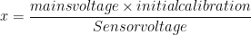
Here in my case, the reading from the multimeter is 220V RMS voltage, while the sensor shows 718.87V on the serial monitor, in order to get an accurate calibration value, we need to do simple math, using the following formula.
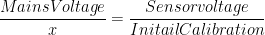
- Step 3: Find the value of x and replace it with Calibration_Value in the program and flash the program to the microcontroller.
Reference
- You can refer the Grove AC-Voltage Sensor Library for more information.
- More details on the calculation can be found here
The list of supported Grove modules for SenseCAP S2110 Sensor Builder
Currently, SenseCAP S2110 Sensor Builder supports the following Grove modules out-of-the-box to communicate with SenseCAP Data Logger and send the sensor data to the SenseCAP platform via LoRa.
- Grove - Temperature and Barometer Sensor (BMP280)
- Grove - Oxygen Sensor (MIX8410)
- Grove - CO2 & Temperature & Humidity Sensor - SCD41
- Grove - Sunlight Sensor - SI1151
- Grove - Light Sensor v1.2 - LS06-S phototransistor
- Grove - Flame Sensor
- Grove - Gas Sensor(BME680)
- Grove - Multichannel Gas Sensor v2
- Grove - TDS Sensor/Meter For Water Quality (Total Dissolved Solids)
- Grove - UV Sensor
- Grove - Ultrasonic Distance Sensor
- Grove - Turbidity Sensor
- Grove - Lightning Sensor
- Grove - ±5A DC/AC Current Sensor (ACS70331)
✨ Contributor Project
- This project is supported by the Seeed Studio Contributor Project.
- Thanks Mohammed Adnan Khan's efforts and your work will be exhibited.
Tech Support & Product Discussion
Thank you for choosing our products! We are here to provide you with different support to ensure that your experience with our products is as smooth as possible. We offer several communication channels to cater to different preferences and needs.