Getting Started with SenseCAP S2120 8-in-1 LoRaWAN Weather Sensor
Pre-Installation
Diagram
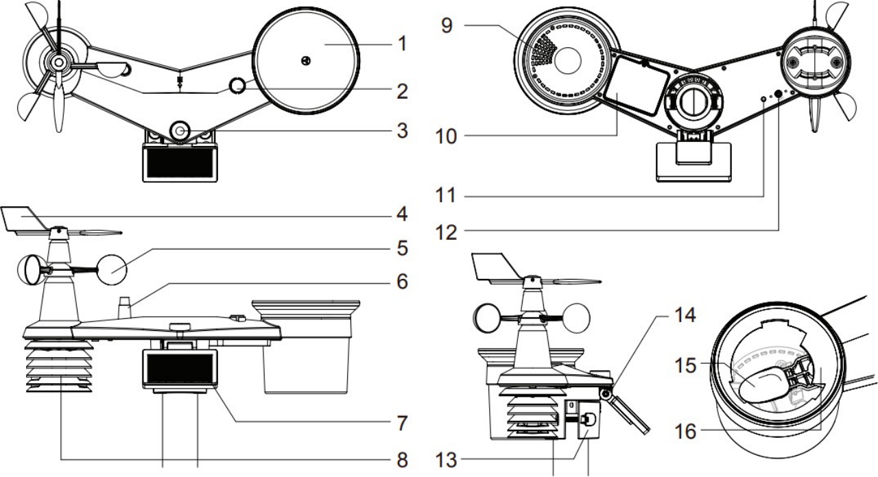
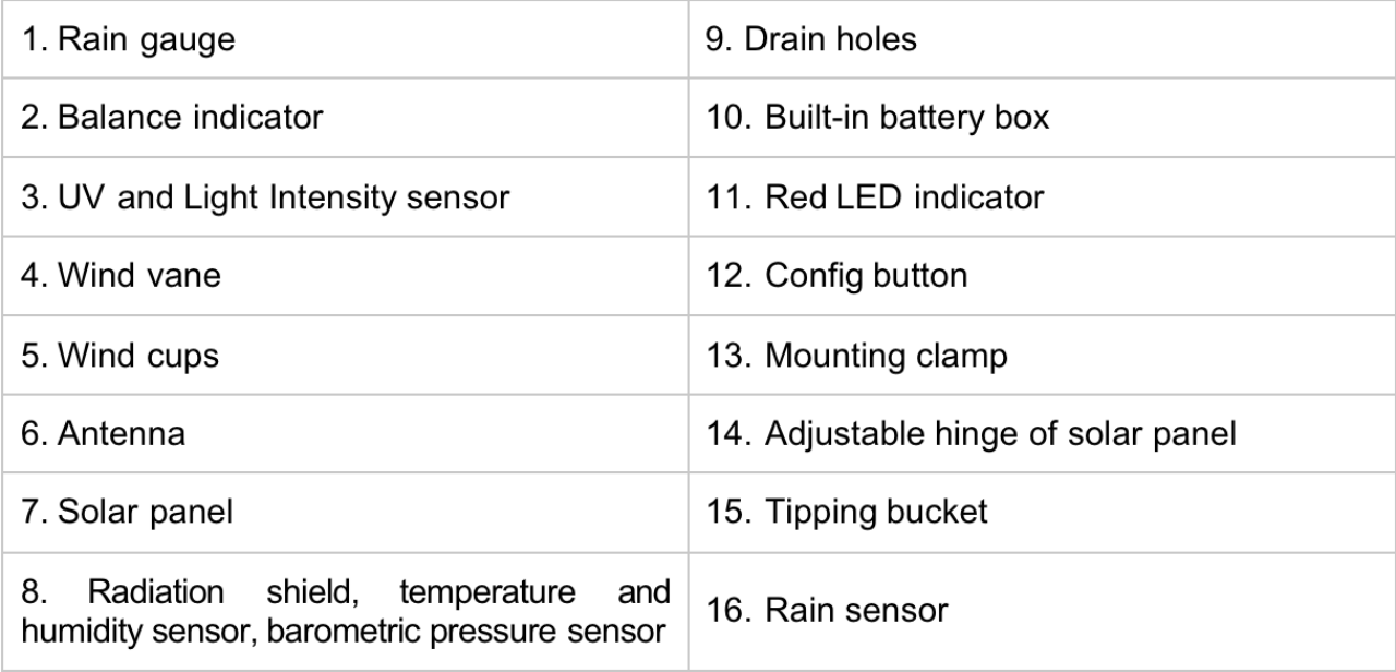
Install the Rain Gauge
Install the rain gauge funnel and rotate clockwise to lock the funnel to the weather station.
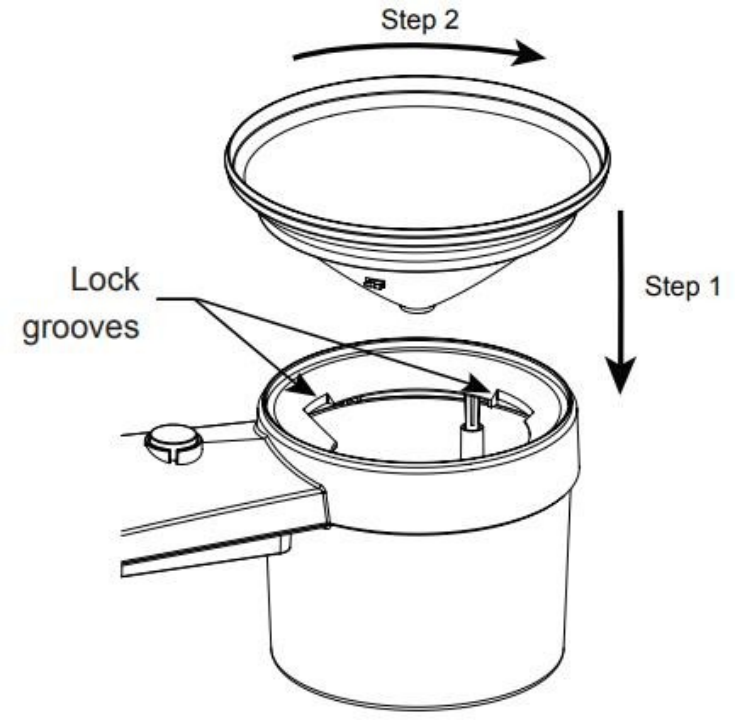
Power Supply Mode
Weather stations do not contain batteries, so additional batteries are required.
The sensor is powered by a combination of solar panels and batteries. When the solar panels are working, the device is powered by the solar panels; When solar energy is low, it is powered by batteries.
Different types of batteries affect the operating temperature range of the sensor. In addition, the different number of batteries determines the battery life of the sensor.
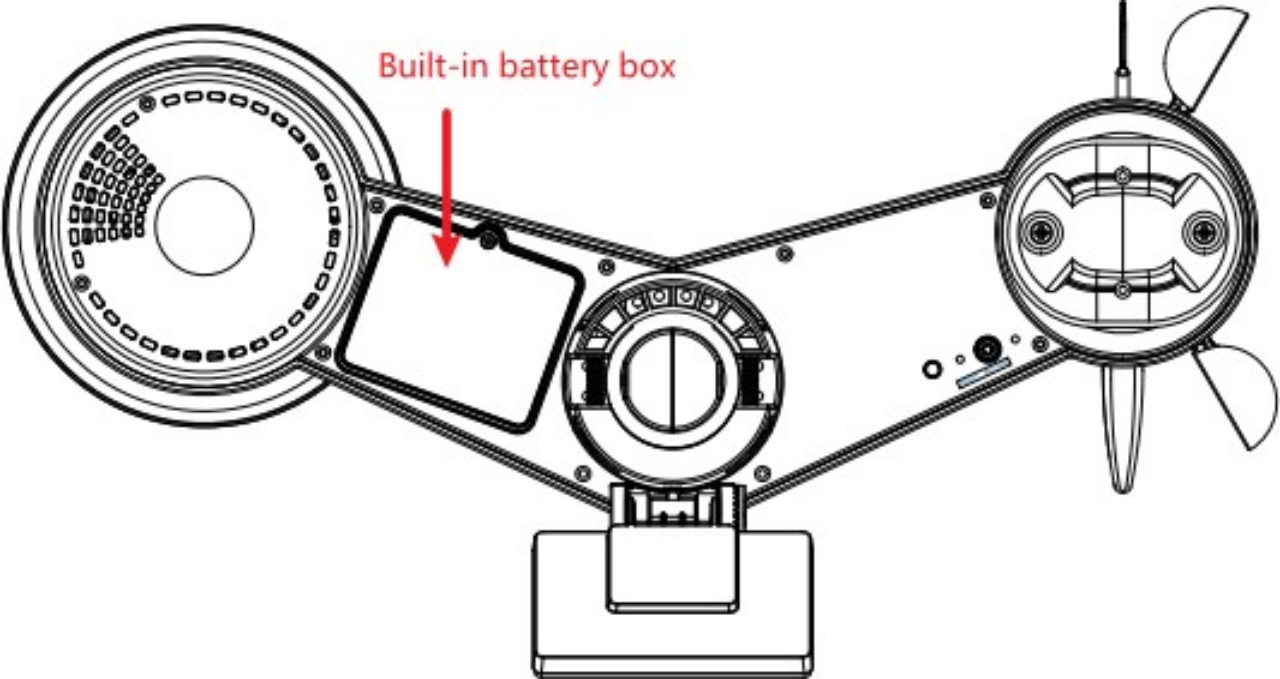
Option 1: Install the battery with a built-in box
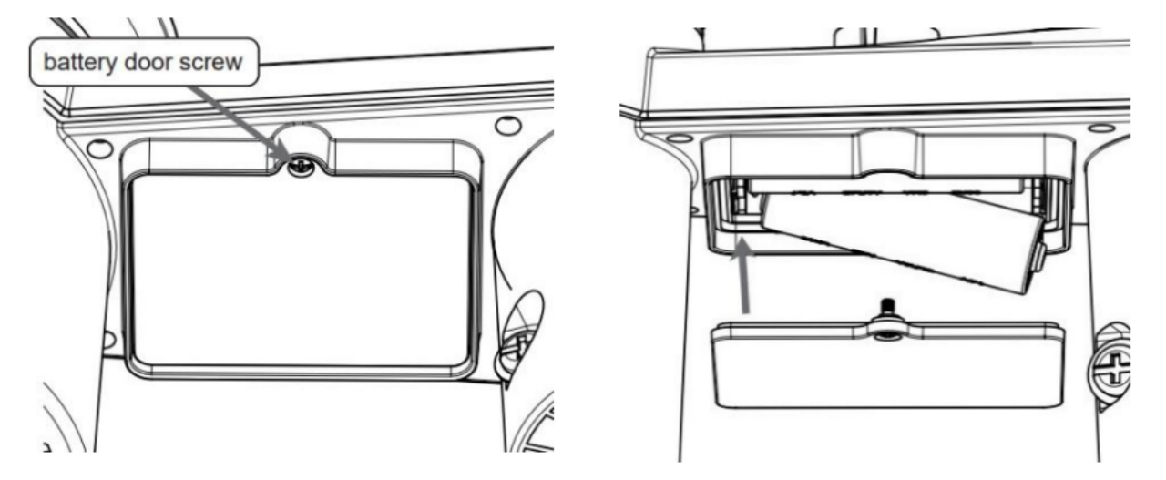
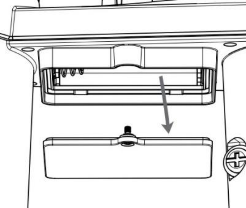
- Step 1: Unscrew the battery door at the bottom of the weather station.
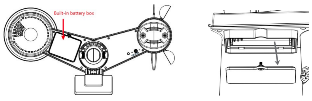
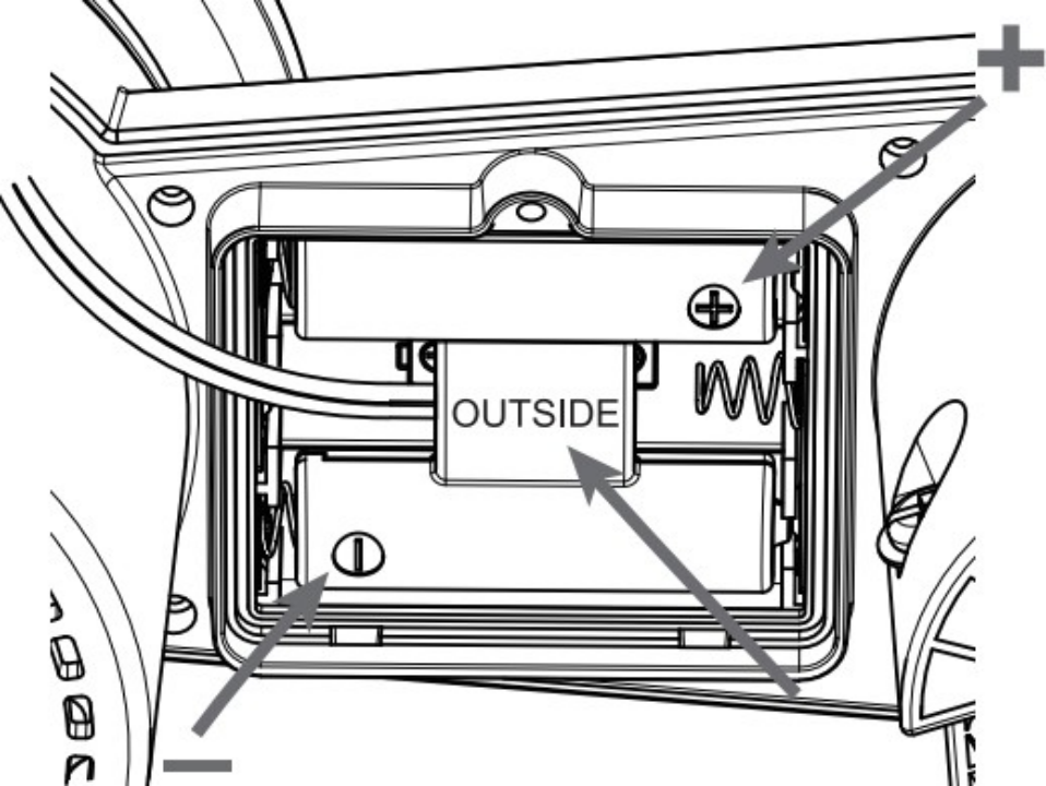
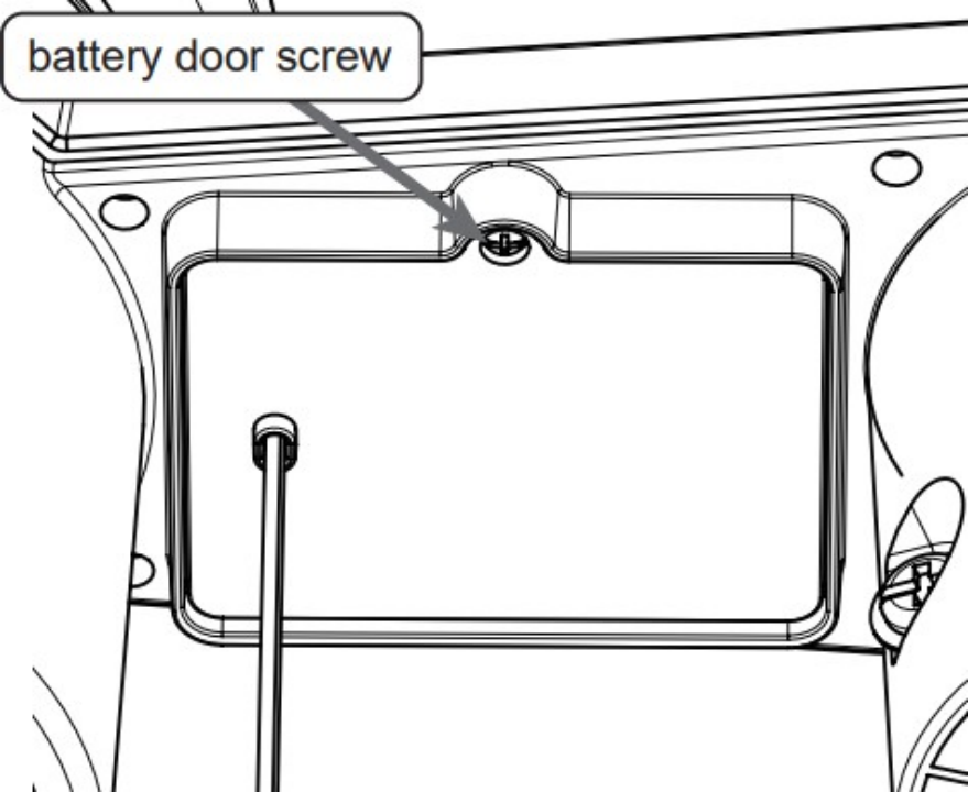
- Step 2: Insert the 3 AA batteries according to the +/- polarity indicated. Then close the battery door. Tighten the battery door screw. Once the installation is completed, the red LED indicator at the bottom of the weather station will be flashing.
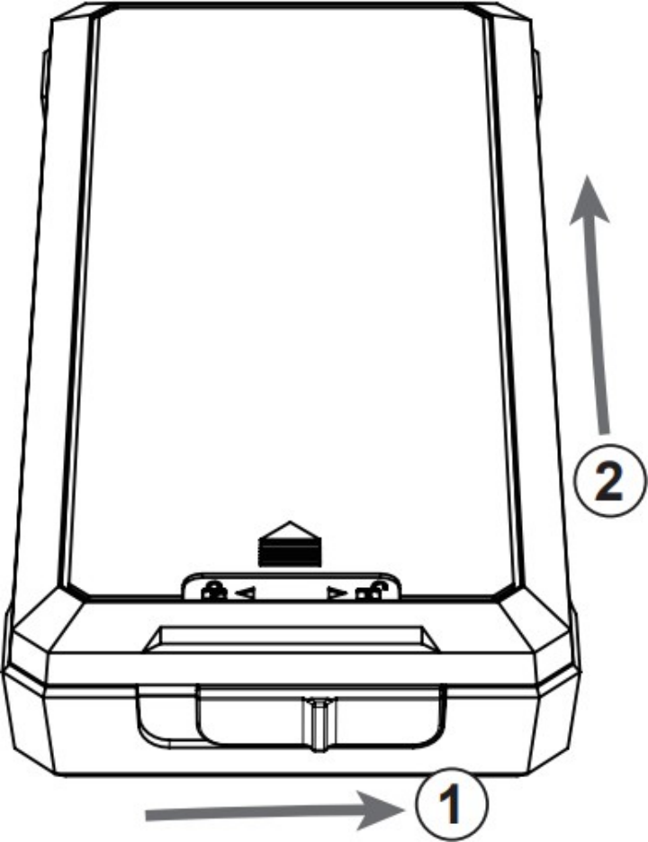
Option 2: Install the battery with an external box
- Step 1: Slide the battery box lock switch to unlock position. Push to open the battery box door according to the arrow direction.
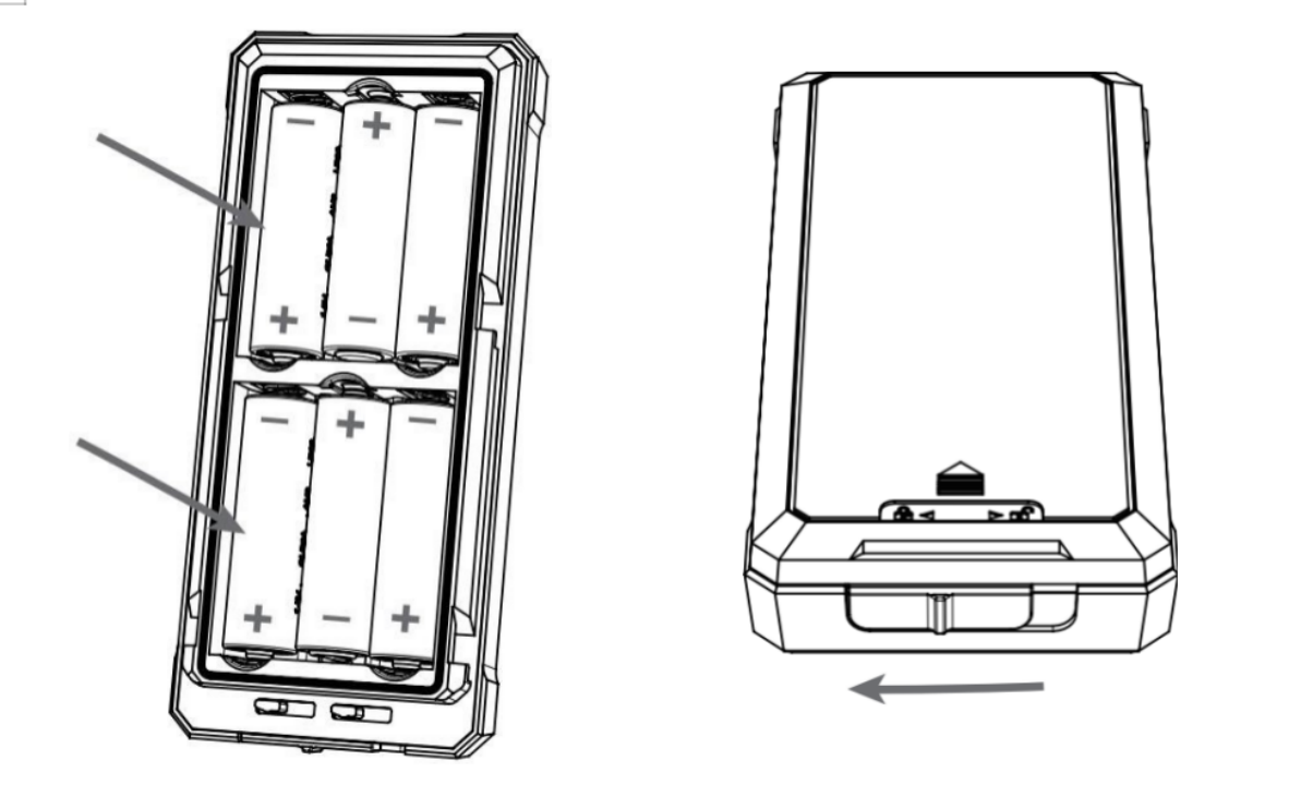
- Step 2: Insert the 6 AA batteries according to the +/- polarity indicated. And then place and lock the battery box door.
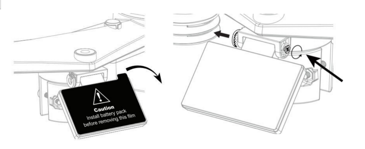
- Step 3: Unscrew the battery door at the bottom the of weather station.
- Step 4: Insert the dummy battery into the battery compartment, make sure the "OUTSIDE" marking faces outside and the +/- polarity is in the correct orientation.
Step 5: Replace the battery door which comes along with the external battery box, then tighten the battery door screw. Once the installation is completed, the red LED indicator at the bottom of the weather station will be flashing.
If the dummy battery is not installed in the correct orientation, the battery power connection will be failure and the LED indicator will not be flashing.
- Step 6: Use the cable ties to mount the battery box onto the mounting pole.
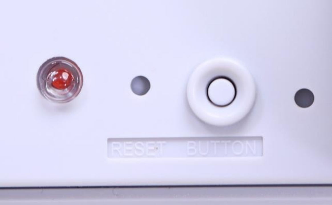
Indicator Status
At the bottom of the weather station are buttons and indicators:
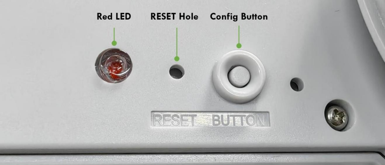
You can refer to the LED indicator for the Sensor for its working status. Please see the status explanations in the chart below:
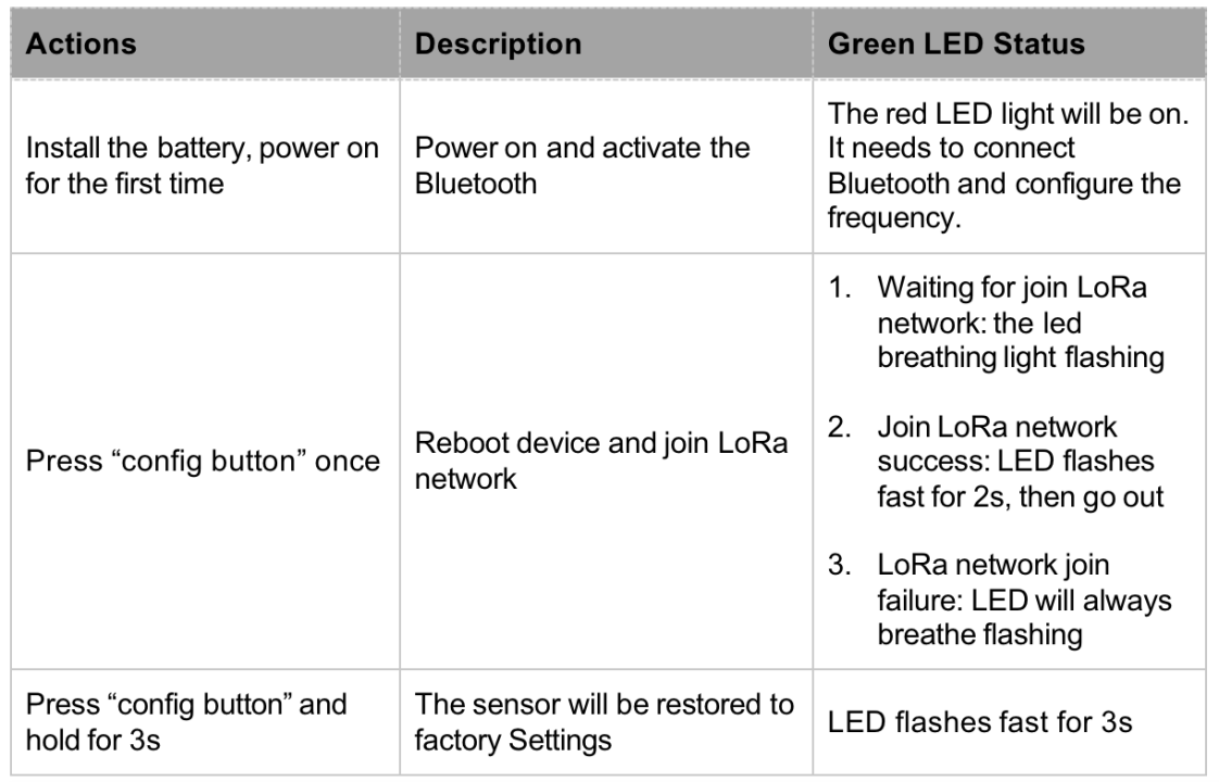
After the battery is installed for the first time, you must connect the Bluetooth and configure the frequency to join the LoRaWAN network and work normally. If the frequency is not set, the red LED is steadily on.
Connect to SenseCAP Mate App
Step 1: Download the App
As a tool, SenseCAP Mate App is used to config LoRa parameters, set intervals, bind devices to your account, and check device basic information.

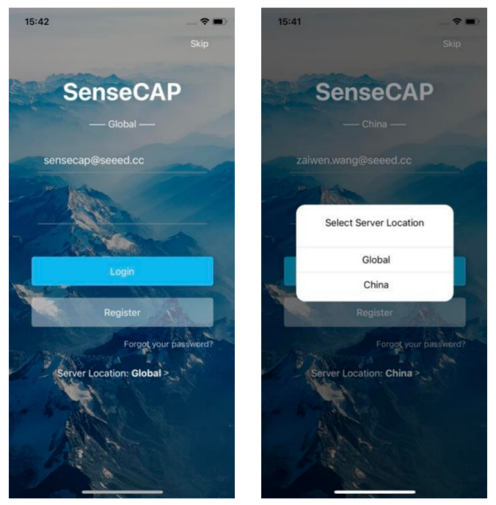
Step 2: Create a New Account
SenseCAP Mate supports device configuration and remote management. To use the SenseCAP Portal platform and other functions, please register an account.
SenseCAP Mate supports offline functionality, and you can opt out of an account if you only use the configuration sensor. Just click Skip.
Please select Global of Server Location.
You can also create an account via the SenseCAP Portal: http://sensecap.seeed.cc
If you can't find the email, it may be automatically identified as "spam" and put in the "trash can".
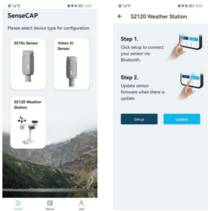
Step 3: Connect to Sensor to App
After the battery is installed, the red LED will be steady on. Also, activate Bluetooth.
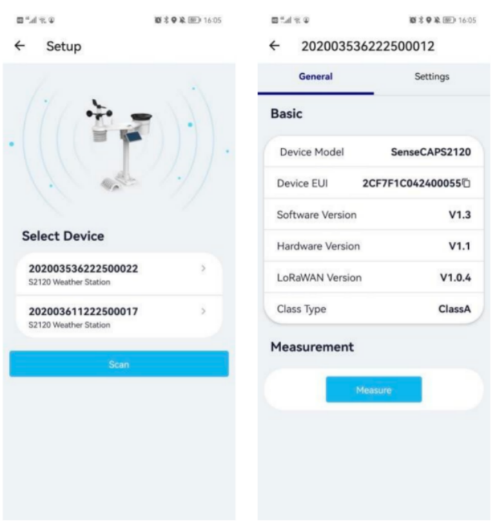
Please select "S2120 Weather Station". Please click the "Setup" button to turn on Bluetooth and click "Scan" to start scanning the sensor's Bluetooth.
Enter the pairing password. The default password is 000000.
Select the Sensor by BT ID (BT ID is on the bottom label of the sensor). Then, the basic information of the sensor will be displayed after entering.
Step 4: Configure parameters through the App
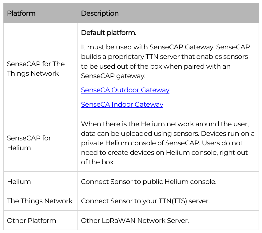
- Select the Platform
S2120 weather stations are manufactured to support universal frequency plan from 863MHz~928MHz in one SKU. That is to say, every single device can support 7 frequency plans.
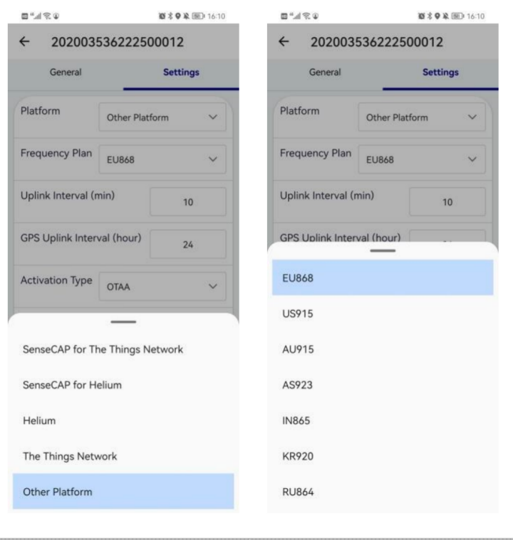
- Select the Frequency
Different countries and LoRaWAN network servers use different frequency plans.
- For Helium network, please refer to:
https://docs.helium.com/lorawan-on-helium/frequency-plans
- For The Things Network, please refer to:
https://www.thethingsnetwork.org/docs/lorawan/frequency-plans/
- When using the SenseCAP platform, the EUI, APP EUI and APP Key are fixed and are the same as the sensor label.
- When the sensor is selected to be used with a public platform such as Helium or TTN, the EUI will not change, and the sensor will generate a new fixed App EUI and App Key for network access.
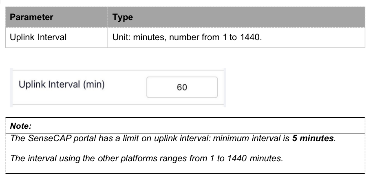
- Set the Interval
The working mode of device: wake up the device every interval and collect measurement values and upload them through LoRa. For example, the device collects and uploads data every 60 minutes by default.
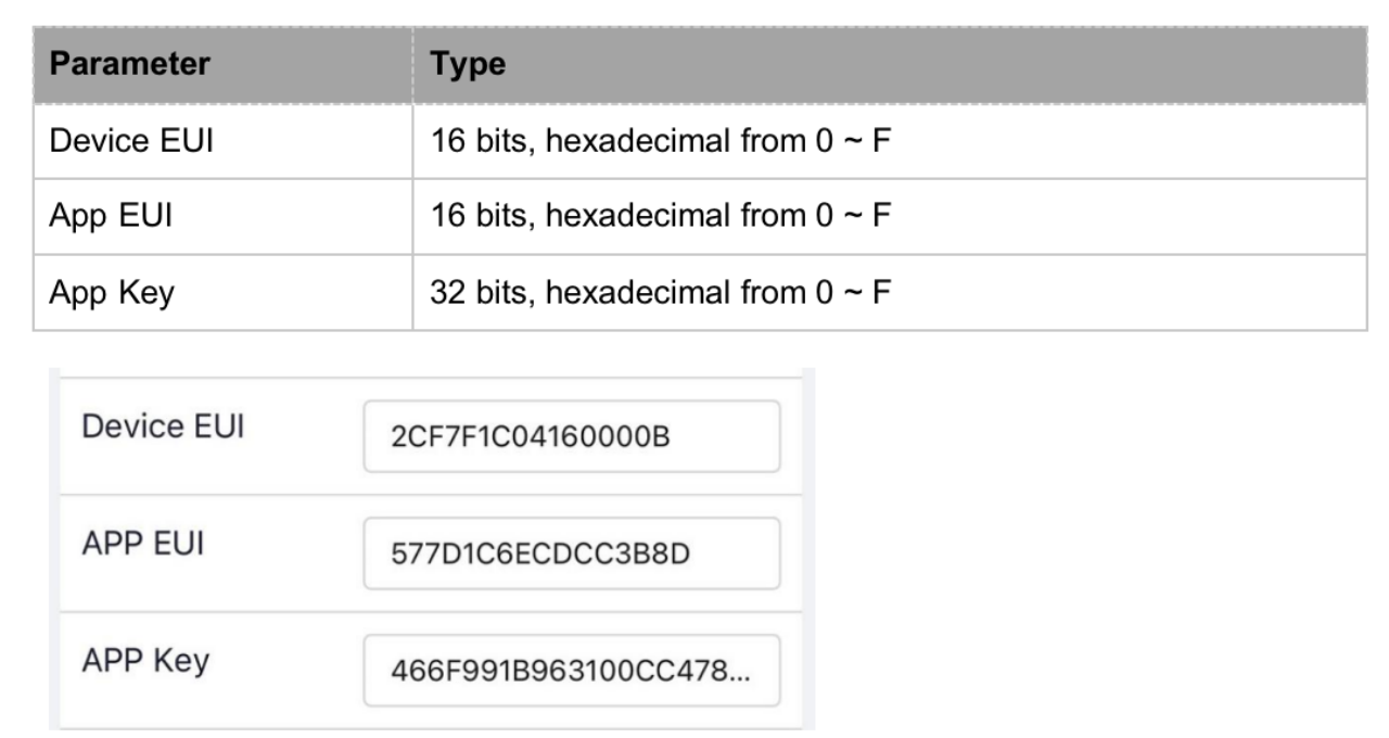
- Set the EUI and Key
The device uses OTAA to join the LoRaWAN network by default. So, it can set the device EUI and App EUI.
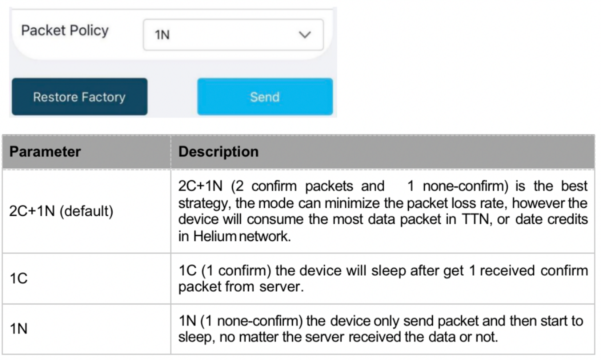
- Set the Packet Policy
The sensor uplink packet strategy has three modes.
- Set the Activation Type
The sensor supports two network access modes, OTAA by default.
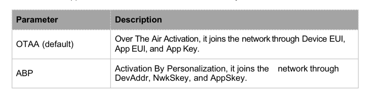
When using ABP mode, you need to configure the following information:
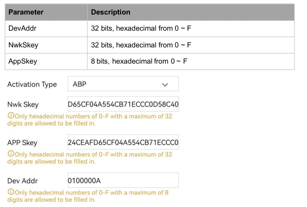
The factory defaults to a fixed value.
- Restore the Factory Setting
When selecting the SenseCAP platform, you must use the fixed EUI/App EUI/App Key. Therefore, you need to restore the factory Settings before switching back to the SenseCAP platform from other platforms.

When we make a mistake or want to reset everything, we can click the button. The device will be restored to the factory's default configuration.
Connect to the SenseCAP Portal
The main function of the SenseCAP Portal is to manage SenseCAP devices and to store data. It is built on Azure, a secure and reliable cloud service from Microsoft. You can apply for an account and bind all devices to this account. SenseCAP provides the web portal and API. The web portal includes Dashboard, Device Management, Data Management, and Access Key Management, while API is open to users for further development.
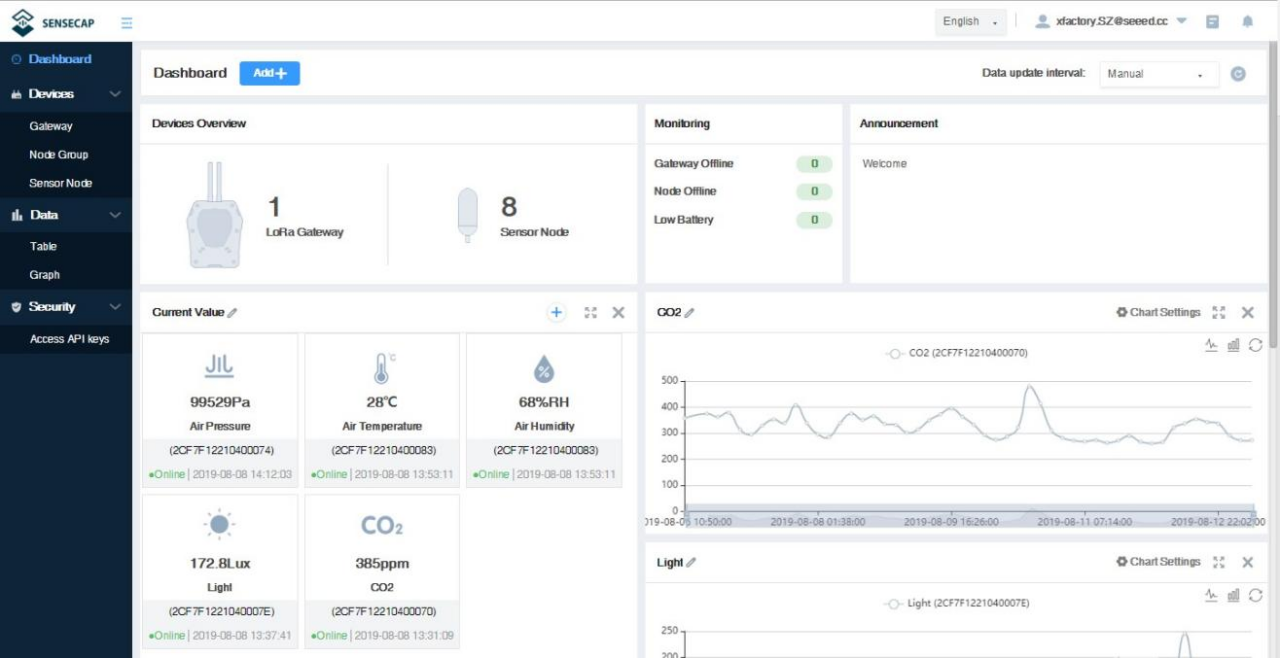
Dashboard: Including Device Overview, Announcement, Scene Data, and Data Chart, etc. Device Management: Manage SenseCAP devices.
Data Management: Manage data, including Data Table and Graph section, providing methods to search for data.
Subaccount System: Register subaccounts with different permissions.
Access Key Management: Manage Access Key (to access API service), including Key Create, Key Update, and Key Check.
Check the Quick Start for more details.
API Instruction
SenseCAP API is for users to manage IoT devices and data. It includes 3 types of API methods: HTTP protocol, MQTT protocol, and Websocket protocol.
With HTTP API, users can manage LoRa devices, to get raw data or historical data.
With MQTT API, users can subscribe to the sensor's real-time measurement data through the MQTT protocol.
With Websocket API, users can get real-time measurement data of sensors through Websocket protocol.
Please refer to this link for API User Guide

Connect to Helium Network
Please refer to the manual to connect sensors to the Helium public console:
Connect to The Things Network
- Please refer to this manual:
- Please refer to the link to use the TTN platform:
Device Installation
Step 1: Select an Appropriate Installation Location
Before installing the weather station, please consider the followings:
**(1)**Rain gauge must be cleaned every few months.
**(2)**Avoid radiant heat reflected from any adjacent buildings and structures. Ideally, the weather station should be installed at 1.5m (5') from any building, structure, ground, or rooftop.
**(3)**Choose an area of open space in direct sunlight without any obstruction of rain, wind, and sunlight.
**(4)**Transmission range between the weather station and the gateway could reach a distance of 2~10 km at the line of sight, providing there are no interfering obstacles in between or nearby such as trees, towers, or high voltage lines. Check the reception signal quality to ensure good reception.
**(5)**Household appliances such as fridges, lighting, and dimmers may pose Electro-magnetic interference (EMI), while Radio Frequency Interference (RFI) from devices operating in the same frequency range may cause signal intermittently. Choose a location at least 1-2 meters (3-5 feet) away from these interference sources to ensure the best reception.
Step 2: Installing the Weather Station
**(1)**Adjust the solar panel
The tilting angle of the solar panel can be adjusted vertically from 0° to 15°, 30°, 45°, and 60°positions depending on the area you are living in. For optimal power output year-round, please set the tilt angle that is closest to your latitude.
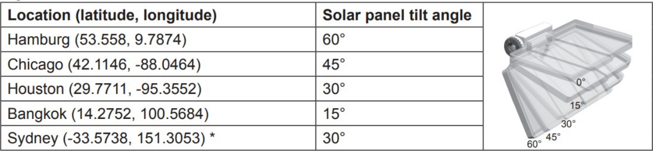
Sensors installed in Southern Hemisphere must have their solar panels facing North.
(2) Remove the solar panel protection film and loosen the screw lightly until the gears on the opposite side separated from lock position.
(3) Adjust the vertical angle of the solar panel (0°, 15°,30°, 45°, 60°) according to the latitude of your location and push the gear and tighten the screw until the gears are securely locked.

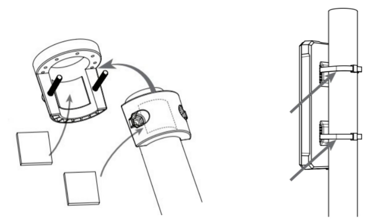
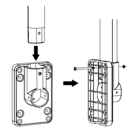
Step 3: Install the Mounting Pole
(1) Fasten the plastic pole onto your fix pole with mounting base, clamp, washers, screws and nuts. Following below sequences: Insert the plastic pole into the hole of the mounting stand, and then secure it with the screw and nut.
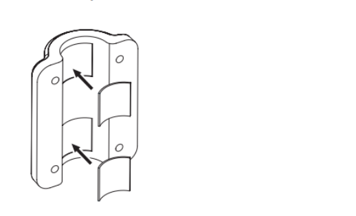
Apply 2 rubber pads on the mounting clamp.
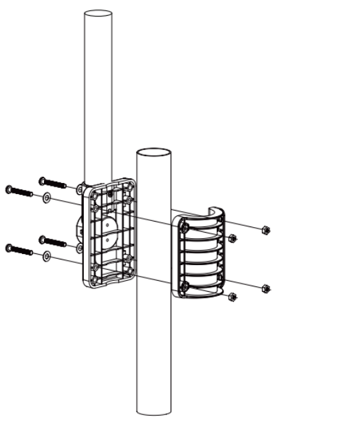
Fasten the mounting stand and clamp it together onto a fixed pole with 4 long screws and nuts.
(2) Apply 2 rubber pads on the inner sides of the mounting base and clamp the weather station, and loosely fasten them together.
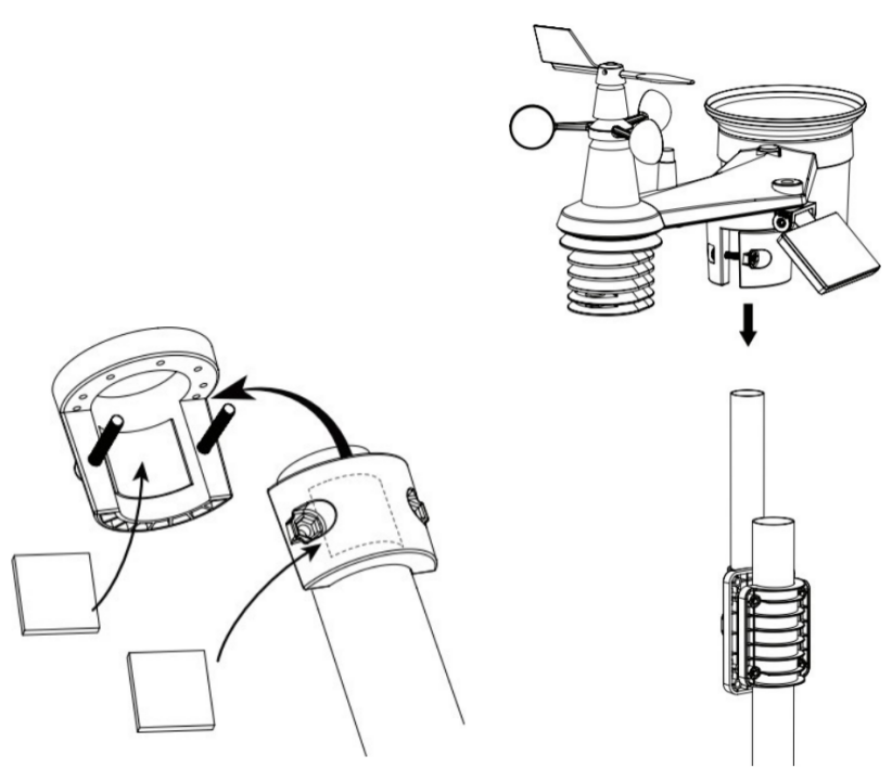
(3) Place the weather station over the mounting pole and align it to the North direction before fastening the screws.
Any metal object can attract lightning strikes, including the mounting pole. Never install a weather station on stormy days. If you want to install a weather station on a house or building,consult a licensed electrical engineer to ensure proper grounding.Direct lightning impact on a metal pole can damage or destroy your home.
Installing the sensor at a high location may result in personal injury or death.Perform as many initial inspections and operations as possible on the ground and in buildings or houses. Only install the weather station on clear, dry days.
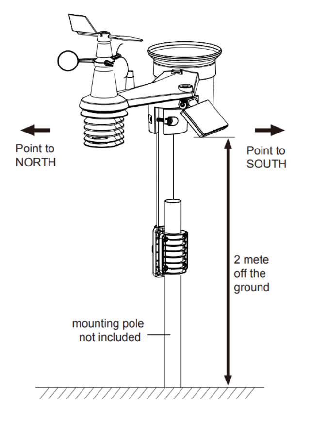
Step 4: Direction Alignment
Install the weather station in an open location with no obstructions above and around the sensor for accurate rain and wind measurement.
Locate the North (N) marker on top of the weather station and align the marker to point North upon final installation with a compass or GPS. Tighten the mounting bracket around a 30 to 40 mm diameter pole (not included) using two screws and nuts provided.
Use the bubble level on the weather station to make sure the sensor is completely level for proper measurement of rainfall, UV, and light intensity.
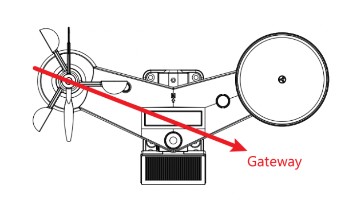
Recommendation for best wireless communication
Effective wireless communication is susceptible to noise interference in the environment, and distance and barriers between the sensor transmitter and the gateway.
- Installation direction. When installing equipment, in addition to the direction of wind direction, also needs to consider the direction of wireless transmission. In the direction shown, pointing to the gateway will get a better signal.
Distance. Path loss occurs naturally with distance. This device is rated to 10km by a line of sight (in an interference-free environment and without barriers). However, typically you will get 1~3km maximum in a real-life installation, which includes passing through barriers.
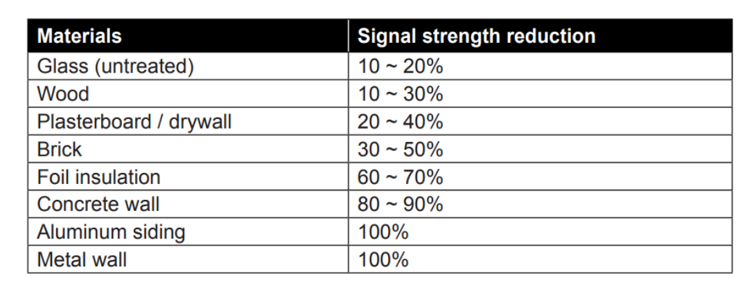
Barriers. Radio signals are blocked by metal barriers such as aluminum cladding. Please align the weather station and gateway to get them in a clear line of sight through the window if you have metal cladding.
The table below shows a typical level of reduction in signal strength each time the signal passed through these building materials (RF signal reduction for reference):
Trouble Shooting
Maintenance of Weather Station

Sensors can't join the LoRa network, how to do?
-
Check the gateway frequency configuration. Make sure the gateway and Sensors have the same uplink and downlink frequency.
-
Check the real-time log and click the config button of the sensor to see if there are any sensor data packets. If there are packets, check whether the gateway is sending downlink packets.
-
If the channels and other configurations are correct and the gateway logs do not have packets, please contact technical support.
Battery Life Prediction
The power consumption table is for reference only. The battery life depends on various factors, such as frequency band, distance from the gateway, and ambient temperature.