Seeed Studio 圆形显示屏扩展板的使用
本教程将详细说明如何使用 Round Display 上的扩展功能,包括 RTC 功能、SD 卡功能以及屏幕功能的使用。
入门指南
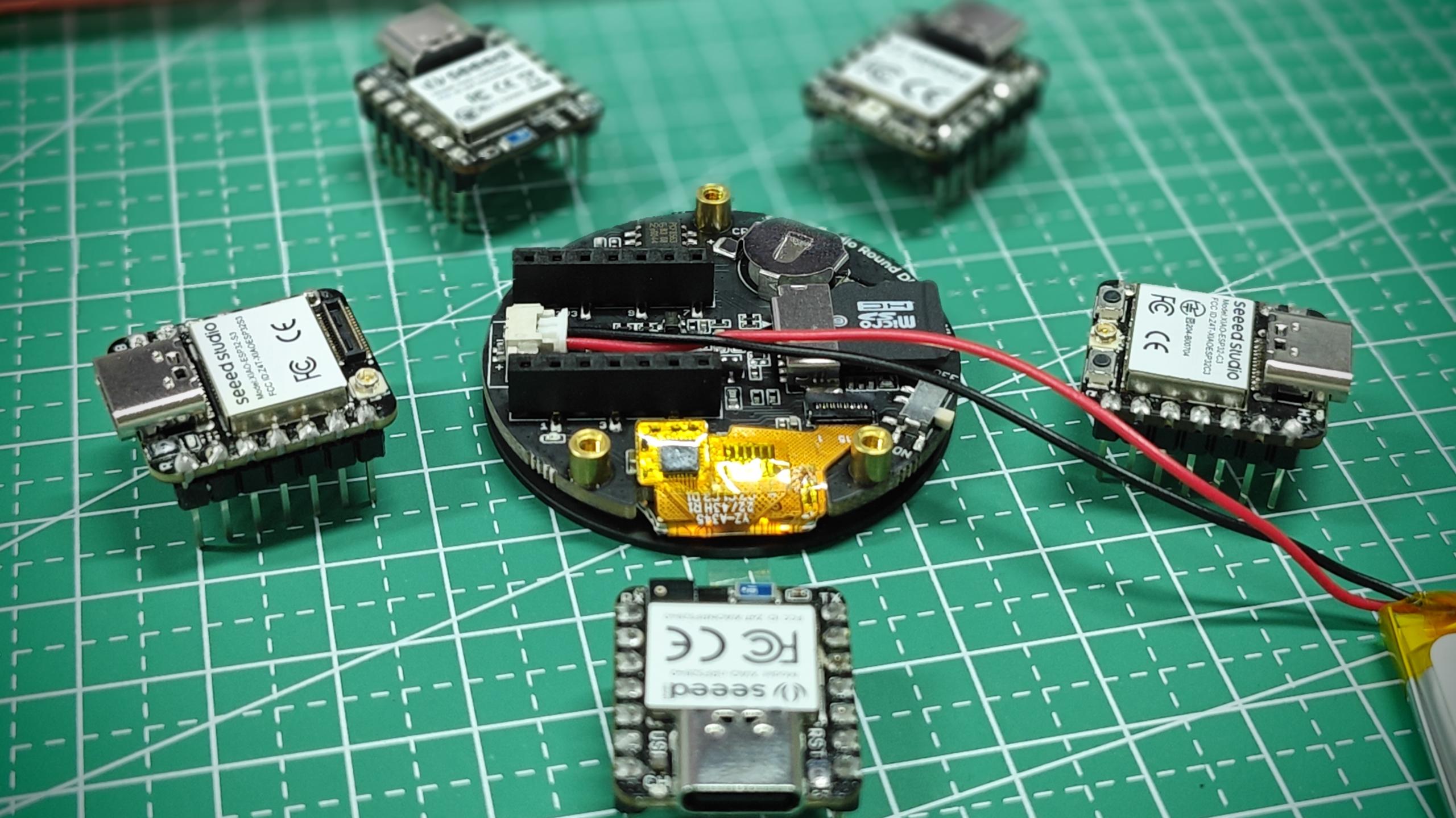
本教程的内容支持所有 XIAO 系列产品。因此你可以使用任意一款 XIAO 来完成本 Wiki 的内容。
如果你是第一次使用 Round Display,建议先阅读我们之前为其编写的准备内容,并根据其中的内容配置库的环境,以确保你可以顺利使用 Round Display。
安装 microSD 卡
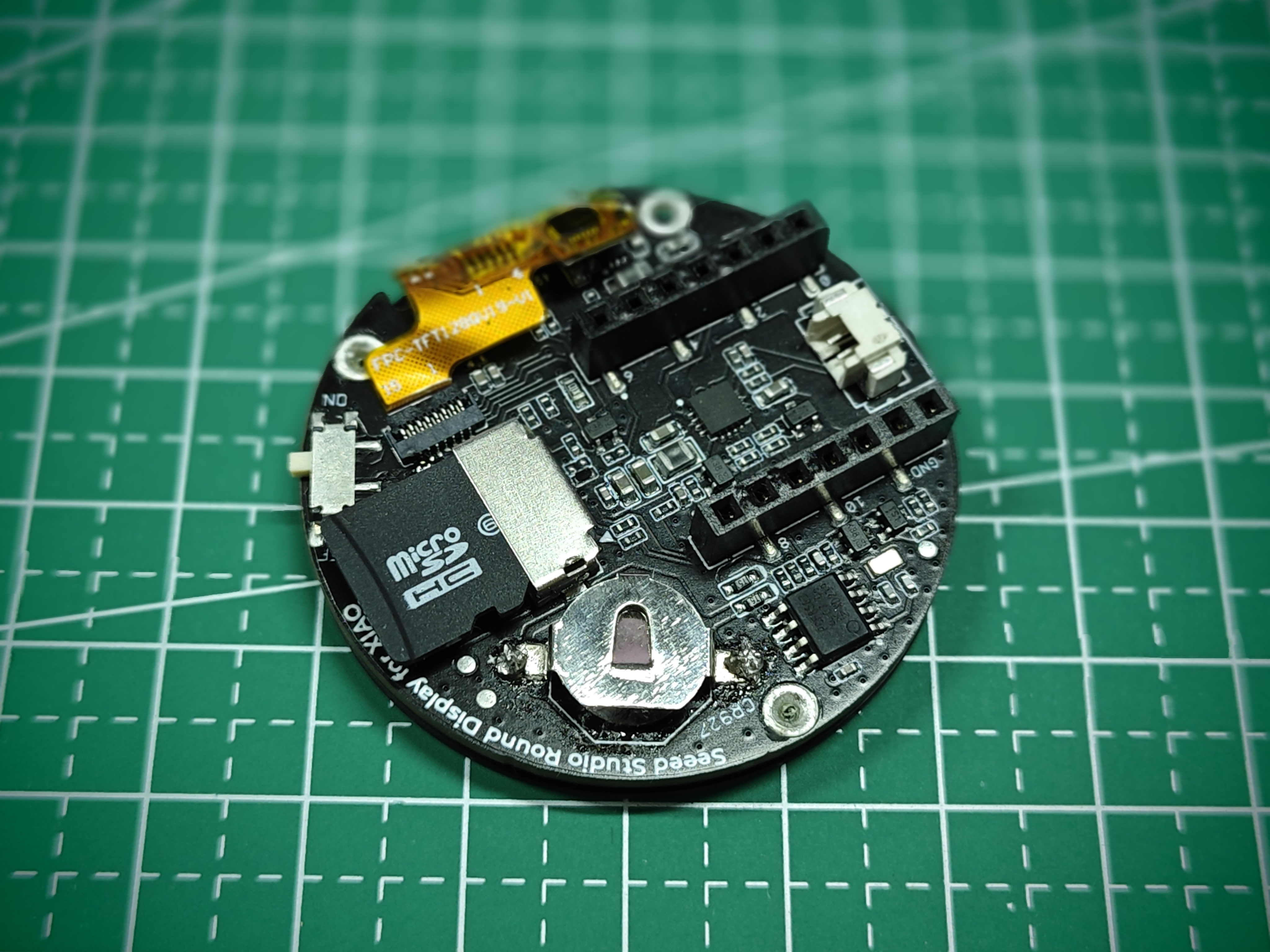
Round Display 支持使用格式为 FAT32、容量不大于 32GB 的 microSD 卡。安装 microSD 卡时,应将 microSD 卡的金手指朝向板子内部插入。
安装 RTC 电池
Round Display 支持 RTC 功能,并内置了 PCF8563T 芯片。如果你需要使用 RTC 功能,则可能需要一颗纽扣电池来维持 RTC 的工作。
我们建议使用 CR927 系列纽扣电池,安装时让正极(平面)朝外,负极(略微凸起的一面)朝内。
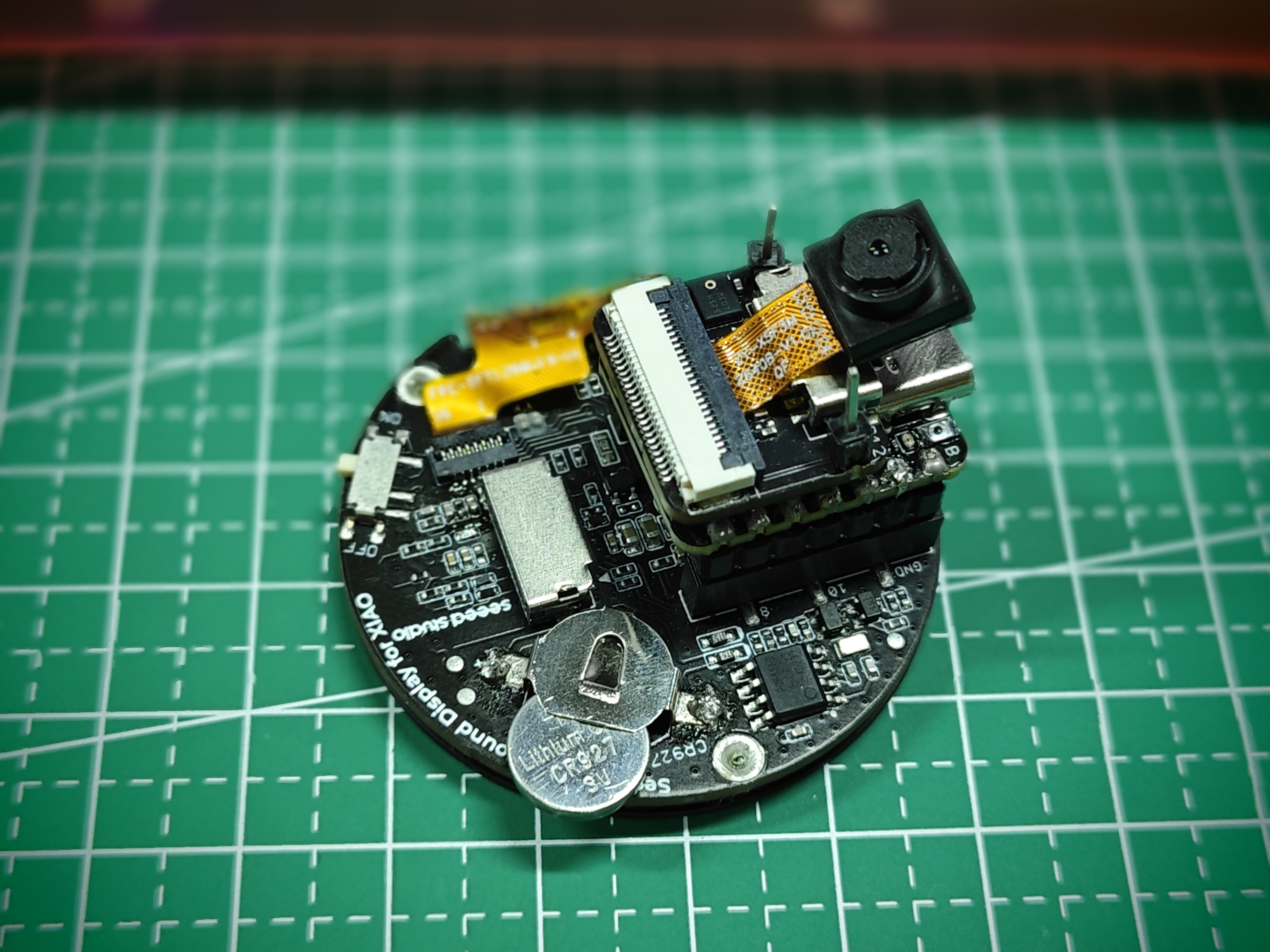
上图仅展示电池的安装方向,而非完全安装好的状态。正确安装电池时,应将电池完全插入电池座中。
安装供电电池
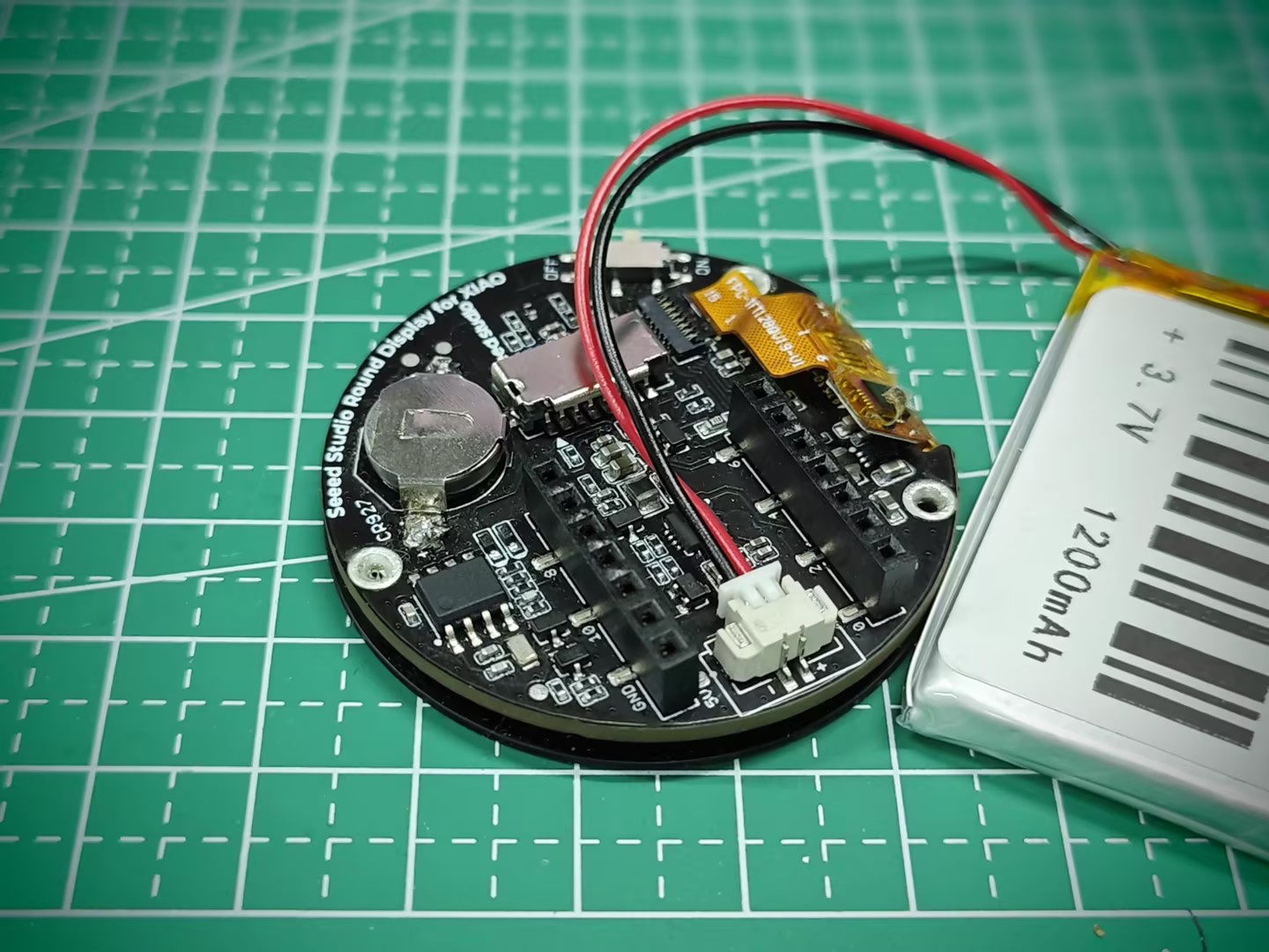
Round Display 支持外接 3.7V 锂电池。并且由于内置了电源管理芯片,可以通过 XIAO 的 USB 口为电池充电。
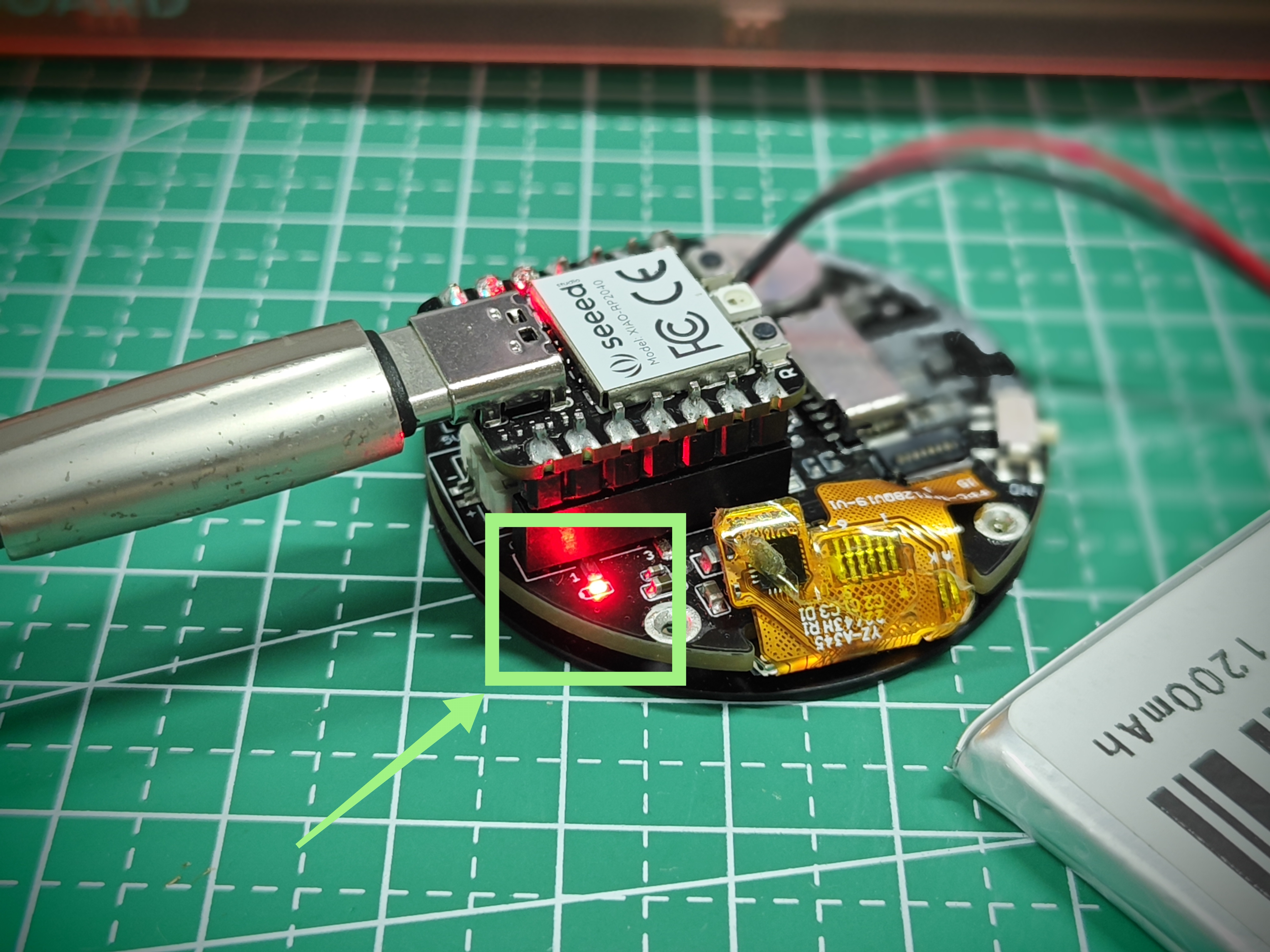
Round Display 还带有充电指示灯。它有三种状态:
- 未连接锂电池时,指示灯以低亮度常亮。
- 连接锂电池后,在为锂电池充电时,红灯以高亮度常亮。
- 连接锂电池后,当电池充满电时,指示灯熄灭。
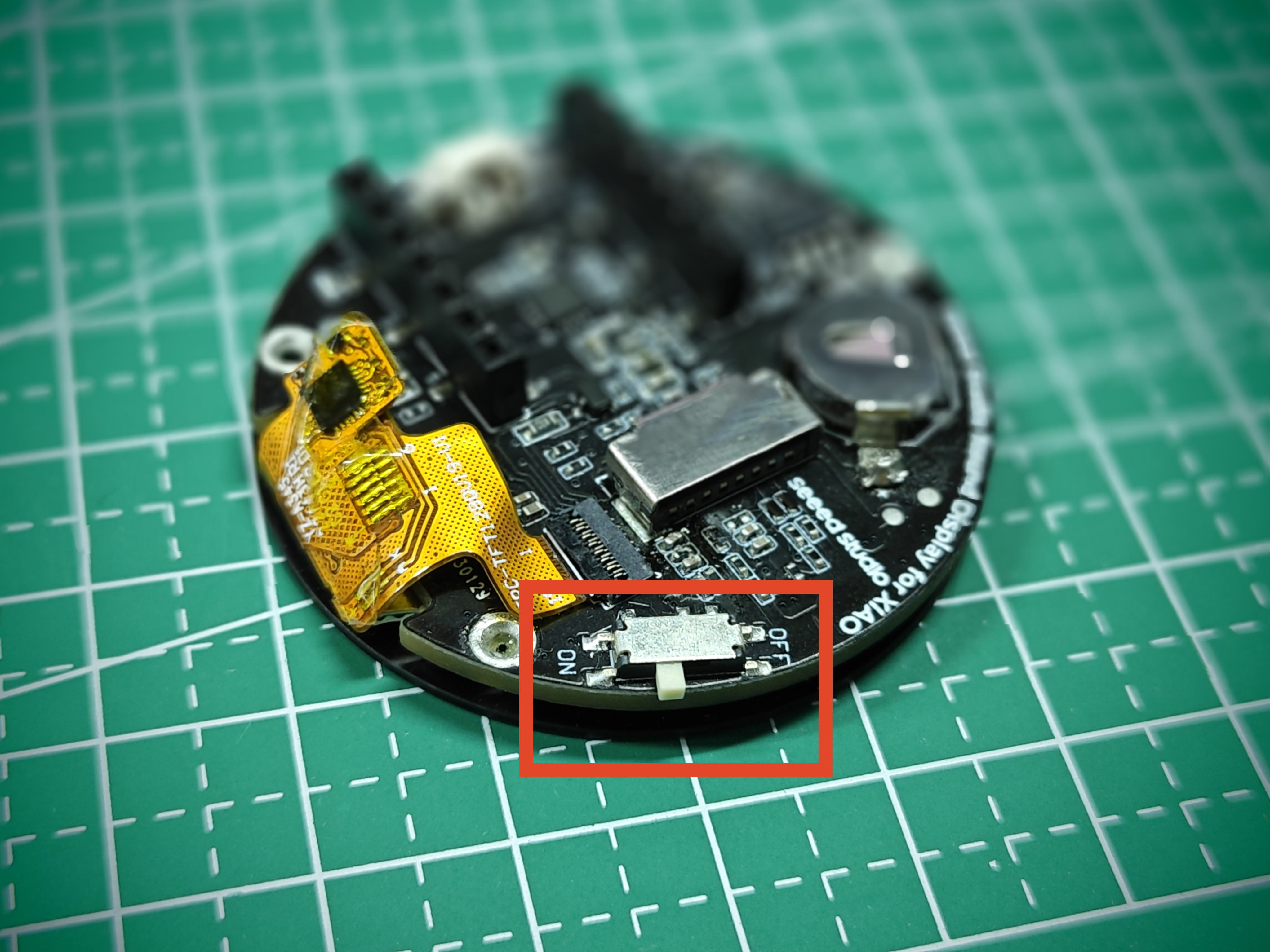
Round Display 开关
Round Display 上还带有一个开关。该开关用于控制显示屏以及对 XIAO 的供电。当你将开关拨到 OFF 时,电池将不会为 XIAO 供电,显示屏也会关闭。当你将开关拨到 ON 时,显示屏会点亮,并且电池会为 XIAO 供电(前提是已安装供电电池),以确保程序运行。
此处所说的为 XIAO 供电,是指通过 Round Display 为 XIAO 供电。如果你是直接为 XIAO 供电,那么 Round Display 上的开关无法切断对 XIAO 的供电。如果你希望通过 Round Display 上的开关来控制整个设备,则需要在 Round Display 上安装供电电池。
另外需要注意的是,一些 XIAO(例如 XIAO ESP32C3)在断电后再次上电运行程序时,可能需要按下 XIAO 上的 Reset 按钮才能开始工作。
Round Display 电路设计
在本节中,我们将截取 Round Display 硬件的电路原理图,并告知用户 Round Display 硬件中使用了 XIAO 上的哪些 IO 引脚,以避免 IO 使用上的冲突。
测量电池电压引脚
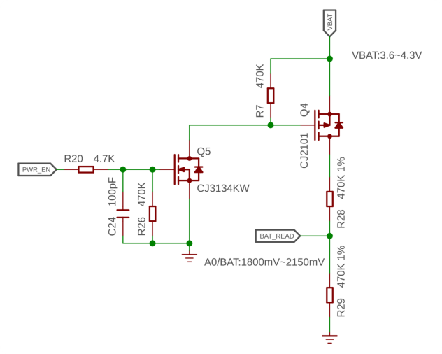
在 Round Display 的设计中,我们使用了 XIAO 上的 A0/D0 引脚连接到板载电池的电路。通过读取该引脚的模拟值即可获得剩余电量。
SD 卡电路引脚
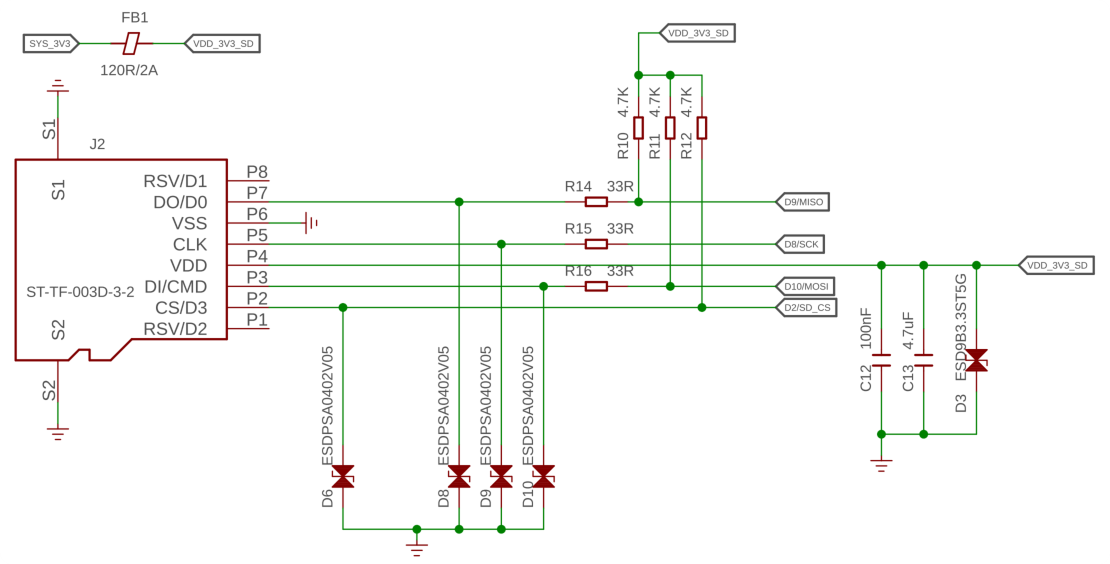
SD 卡部分使用了 XIAO 上的四个 IO 口,其用途如下表所示。
| XIAO GPIO | microSD 卡座 |
|---|---|
| D2 | CS |
| D8 | SCK |
| D9 | MISO |
| D10 | MOSI |
RTC 电路引脚
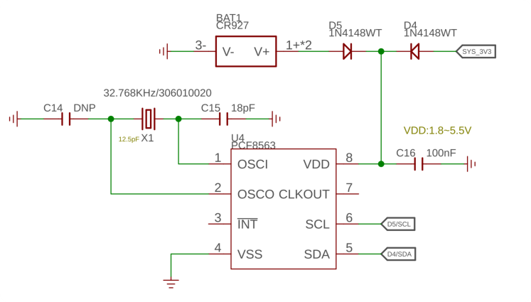
RTC 功能使用 IIC 协议,因此占用了 D5 (SCL) 和 D4 (SDA) 引脚。
触摸屏电路引脚
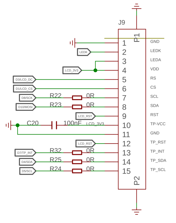
触摸屏部分使用了 XIAO 上的四个 IO 口,其用途如下表所示。
| XIAO GPIO | 触摸屏 |
|---|---|
| D4 (SDA) | 触摸屏 IIC |
| D5 (SCL) | 触摸屏 IIC |
| D3 | LCD_DC |
| D1 | LCD_CS |
| D7 | TP_INT |
| D6 | 屏幕背光 |
Round Display 库概览
Round Display 的绝大部分软件开发是基于 XIAO 自身的硬件支持完成的。图形部分基于 TFT 库、LVGL 库以及 Arduino GFX 库。
为了方便用户使用 Round Display 上的各项功能,我们编写了一个单独的库,主要是调用上述库的接口,以降低用户在后续进行自主开发时的门槛。在本章中,我们将重点介绍我为 Round Display 准备的这些库都有哪些功能,以及分别如何使用它们。
lv_xiao_round_screen.h
lv_xiao_round_screen.h 文件是 Round Display 库中的一个头文件,用于驱动屏幕的显示和触摸功能。
在该文件的开头进行了宏定义检查,目的是要求使用 Round Display 的开发者在绘制屏幕图案时,需要选择你想要开发所使用的图形库。有两个选择,TFT 和 Arduino GFX。如果你选择 TFT 库,那么它就是可以支持 LVGL 的那个。
#if defined(USE_TFT_ESPI_LIBRARY) && defined(USE_ARDUINO_GFX_LIBRARY)
#error "More than one graphics library is defined."
#elif defined(USE_TFT_ESPI_LIBRARY)
#include <TFT_eSPI.h>
TFT_eSPI tft = TFT_eSPI(SCREEN_WIDTH, SCREEN_HEIGHT);
#elif defined(USE_ARDUINO_GFX_LIBRARY)
#include <Arduino_GFX_Library.h>
这样设计的原因是,不同的 XIAO 在不同图形库上绘制图案时各有优势。例如,如果你使用的是 XIAO nRF52840,那么使用 Arduino GFX 库会在内存占用和稳定性方面更有优势。对于 XIAO ESP32S3 这样的大内存 XIAO,在处理 LVGL 等图形库时具有天然优势,也能够绘制更复杂的图案和 UI。
所以如果你需要使用 Round Display 绘制图案,不要忘记先选择你想使用的图形库,并在 Arduino 程序的开头进行定义。
- 如果你想使用 TFT 库或 LVGL 库:
#define USE_TFT_ESPI_LIBRARY
- 如果你想使用 Arduino GFX 库:
#define USE_ARDUINO_GFX_LIBRARY
-
void xiao_disp_init(void): 该函数用于初始化显示背光,并将显示屏旋转到初始位置,设备显示底板颜色为纯黑色。该函数一般不会单独使用,当需要初始化时,会改用lv_xiao_disp_init()函数。 -
void lv_xiao_disp_init(void): 初始化背光,并初始化显示驱动。通常用于显示初始化。 -
bool chsc6x_is_pressed(void): 该函数用于检测屏幕是否被触摸,如果屏幕被触摸则返回Ture。 -
void lv_xiao_touch_init(void): 该函数用于初始化触摸屏及其驱动。 -
void chsc6x_read( lv_indev_drv_t * indev_driver, lv_indev_data_t * data ): 该函数用于获取触摸屏的坐标点。
lv_hardware_test.h
lv_hardware_test.h 文件是 Round Display 库中示例 HardwareTest 的头文件。该头文件为 Round Display 准备了大部分硬件使用函数。
如果你想使用这个头文件中的函数,可以将该文件直接复制到你的 Arduino 文件所在的同一文件目录下。
-
int32_t battery_level_percent(void): 通过调用该函数,你可以读取并计算电池电量百分比,以便在应用中显示电池电量。 -
void lv_hardware_test(void): 该函数用于测试所有硬件功能,包括屏幕显示、屏幕触摸、RTC 时钟以及电池电量。你可以参考该函数的写法来完成你想要的 Round Display 功能开发。
KE 按键与 GPIO
在新版 Round Display 上,我们设计了一个 KE 开关,用于选择性地释放某些 GPIO 供用户选择使用。
KE 开关被设计在 microSD 卡槽与连接 XIAO 的那排引脚中间的位置。
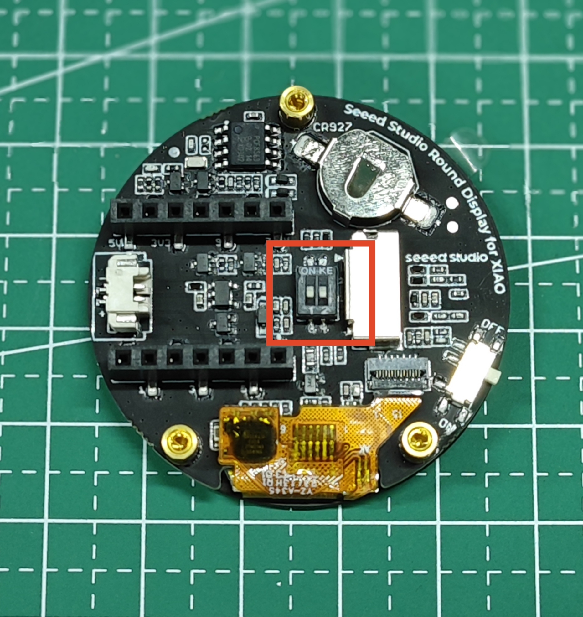
该开关的电路设计如下图所示。
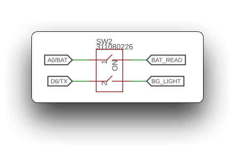
这意味着当开关闭合 (拨到 ON 一侧) 时,Round Display 的电池电压读取功能和显示背光功能将可用。
当开关断开 (拨到 digital 一侧) 时,XIAO 上的 A0 和 D6 引脚则处于可用状态。
测量电池电压
由于 XIAO 的 IO 引脚数量有限,大多数 XIAO 虽然在部分型号上配置了电源管理芯片以支持外接电池,但仍无法测量电池电压。
但如果你选择使用 Round Dislay 并通过屏幕为 XIAO 供电,那么测量电池电压就可以实现了。
下面是一个测量电池电压的示例程序。函数 battery_level_percent() 选自 lv_hardware_test.h 文件。
#define NUM_ADC_SAMPLE 20           // Sampling frequency
#define RP2040_VREF 3300            // When you use the XIAO RP2040, you need to measure the actual voltage at the 3.3V pin and modify that value. (unit: mV)
#define BATTERY_DEFICIT_VOL 1850    // Battery voltage value at loss of charge
#define BATTERY_FULL_VOL 2450       // Battery voltage value at full charge

int32_t battery_level_percent(void)
{
  int32_t mvolts = 0;
#if defined(CONFIG_IDF_TARGET_ESP32S3) || defined(CONFIG_IDF_TARGET_ESP32C3)
  for(int8_t i=0; i<NUM_ADC_SAMPLE; i++){
    mvolts += analogReadMilliVolts(D0);
  }
  mvolts /= NUM_ADC_SAMPLE;
#elif defined(ARDUINO_SEEED_XIAO_NRF52840_SENSE) || defined(ARDUINO_SEEED_XIAO_NRF52840)
  analogReference(AR_INTERNAL2V4);  // 0.6V ref  1/4 Gain
  int32_t adc_raw = 0;
  for(int8_t i=0; i<NUM_ADC_SAMPLE; i++){
    adc_raw += analogRead(D0);
  }
  adc_raw /= NUM_ADC_SAMPLE;
  mvolts = 2400 * adc_raw / (1<<12);
#elif defined(ARDUINO_SEEED_XIAO_RP2040)
  int32_t adc_raw = 0;
  for(int8_t i=0; i<NUM_ADC_SAMPLE; i++){
    adc_raw += analogRead(D0);
  }
  adc_raw /= NUM_ADC_SAMPLE;
  mvolts = RP2040_VREF * adc_raw / (1<<12);
#endif
  int32_t level = (mvolts - BATTERY_DEFICIT_VOL) * 100 / (BATTERY_FULL_VOL-BATTERY_DEFICIT_VOL); // 1850 ~ 2100
  level = (level<0) ? 0 : ((level>100) ? 100 : level);
  return level;
}

void setup() {
  // put your setup code here, to run once:
  Serial.begin(115200);
  while(!Serial);

  analogReadResolution(12);
}

void loop() {
  // put your main code here, to run repeatedly:
  int32_t batteryVal = battery_level_percent();
  Serial.print("The percentage of power remaining is: ");
  Serial.print(batteryVal);
  Serial.print(" %");
  Serial.println();
  delay(1000);
}
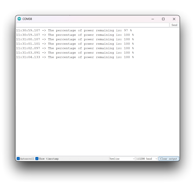
该程序并不是通用程序,测得的电池百分比可能不够准确。这是因为每个人使用的电池、芯片和开发板都不同,所以在执行该程序时,你可能需要根据实际情况对程序进行修改。修改方法请参考本节的 program annotation 小节。
选择你正在使用的 XIAO 开发板,上传程序,打开串口监视器,并将波特率设置为 115200。如果你已经连接电池并上电,你应该可以在串口监视器中看到电池电压。
Program annotation
这段代码使用 ADC 测量电池电压并计算电池电量百分比。具体实现会根据硬件平台的不同而有所差异:
- 对于 ESP32-S3 和 ESP32-C3 平台,使用
analogReadMilliVolts函数读取模拟电压值,然后对多次采样取平均值,得到电池电压的平均值。 - 对于 Seeeduino XIAO NRF52840 平台,首先使用
analogReference函数将参考电压指定为 2.4V,然后使用 analogRead 函数读取模拟电压值,并计算电池电压的平均值。 - 对于 Seeeduino XIAO RP2040 平台,使用
analogRead函数读取模拟电压值,并计算电池电压的平均值。
无论哪种情况,都会先计算电池电压的平均值,然后使用公式 (mvolts - BATTERY_DEFICIT_VOL) * 100 / (BATTERY_FULL_VOL - BATTERY_DEFICIT_VOL) 计算电池电量百分比,其中 mvolts 为电池电压平均值,BATTERY_DEFICIT_VOL 为电池的最低工作电压,BATTERY_FULL_VOL 为电池的最高电压。最后,代码会对电池电量百分比进行限制,确保其在 0 到 100 之间。
总的来说,在使用本程序时,以下参数决定了电压测量的准确性。
#define RP2040_VREF 3300            // When you use the XIAO RP2040, you need to measure the actual voltage at the 3.3V pin and modify that value. (unit: mV)
#define BATTERY_DEFICIT_VOL 1850    // Battery voltage value at loss of charge
#define BATTERY_FULL_VOL 2450       // Battery voltage value at full charge
你首先需要做的是,在你购买的电池处于亏电/满电状态时,分别获取其模拟值。
你可以通过使用这个函数来获取电池的模拟值。你需要在电池满电和亏电两种状态下各获取一次该值。
int32_t battery_test(void)
{
  int32_t mvolts = 0;
#if defined(CONFIG_IDF_TARGET_ESP32S3) || defined(CONFIG_IDF_TARGET_ESP32C3)
  for(int8_t i=0; i<NUM_ADC_SAMPLE; i++){
    mvolts += analogReadMilliVolts(D0);
  }
  mvolts /= NUM_ADC_SAMPLE;
#elif defined(ARDUINO_SEEED_XIAO_NRF52840_SENSE) || defined(ARDUINO_SEEED_XIAO_NRF52840)
  analogReference(AR_INTERNAL2V4);  // 0.6V ref  1/4 Gain
  int32_t adc_raw = 0;
  for(int8_t i=0; i<NUM_ADC_SAMPLE; i++){
    adc_raw += analogRead(D0);
  }
  adc_raw /= NUM_ADC_SAMPLE;
  mvolts = 2400 * adc_raw / (1<<12);
#elif defined(ARDUINO_SEEED_XIAO_RP2040)
  int32_t adc_raw = 0;
  for(int8_t i=0; i<NUM_ADC_SAMPLE; i++){
    adc_raw += analogRead(D0);
  }
  adc_raw /= NUM_ADC_SAMPLE;
  mvolts = RP2040_VREF * adc_raw / (1<<12);
#endif
  return mvolts;
}
battery_test() 函数实际上就是将 battery_level_percent() 函数中最后两行用于计算百分比的代码去掉后的版本。
然后只需要根据你测得的数值,修改程序中对应的参数值即可。
如果你使用的是 XIAO RP2040,那么你还需要额外做一步:使用电压表测量 XIAO RP2040 上 3.3V 引脚的实际电压。将测得的电压值转换为 mV 单位,并修改对应的程序。
例如,下面是我使用自己的 XIAO RP2040 和电池进行实际测量得到的结果。
#define RP2040_VREF 3080
#define BATTERY_DEFICIT_VOL 1541
#define BATTERY_FULL_VOL 1791
RTC 功能
在 RTC 功能部分,我们主要分为以下四个小节来介绍它的应用。
- 首先,对于不具备网络功能的 XIAO,可以通过手动设置初始时间来校准 RTC。
- 然后在纽扣电池的帮助下为 RTC 供电,以便持续获得准确时间。
- 对于具备网络功能的 XIAO,可以使用网络功能来校准时间。
- 结合 RTC 功能绘制一个简单的钟表表盘。
RTC 的离线手动校准
下面是一个用于手动校准 RTC 时间的示例程序。设置被放置在 Setup() 函数中,以确保设置程序只执行一次。该过程是为不具备网络功能的 XIAO 设置初始 RTC 时间的最高效方式。
#include "I2C_BM8563.h"

I2C_BM8563 rtc(I2C_BM8563_DEFAULT_ADDRESS, Wire);

void setup() {
  // Init Serial
  Serial.begin(115200);
  while(!Serial);
  delay(50);

  // Init I2C
  Wire.begin();

  // Init RTC
  rtc.begin();

  // Set RTC Date
  I2C_BM8563_DateTypeDef dateStruct;
  dateStruct.weekDay = 3;
  dateStruct.month = 4;
  dateStruct.date = 26;
  dateStruct.year = 2023;
  rtc.setDate(&dateStruct);

  // Set RTC Time
  I2C_BM8563_TimeTypeDef timeStruct;
  timeStruct.hours   = 9;
  timeStruct.minutes = 43;
  timeStruct.seconds = 10;
  rtc.setTime(&timeStruct);

  Serial.println("RTC time calibration complete!");
}

void loop() {

}
上传程序并打开串口监视器后,RTC 时间将开始校准。当出现 RTC time calibration complete! 时,表示校准完成。
获取 RTC 时间
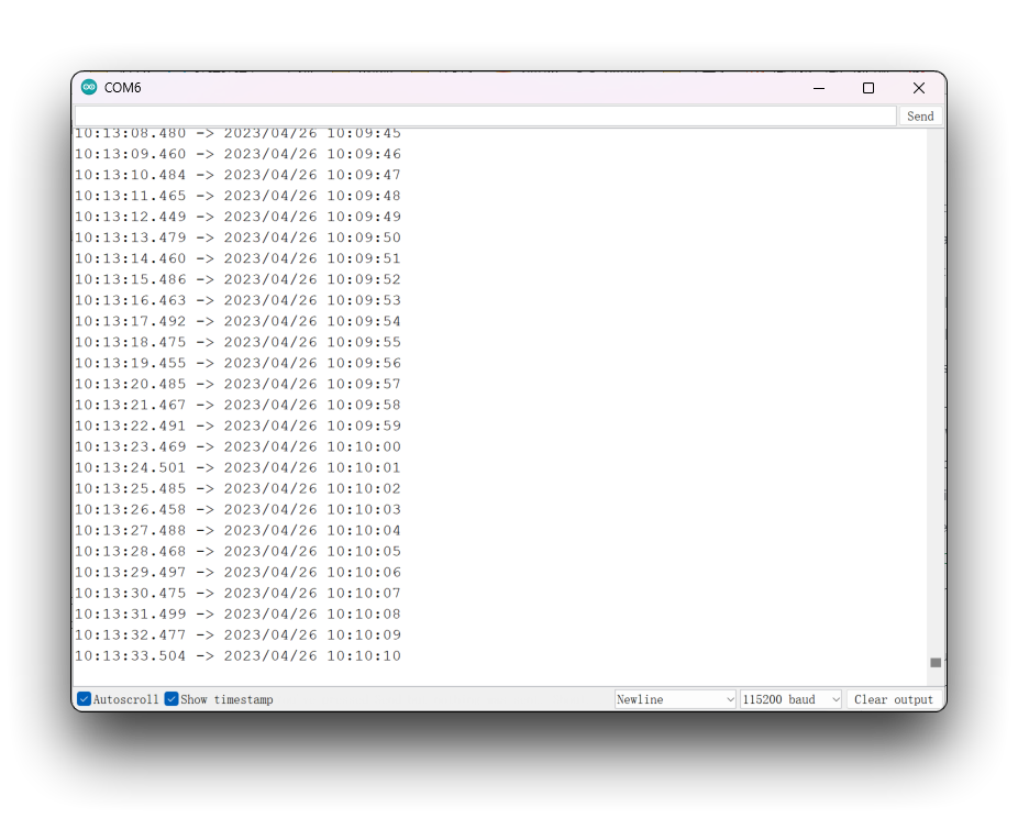
下面的程序每秒获取一次 RTC 的时间,并在串口监视器中打印出来。
获取 RTC 时间的程序可以在完成上述手动校准程序后使用。时间校准程序只需要执行一次,在纽扣电池供电下,RTC 时钟就可以持续工作,之后你只需要使用获取时间的程序来获得准确时间。
我们不建议将校准时间和获取时间的程序放在一起使用,否则当 XIAO 上电时,两者都会根据你配置的时间重新设置一次,这样你将永远无法获得准确时间。
#include "I2C_BM8563.h"

I2C_BM8563 rtc(I2C_BM8563_DEFAULT_ADDRESS, Wire);

void setup() {
  // Init Serial
  Serial.begin(115200);
  delay(50);

  // Init I2C
  Wire.begin();

  // Init RTC
  rtc.begin();
}

void loop() {
  I2C_BM8563_DateTypeDef dateStruct;
  I2C_BM8563_TimeTypeDef timeStruct;

  // Get RTC
  rtc.getDate(&dateStruct);
  rtc.getTime(&timeStruct);

  // Print RTC
#if defined(CONFIG_IDF_TARGET_ESP32S3) || defined(CONFIG_IDF_TARGET_ESP32C3)
  Serial.printf("%04d/%02d/%02d %02d:%02d:%02d\n",
              dateStruct.year,
              dateStruct.month,
              dateStruct.date,
              timeStruct.hours,
              timeStruct.minutes,
              timeStruct.seconds
              );
#else
  Serial.print(dateStruct.year);
  Serial.print(", ");
  Serial.print(dateStruct.month);
  Serial.print(", ");
  Serial.print(dateStruct.date);
  Serial.print(", ");
  Serial.print(timeStruct.hours);
  Serial.print(", ");
  Serial.print(timeStruct.minutes);
  Serial.print(", ");
  Serial.print(timeStruct.seconds);
  Serial.println();
#endif

  // Wait
  delay(1000);
}
基于网络校准 RTC 时间
对于具备网络功能的 XIAO,事情似乎变得容易得多。有了网络,你甚至不需要使用纽扣电池来让 RTC 即开即用地工作,只需要在每次上电时通过网络进行校时即可。
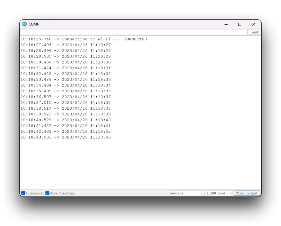
下面是一个用于网络校时并在串口监视器上输出 RTC 时间读数的示例程序。
该程序仅适用于 XIAO ESP32 系列。因为只有该系列具备网络功能。
#include "I2C_BM8563.h"
#include <WiFi.h>

I2C_BM8563 rtc(I2C_BM8563_DEFAULT_ADDRESS, Wire);

const char* ntpServer = "time.cloudflare.com";
const char *ssid     = "YOUR_SSID";
const char *password = "YOUR_PASSWORD";

void setup() {
  // Init Serial
  Serial.begin(115200);
  delay(50);

  // Connect to an access point
  WiFi.begin(ssid, password);
  Serial.print("Connecting to Wi-Fi ");
  while (WiFi.status() != WL_CONNECTED) {
    delay(500);
    Serial.print(".");
  }
  Serial.println(" CONNECTED");

  // Set ntp time to local
  configTime(9 * 3600, 0, ntpServer);

  // Init I2C
  Wire.begin();

  // Init RTC
  rtc.begin();

  // Get local time
  struct tm timeInfo;
  if (getLocalTime(&timeInfo)) {
    // Set RTC time
    I2C_BM8563_TimeTypeDef timeStruct;
    timeStruct.hours   = timeInfo.tm_hour;
    timeStruct.minutes = timeInfo.tm_min;
    timeStruct.seconds = timeInfo.tm_sec;
    rtc.setTime(&timeStruct);

    // Set RTC Date
    I2C_BM8563_DateTypeDef dateStruct;
    dateStruct.weekDay = timeInfo.tm_wday;
    dateStruct.month   = timeInfo.tm_mon + 1;
    dateStruct.date    = timeInfo.tm_mday;
    dateStruct.year    = timeInfo.tm_year + 1900;
    rtc.setDate(&dateStruct);
  }
}

void loop() {
  I2C_BM8563_DateTypeDef dateStruct;
  I2C_BM8563_TimeTypeDef timeStruct;

  // Get RTC
  rtc.getDate(&dateStruct);
  rtc.getTime(&timeStruct);

  // Print RTC
#if defined(CONFIG_IDF_TARGET_ESP32S3) || defined(CONFIG_IDF_TARGET_ESP32C3)
    Serial.printf("%04d/%02d/%02d %02d:%02d:%02d\n",
                dateStruct.year,
                dateStruct.month,
                dateStruct.date,
                timeStruct.hours,
                timeStruct.minutes,
                timeStruct.seconds
               );
#else
     Serial.print(dateStruct.year);
     Serial.print(", ");
     Serial.print(dateStruct.month);
     Serial.print(", ");
     Serial.print(dateStruct.date);
     Serial.print(", ");
     Serial.print(timeStruct.hours);
     Serial.print(", ");
     Serial.print(timeStruct.minutes);
     Serial.print(", ");
     Serial.print(timeStruct.seconds);
     Serial.println();
#endif

  // Wait
  delay(1000);
}
在使用该程序时,请根据你的实际情况填写网络的名称和密码。上传程序后,打开串口监视器并将波特率设置为 115200,即可看到准确时间。
基于 RTC 时间的简单表盘
下面的程序是一个基于 RTC 时钟绘制的表盘程序。
下面的程序仅兼容除 XIAO nRF52840 之外的 XIAO。XIAO nRF52840 目前在与 TFT 的兼容性方面存在问题。但你可以考虑使用 Arduino GFX 库或 LVGL 来绘制表盘。
#include <Arduino.h>
#include <TFT_eSPI.h>
#include <SPI.h>
#include "I2C_BM8563.h"
#include <Wire.h>

#define USE_TFT_ESPI_LIBRARY

#include "lv_xiao_round_screen.h"

I2C_BM8563 rtc(I2C_BM8563_DEFAULT_ADDRESS, Wire);

#if defined(CONFIG_IDF_TARGET_ESP32S3) || defined(CONFIG_IDF_TARGET_ESP32C3)
#include "esp_wifi.h"
#include "WiFi.h"

  const char *ntpServer = "time.cloudflare.com";
  const char *ssid     = "YOUR_SSID";
  const char *password = "YOUR_PASSWORD";
#elif defined(ARDUINO_SEEED_XIAO_NRF52840_SENSE) || defined(ARDUINO_SEEED_XIAO_NRF52840)
#error "This procedure is not applicable to XIAO nRF52840 series, please replace other XIAO and try again."
#endif


//TFT_eSPI tft = TFT_eSPI();  // Invoke library, pins defined in User_Setup.h
TFT_eSprite face = TFT_eSprite(&tft);

#define CLOCK_X_POS 0
#define CLOCK_Y_POS 0

#define CLOCK_FG   TFT_SKYBLUE
#define CLOCK_BG   TFT_NAVY
#define SECCOND_FG TFT_RED
#define LABEL_FG   TFT_GOLD

#define CLOCK_R       240.0f / 2.0f // Clock face radius (float type)
#define H_HAND_LENGTH CLOCK_R/2.0f
#define M_HAND_LENGTH CLOCK_R/1.4f
#define S_HAND_LENGTH CLOCK_R/1.3f

// Calculate 1 second increment angles. Hours and minute hand angles
// change every second so we see smooth sub-pixel movement
#define SECOND_ANGLE 360.0 / 60.0
#define MINUTE_ANGLE SECOND_ANGLE / 60.0
#define HOUR_ANGLE   MINUTE_ANGLE / 12.0

// Sprite width and height
#define FACE_W CLOCK_R * 2 + 1
#define FACE_H CLOCK_R * 2 + 1

// Time h:m:s
uint8_t h = 0, m = 0, s = 0;

float time_secs = h * 3600 + m * 60 + s;

// Time for next tick
uint32_t targetTime = 0;

// =========================================================================
// Setup
// =========================================================================
void setup() {
  Serial.begin(115200);
  Serial.println("Booting...");

  // Initialise the screen
  tft.init();

  // Ideally set orientation for good viewing angle range because
  // the anti-aliasing effectiveness varies with screen viewing angle
  // Usually this is when screen ribbon connector is at the bottom
  tft.setRotation(0);
  tft.fillScreen(TFT_BLACK);

  // Create the clock face sprite
  //face.setColorDepth(8); // 8 bit will work, but reduces effectiveness of anti-aliasing
  face.createSprite(FACE_W, FACE_H);

  // Draw the whole clock - NTP time not available yet
  renderFace(time_secs);

#if defined(CONFIG_IDF_TARGET_ESP32S3) || defined(CONFIG_IDF_TARGET_ESP32C3)
  WiFi.begin(ssid, password);
  while ( WiFi.status() != WL_CONNECTED )
  {
    delay ( 500 );
    Serial.print ( "." );
  }
  configTime(8 * 3600, 0, ntpServer);
#endif

  Wire.begin();
  rtc.begin();

//  struct tm timeInfo;
  I2C_BM8563_TimeTypeDef timeStruct;
  I2C_BM8563_DateTypeDef dateStruct;

// In case of XIAO ESP32 series, use network timing.
#if defined(CONFIG_IDF_TARGET_ESP32S3) || defined(CONFIG_IDF_TARGET_ESP32C3)
  struct tm timeInfo;
  if (getLocalTime(&timeInfo)) {
    timeStruct.hours   = timeInfo.tm_hour;
    timeStruct.minutes = timeInfo.tm_min;
    timeStruct.seconds = timeInfo.tm_sec;
    rtc.setTime(&timeStruct);
  }
#else
  // Set RTC time, Other XIAOs do not have network functions and require manual time alignment.
  // Please note that the setting time should be set only once.
  timeStruct.hours   = 9;
  timeStruct.minutes = 43;
  timeStruct.seconds = 10;
  rtc.setTime(&timeStruct);
#endif

  targetTime = millis() + 100;
  rtc.getTime(&timeStruct);
  time_secs = timeStruct.hours * 3600 + timeStruct.minutes * 60 + timeStruct.seconds;
}

// =========================================================================
// Loop
// =========================================================================
void loop() {
  // Update time periodically
  if (targetTime < millis()) {

    // Update next tick time in 100 milliseconds for smooth movement
    targetTime = millis() + 100;

    // Increment time by 100 milliseconds
    time_secs += 0.100;

    // Midnight roll-over
    if (time_secs >= (60 * 60 * 24)) time_secs = 0;

    // All graphics are drawn in sprite to stop flicker
    renderFace(time_secs);

    I2C_BM8563_DateTypeDef dateStruct;
    I2C_BM8563_TimeTypeDef timeStruct;

    // Get RTC
    rtc.getTime(&timeStruct);

    // Print RTC
#if defined(CONFIG_IDF_TARGET_ESP32S3) || defined(CONFIG_IDF_TARGET_ESP32C3)
    Serial.printf("%02d:%02d:%02d\n",
                timeStruct.hours,
                timeStruct.minutes,
                timeStruct.seconds
               );
#else
     Serial.print(timeStruct.hours);
     Serial.print(", ");
     Serial.print(timeStruct.minutes);
     Serial.print(", ");
     Serial.print(timeStruct.seconds);
     Serial.println();
#endif
  }
}

// =========================================================================
// Draw the clock face in the sprite
// =========================================================================
static void renderFace(float t) {
  float h_angle = t * HOUR_ANGLE;
  float m_angle = t * MINUTE_ANGLE;
  float s_angle = t * SECOND_ANGLE;

  // The face is completely redrawn - this can be done quickly
  face.fillSprite(TFT_BLACK);

  // Draw the face circle
  face.fillSmoothCircle( CLOCK_R, CLOCK_R, CLOCK_R, CLOCK_BG );

  // Set text datum to middle centre and the colour
  face.setTextDatum(MC_DATUM);

  // The background colour will be read during the character rendering
  face.setTextColor(CLOCK_FG, CLOCK_BG);

  // Text offset adjustment
  constexpr uint32_t dialOffset = CLOCK_R - 10;

  float xp = 0.0, yp = 0.0; // Use float pixel position for smooth AA motion

  // Draw digits around clock perimeter
  for (uint32_t h = 1; h <= 12; h++) {
    getCoord(CLOCK_R, CLOCK_R, &xp, &yp, dialOffset, h * 360.0 / 12);
    face.drawNumber(h, xp, 2 + yp);
  }

  // Add text (could be digital time...)
  face.setTextColor(LABEL_FG, CLOCK_BG);
  face.drawString("TFT_eSPI", CLOCK_R, CLOCK_R * 0.75);

  // Draw minute hand
  getCoord(CLOCK_R, CLOCK_R, &xp, &yp, M_HAND_LENGTH, m_angle);
  face.drawWideLine(CLOCK_R, CLOCK_R, xp, yp, 6.0f, CLOCK_FG);
  face.drawWideLine(CLOCK_R, CLOCK_R, xp, yp, 2.0f, CLOCK_BG);

  // Draw hour hand
  getCoord(CLOCK_R, CLOCK_R, &xp, &yp, H_HAND_LENGTH, h_angle);
  face.drawWideLine(CLOCK_R, CLOCK_R, xp, yp, 6.0f, CLOCK_FG);
  face.drawWideLine(CLOCK_R, CLOCK_R, xp, yp, 2.0f, CLOCK_BG);

  // Draw the central pivot circle
  face.fillSmoothCircle(CLOCK_R, CLOCK_R, 4, CLOCK_FG);

  // Draw cecond hand
  getCoord(CLOCK_R, CLOCK_R, &xp, &yp, S_HAND_LENGTH, s_angle);
  face.drawWedgeLine(CLOCK_R, CLOCK_R, xp, yp, 2.5, 1.0, SECCOND_FG);
  face.pushSprite(0, 0, TFT_TRANSPARENT);
}

// =========================================================================
// Get coordinates of end of a line, pivot at x,y, length r, angle a
// =========================================================================
// Coordinates are returned to caller via the xp and yp pointers
#define DEG2RAD 0.0174532925
void getCoord(int16_t x, int16_t y, float *xp, float *yp, int16_t r, float a)
{
  float sx1 = cos( (a - 90) * DEG2RAD);
  float sy1 = sin( (a - 90) * DEG2RAD);
  *xp =  sx1 * r + x;
  *yp =  sy1 * r + y;
}
对于上述代码,你需要根据所使用的开发板类型做一些小的修改。如果你使用的是带有网络功能的 XIAO,则需要配置 WiFi 名称和密码。如果不是,则需要手动调整实时时间。
上传程序后,你会看到表盘会根据设定的时间自动转动。
SD 卡功能
Round Display 支持使用 microSD 卡进行数据读写。在使用 microSD 卡之前,请将 microSD 卡格式化为 FAT32 格式,以确保其可以被正确识别和使用。
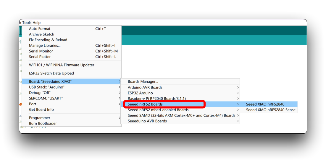
所有 XIAO 系列(XIAO nRF52840 系列除外)
本节适用于所有 XIAO(XIAO nRF52840 系列除外),这是一个用于读写文件的简单程序。
#include <SPI.h>
#include <SD.h>
#include <TFT_eSPI.h>

TFT_eSPI tft = TFT_eSPI();

File myFile;

void setup() {
  // Open serial communications and wait for port to open:
  Serial.begin(115200);
  while(!Serial);

  // Display initialization
  tft.init();

  Serial.print("Initializing SD card...");

  pinMode(D2, OUTPUT);
  if (!SD.begin(D2)) {
    Serial.println("initialization failed!");
    return;
  }
  Serial.println("initialization done.");

  // open the file. note that only one file can be open at a time,
  // so you have to close this one before opening another.
  myFile = SD.open("/test.txt", FILE_WRITE);

  // if the file opened okay, write to it:
  if (myFile) {
    Serial.print("Writing to test.txt...");
    myFile.println("testing 1, 2, 3.");
    // close the file:
    myFile.close();
    Serial.println("done.");
  } else {
    // if the file didn't open, print an error:
    Serial.println("error opening test.txt");
  }

  // re-open the file for reading:
  myFile = SD.open("/test.txt");
  if (myFile) {
    Serial.println("test.txt:");

    // read from the file until there's nothing else in it:
    while (myFile.available()) {
      Serial.write(myFile.read());
    }
    // close the file:
    myFile.close();
  } else {
    // if the file didn't open, print an error:
    Serial.println("error opening test.txt");
  }
}

void loop() {
  // nothing happens after setup
}
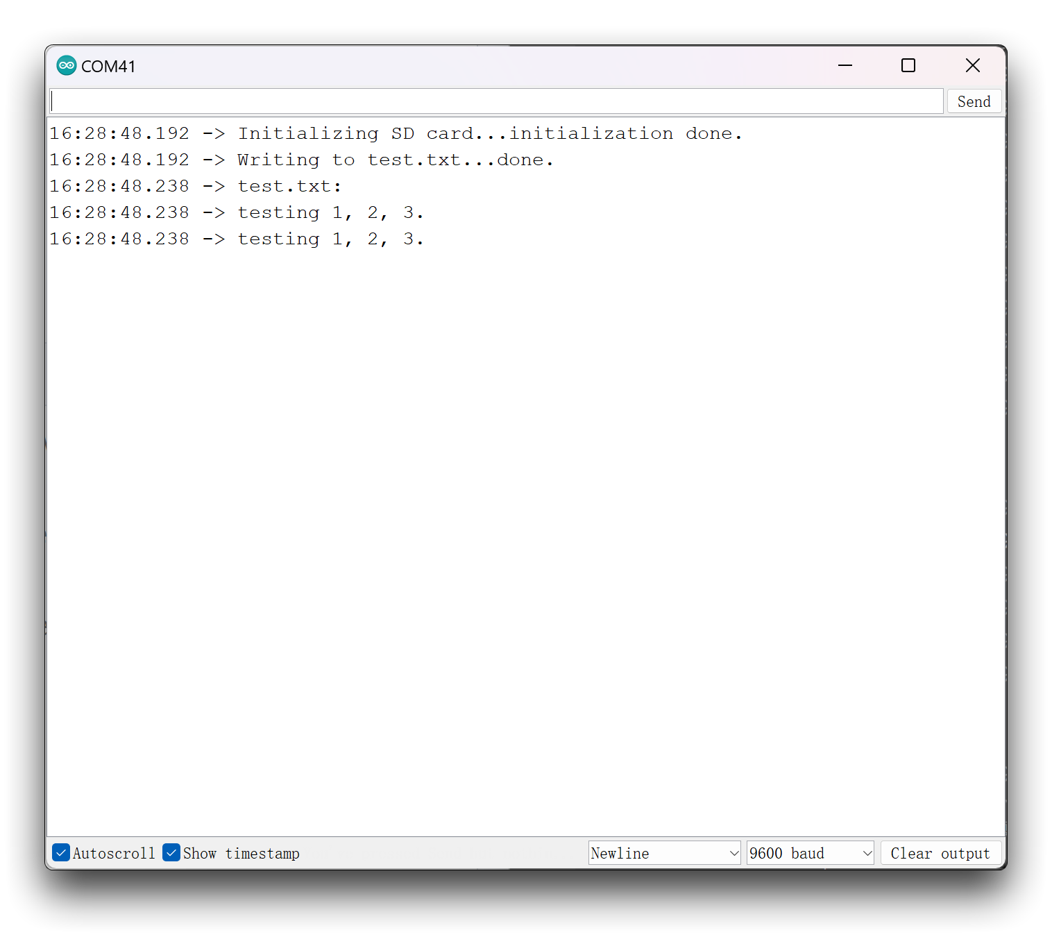
该程序会在你的 microSD 卡上创建一个名为 test.txt 的新文件,并写入 testing 1, 2, 3. 的内容。最后,它会读取该文件,并通过串口监视器打印出文件内容。
你会发现,在 SD 卡的程序中使用了屏幕 TFT 初始化。请不要认为这是无用的并可以删除,实际上在使用 SD 卡时这是必须的,否则你会收到 microSD 卡挂载失败的错误信息。
由于硬件设计的原因,部分引脚默认是低电平,这会导致 microSD 挂载程序认为没有上拉电阻,从而导致挂载失败。因此,在将 SD 卡功能与 Round Display 一起使用时,请务必在初始化 SD 卡之前先初始化屏幕显示。
XIAO nRF52840
如果你使用的是 XIAO nRF52840 系列,那么你可能需要单独下载 SdFat library 才能使用 SD 卡功能。
#include <SPI.h>
#include "SdFat.h"
#include <TFT_eSPI.h>

TFT_eSPI tft = TFT_eSPI();
SdFat SD;

#define SD_CS_PIN D2
File myFile;

void setup() {
  // Open serial communications and wait for port to open:
  Serial.begin(9600);
  while (!Serial) {
    ; // wait for serial port to connect. Needed for native USB port only
  }

  // Display initialization
  tft.init();

  Serial.print("Initializing SD card...");

  if (!SD.begin(SD_CS_PIN)) {
    Serial.println("initialization failed!");
    return;
  }
  Serial.println("initialization done.");

  // open the file. note that only one file can be open at a time,
  // so you have to close this one before opening another.
  myFile = SD.open("/test.txt", FILE_WRITE);

  // if the file opened okay, write to it:
  if (myFile) {
    Serial.print("Writing to test.txt...");
    myFile.println("testing 1, 2, 3.");
    // close the file:
    myFile.close();
    Serial.println("done.");
  } else {
    // if the file didn't open, print an error:
    Serial.println("error opening test.txt");
  }

  // re-open the file for reading:
  myFile = SD.open("test.txt");
  if (myFile) {
    Serial.println("test.txt:");

    // read from the file until there's nothing else in it:
    while (myFile.available()) {
      Serial.write(myFile.read());
    }
    // close the file:
    myFile.close();
  } else {
    // if the file didn't open, print an error:
    Serial.println("error opening test.txt");
  }
}

void loop() {
  // nothing happens after setup
}
XIAO ESP32S3 & XIAO ESP32S3 Sense & XIAO ESP32C3
由于 ESP32 系列具有非常强大的文件系统支持,我们为 XIAO ESP32 编写了一系列关于如何使用文件系统和保存 microSD 卡的示例,你可以通过下面的链接学习使用。
本 Wiki 中的教程适用于 XIAO ESP32 系列,但由于你现在要使用的是 Round Display 的 SD 卡槽,而上述教程主要侧重于使用 XIAO ESP32S3 Sense 上的 SD 卡槽,因此你需要将 SD 卡的初始化修改为下面这一行。
// Display initialization
tft.init();

pinMode(D2, OUTPUT);
SD.begin(D2);
不要忘记,你同样需要先初始化 TFT 屏幕才能使用 SD 卡功能。
屏幕功能
在屏幕的使用部分,主要分为触摸和显示两个核心功能模块。
触摸功能
触摸功能是 Round Display 的一大特色。你可以使用触摸功能来执行一些点按和长按的显示操作。
下面的程序可以用来输出显示屏是否被触摸的结果。
#define USE_TFT_ESPI_LIBRARY
#include "lv_xiao_round_screen.h"

void setup() {
  // put your setup code here, to run once:
  Serial.begin(115200);
  pinMode(TOUCH_INT, INPUT_PULLUP);
  Wire.begin();
}

void loop() {
  // put your main code here, to run repeatedly:
  if(chsc6x_is_pressed()){
    Serial.println("The display is touched.");
  }
  else
    Serial.println("The display is not touched.");
  delay(50);
}
下面的程序是一个将触摸功能与显示功能结合的简单示例。上传以下程序后,轻触屏幕,会在屏幕被点击的位置画出一个小圆点。
如果你使用的是 XIAO nRF52840,那么下面基于 TFT 库显示的程序可能无法正常工作,你需要修改程序以使用 Arduino GFX 库来完成显示。
#include <TFT_eSPI.h>
#include <SPI.h>
#define USE_TFT_ESPI_LIBRARY
#include "lv_xiao_round_screen.h"

lv_coord_t touchX, touchY;

void setup() {
  // put your setup code here, to run once:
  Serial.begin(115200);

  pinMode(TOUCH_INT, INPUT_PULLUP);
  Wire.begin();

  // Initialise the screen
  tft.init();

  tft.setRotation(0);
  tft.fillScreen(TFT_BLACK);
}

void loop() {
  // put your main code here, to run repeatedly:
  if(chsc6x_is_pressed())
  {
    Serial.println("The display is touched.");
    chsc6x_get_xy(&touchX, &touchY);
    tft.drawCircle(touchX, touchY, 15, TFT_WHITE);
  }

  delay(50);
}
显示功能
关于显示部分,我们主要介绍 LVGL 库和 TFT 库的使用。由于篇幅原因,我们会在新的 Wiki 中详细介绍如何使用所支持的图形库绘制复杂的表盘。
Using LVGL and TFT on the Seeed Studio Round Display for XIAO
当然,如果你只想实现一些简单的示例,这些图形库也提供了非常丰富的示例供你参考使用。
如果你已经安装了这些库,可以在 Arduino IDE 中通过 File->Example->library name 很方便地找到这些示例。

这里的示例仅供参考,并不是每一个示例都一定能直接运行。你可能需要修改程序以兼容 Round Display 的引脚分配和硬件定义。
技术支持与产品讨论
Q1:为什么我在使用 XIAO nRF52840(Sense)时会报错?
在使用本教程内容时,XIAO nRF52840 可能会出现两种不同类型的问题。
- nRF52840 与 TFT 库之间的兼容性问题。
如果你使用的是 TFT 库,编译和上传都没有任何错误,非常顺利。但在显示时,你会发现没有图像。那么你可能遇到了 nRF52840 与 TFT 库之间的兼容性问题。这意味着你只能更换 XIAO,或者使用 Arduino GFX 库来完成图像显示。
- 由于选择了错误的开发板而导致的编译错误。
如果你在编译过程中遇到问题,错误信息通常与 SPI 错误有关,例如 'SPI_X' was not declared in this scope。这就意味着你选择了错误类型的开发板。要使用本教程的全部内容,你需要使用 非 mbed 版本的 XIAO nRF52840。 -->
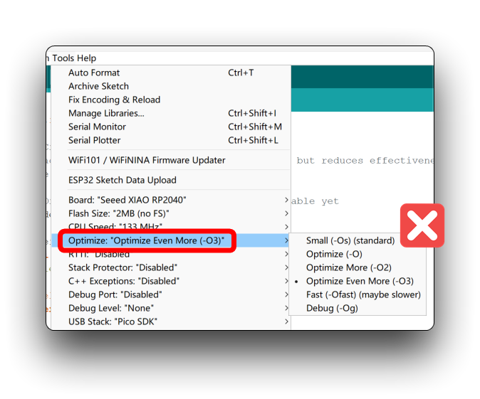
Q2:在为 XIAO RP2040 上传程序时出现错误:unaligned opcodes detected in executable segment?
请按照下图中的设置修改 XIAO RP2040 的上传选项。除了默认的 Small (-Os) (standard) 之外,其他所有选项都可以正常工作。
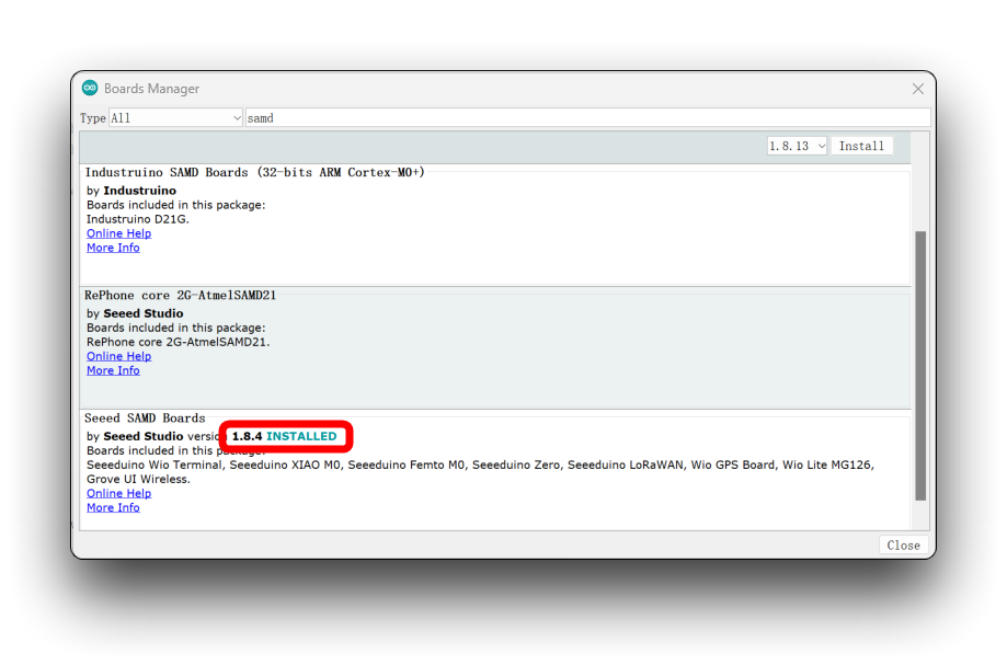
Q3:为什么在为 XIAO SAMD21 编译圆形屏幕程序时会出现引脚定义错误?
当你遇到此错误时,请将你的 Seeed SAMD 开发板板载包更新到最新版本。
Q4:为什么我将程序上传到 XIAO ESP32C3 后屏幕没有显示?
如果程序本身没有问题,但上传后仍然没有显示,可能是需要复位。只需按下 XIAO ESP32C3 上的复位按钮即可。
技术支持与产品讨论
感谢你选择我们的产品!我们将为你提供多种支持,以确保你在使用我们产品的过程中尽可能顺利。我们提供多种沟通渠道,以满足不同的偏好和需求。