连接到 SD 卡并挂载文件系统以支持 Seeed Studio XIAO。
本文档由 AI 翻译。如您发现内容有误或有改进建议,欢迎通过页面下方的评论区,或在以下 Issue 页面中告诉我们:https://github.com/Seeed-Studio/wiki-documents/issues
概述

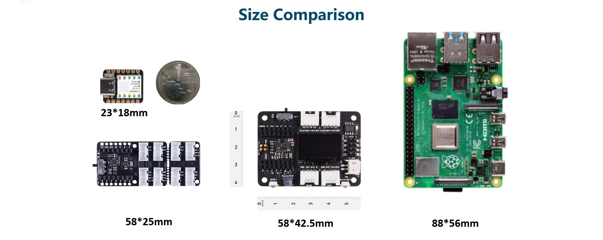
一款功能强大的扩展板,专为 Seeed Studio XIAO 设计,仅有半个 Raspberry Pi 4 的大小。它使得原型开发和项目构建变得简单快捷。通过其丰富的外设,包括 OLED、RTC、可扩展内存、无源蜂鸣器、RESET/用户按钮、5V伺服连接器、多种数据接口……您可以探索 Seeed Studio XIAO 的无限可能性。该扩展板还很好地支持 Circuitpython。
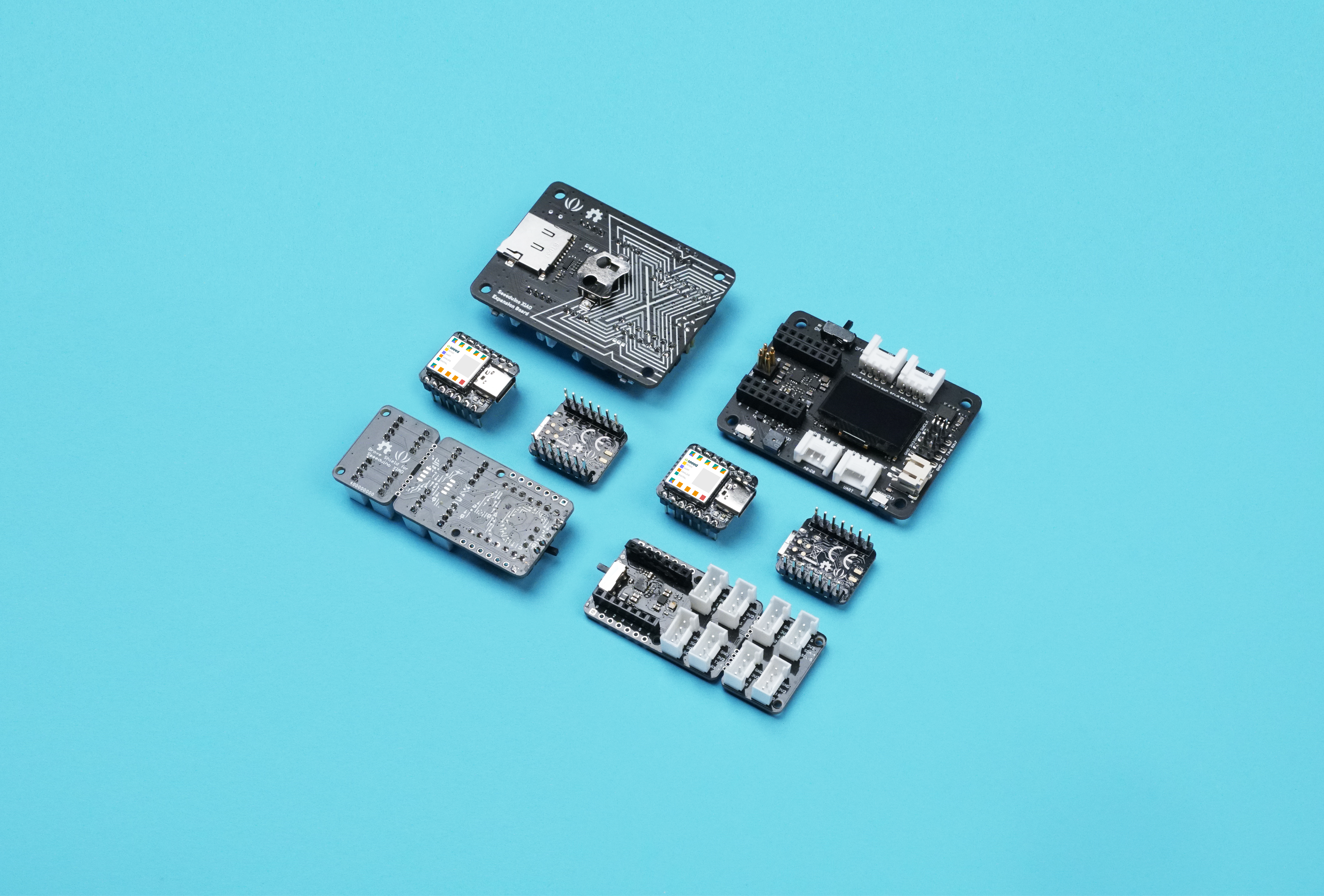
与 Seeed Studio XIAO 的外形尺寸一致,所有 Seeed Studio XIAO 板均支持 Grove Shield for Seeed Studio XIAO 和 Seeed Studio XIAO 扩展底座。两者的引脚略有不同,参考引脚图即可轻松管理。
Seeed Studio XIAO SAMD21、Seeed Studio XIAO RP2040 和 Seeed Studio XIAO nRF52840 均兼容 Seeed Studio XIAO 扩展底座。
特性
- 快速原型开发: 通过 RESET 按钮和引出的 SWD 引脚轻松调试和复位。
- 丰富的外设: OLED 显示屏、RTC、可扩展内存空间、无源蜂鸣器、用户按钮、板载电池管理芯片。
- 无需焊接: 所有引脚均已引出。方便的即插即用 Grove 接口支持多种数据协议,包括 IIC、UART、模拟/数字。
- 支持 Circuit Python: 完美支持 Circuit Python。MicroSD 卡插槽可扩展内存空间,使得在原型开发和项目构建中分配更多所需的库成为可能。
- 迷你尺寸: 紧凑优雅,仅有半个 Raspberry Pi 4 的大小,特别适合需要小尺寸的项目。
规格
| 项目 | 参数 |
|---|---|
| 工作电压 | 5V / 3.7V 锂电池 |
| 充电电流 | 460mA (最大) |
| RTC 定时器精度 | ± 1.5S/天 (25°C) |
| RTC 电池 | CR1220 |
| 显示屏 | 0.96" OLED 显示屏 |
| 可扩展内存 | MicroSD 卡 |
| Grove 接口 | Grove IIC*2, Grove UART*1, A0/D0 Grove*1 |
| 其他外部设备 | 无源蜂鸣器、用户按钮、5V 伺服连接器 |
应用场景
- SWD 调试
- 快速原型开发
- 数据显示
- 小型项目
包装清单
| 项目 | 数量 |
|---|---|
| Seeed Studio XIAO 扩展底座 | *1 |
此产品不包含 Seeed Studio XIAO 和电池。Seeed Studio XIAO 系列正在不断推出新产品。要了解该系列的最新产品开发,请访问 XIAO 系列主页。
入门指南
所需材料
| Seeed Studio XIAO SAMD21 (预焊接) | Seeed Studio XIAO 扩展底座 |
|---|---|
|
|
| 立即购买 | 立即购买 |

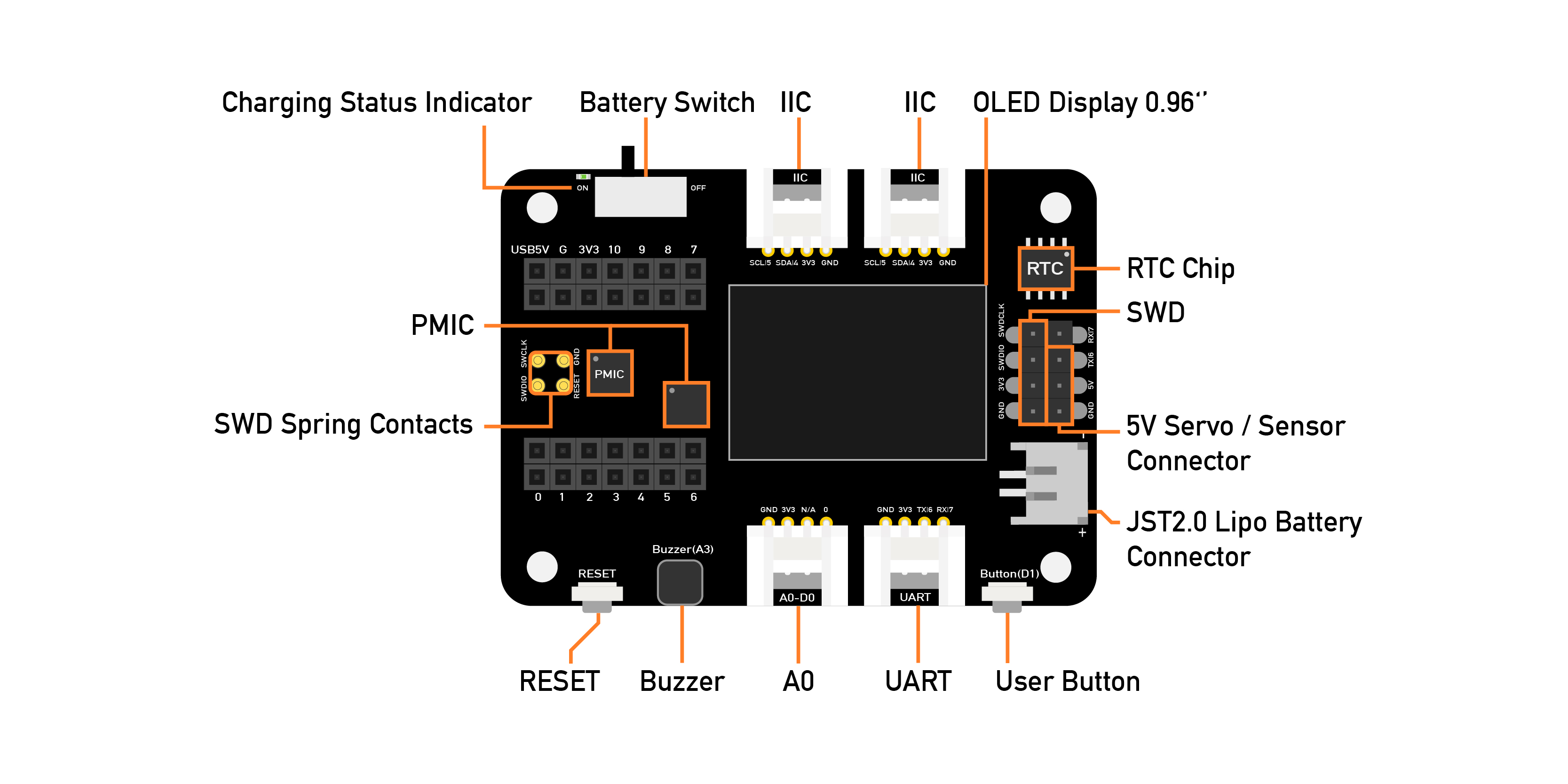
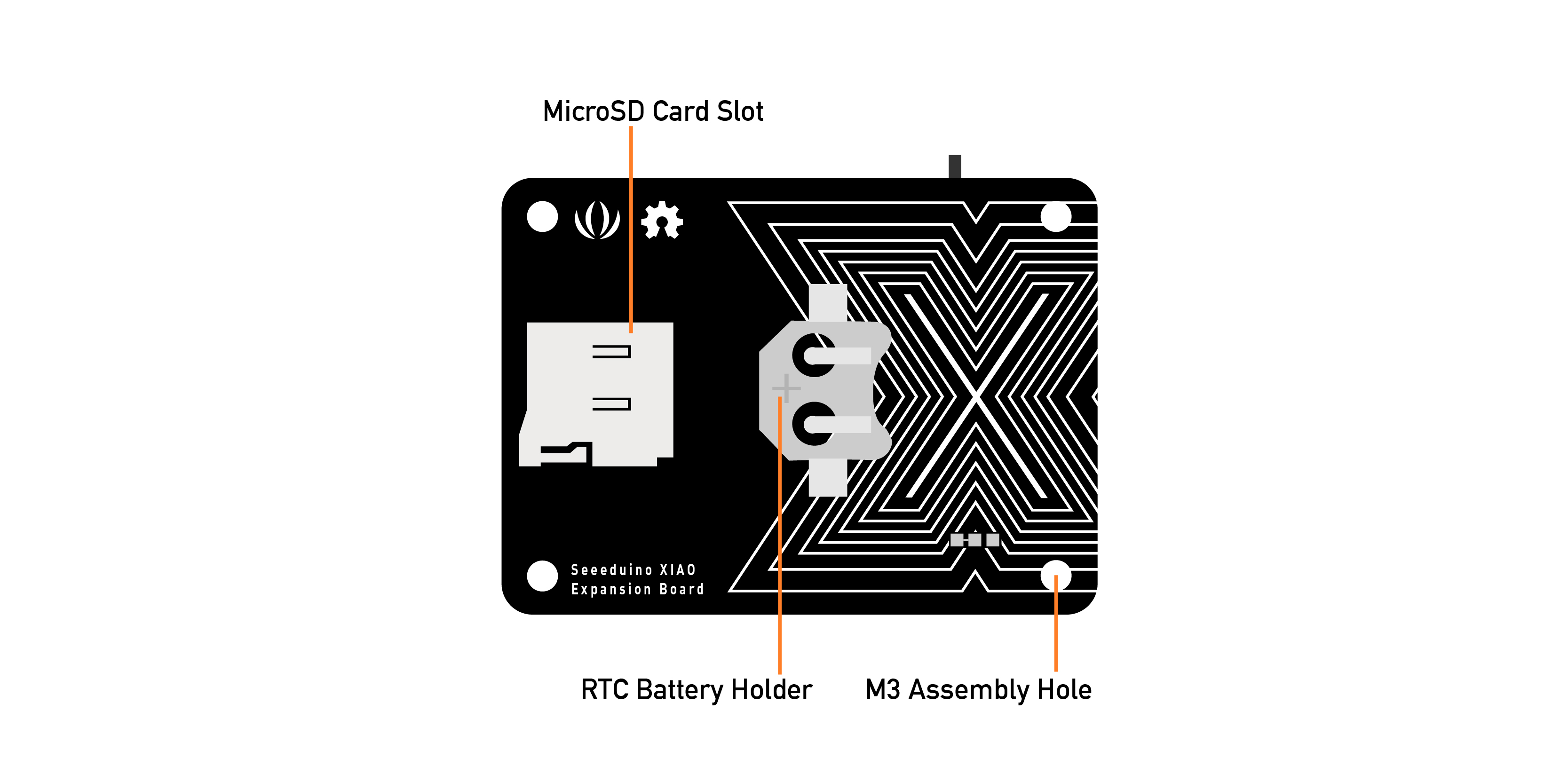
硬件概览
扩展板上有一个外部 MicroSD 卡插槽和 RTC 电池座。MicroSD 卡主要用于保存和运行 python.py 文件,而 RTC 用于跟踪当前时间,可用于在特定时间编程执行操作。
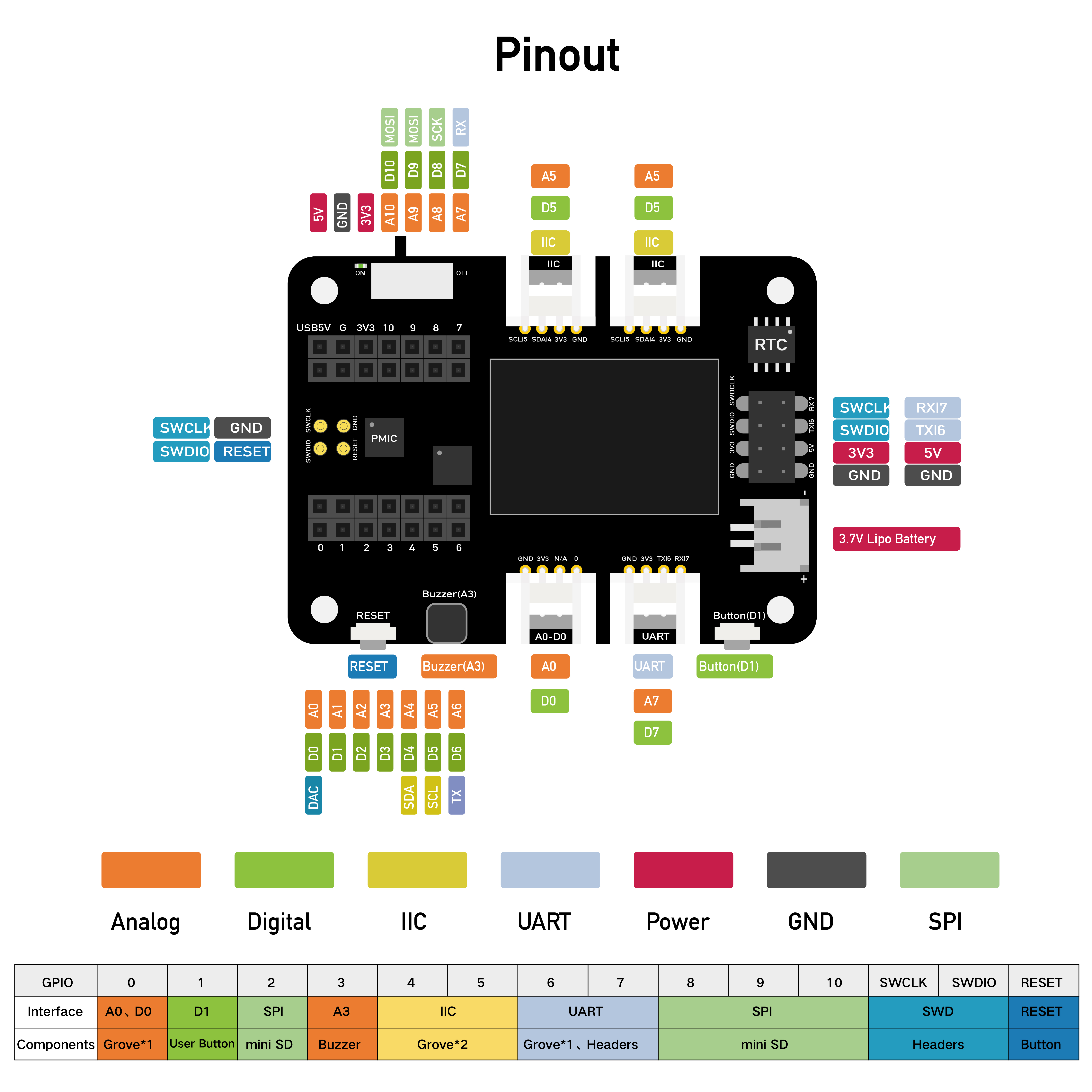
引脚图
Grove-Shield for Seeed Studio XIAO 的外部引脚描述。
扩展板使用方法
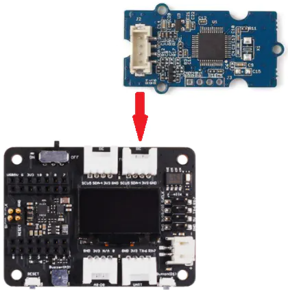
连接
将 Seeed Studio XIAO SAMD21 插入扩展板,Seeed Studio XIAO SAMD21 的绿色 LED 应该会亮起。
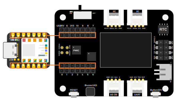
请先将 Seeed Studio XIAO 插入扩展板,然后再插入 Type-C 接口。请确保将 Seeed Studio XIAO 插入 两个母头连接器的中间位置,否则可能会损坏 Seeed Studio XIAO 和扩展板。
电池使用
Seeed Studio 的 XIAO 扩展基板可以通过电池供电,因此如果您需要进行一些需要移动的演示,电池将帮助您解决电源问题。在插入电池时,请注意正负极,按照图片连接电池以避免损坏电路板。
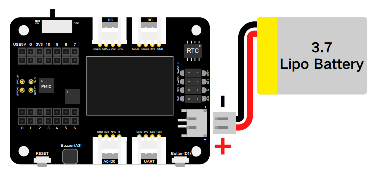
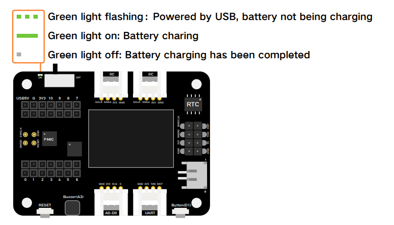
此外,当您插入电池线缆和 Type-C 线缆并将开关拨到开启状态时,电路板会为电池充电。
如下面的图片所示,如果 LED 闪烁,这意味着电池未充电或电路板未连接电池;如果 LED 常亮,这意味着电池正在充电。
扩展板上的模块
扩展板上丰富的外设包括:
OLED 显示屏: 无需连接到 PC 即可进行数据可视化显示,这使调试更加高效,并可构建诸如传感器集线器、数据监控系统等应用。
RESET 按钮: 不再需要跳线和短路,只需轻轻一按即可轻松复位。
SWD 调试: SWD 引脚以公针形式引出,使调试器连接和固件下载更加方便。
高精度 RTC: 带电池备份的高精度实时时钟,主电源关闭时仍能保持准确时间。
可扩展存储: 背面配备 MicroSD 卡插槽,添加库和使用 Circuit Python 时不再担心存储限制。
用户按钮: 除 RESET 按钮外,还提供另一个用户自定义按钮。
无源蜂鸣器: 您可以更改 PWM 频率以产生不同的蜂鸣声,从而获得“蜂鸣器音乐”。
Grove 接口: 所有引脚均引出,支持即插即用的 Grove 接口,兼容常见数据协议(Grove IIC2、Grove UART1、A0/D0 Grove*1)。
锂电池充电: JST2.0mm 标准锂电池连接器和电池管理系统,支持 USB 和锂电池供电,并可轻松进行板载电池充电。
5V 舵机连接器: 5V 输出以公针形式引出,用于连接 5V 舵机和传感器。

OLED 显示屏
本示例介绍如何使用 Seeed Studio 的 XIAO 扩展基板上的 OLED 显示屏。
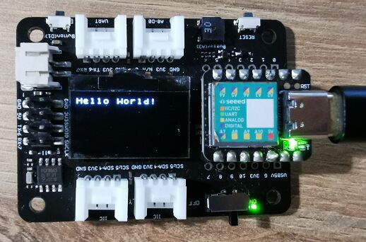
步骤 1. 将 Seeed Studio XIAO SAMD21 安装到扩展板上,然后连接 Type-C 线缆。
步骤 2. 安装 u8g2 库,以下是 如何安装库 的指南。
步骤 3. 复制代码并粘贴到 Arduino IDE 中,然后上传。
OLED 代码
#include <Arduino.h>
#include <U8x8lib.h>
#include <Wire.h>

// OLED 显示屏初始化,无需复位引脚
U8X8_SSD1306_128X64_NONAME_HW_I2C u8x8(/* clock=*/ SCL, /* data=*/ SDA, /* reset=*/ U8X8_PIN_NONE);

void setup(void) {
  u8x8.begin();
  u8x8.setFlipMode(1);   // 设置屏幕翻转模式,数字范围为 1 到 3,屏幕文字将旋转 180 度
}

void loop(void) {
  u8x8.setFont(u8x8_font_chroma48medium8_r);
  u8x8.setCursor(0, 0);
  u8x8.print("Hello World!"); // 显示 "Hello World!"
}
使用用户按钮控制 LED
本示例介绍如何使用 Seeed Studio 的 XIAO 扩展基板上的按钮来控制 Seeed Studio XIAO SAMD21 上的 LED。
步骤 1. 将 Seeed Studio XIAO SAMD21 安装到扩展板上,然后连接 Type-C 线缆。
步骤 2. 打开 Arduino IDE,复制代码并粘贴到 Arduino IDE 中,然后上传。
代码
const int buttonPin = 1;     // 按钮引脚编号
int buttonState = 0;         // 用于读取按钮状态的变量

void setup() {
  // 初始化 LED 引脚为输出模式
  pinMode(LED_BUILTIN, OUTPUT);
  // 初始化按钮引脚为输入模式,并启用内部上拉电阻
  pinMode(buttonPin, INPUT_PULLUP);
}

void loop() {
  // 读取按钮状态
  buttonState = digitalRead(buttonPin);

  // 检查按钮是否被按下。如果按下,buttonState 为 HIGH
  if (buttonState == HIGH) {
    // 打开 LED
    digitalWrite(LED_BUILTIN, HIGH);
  } else {
    // 关闭 LED
    digitalWrite(LED_BUILTIN, LOW);
  }
}
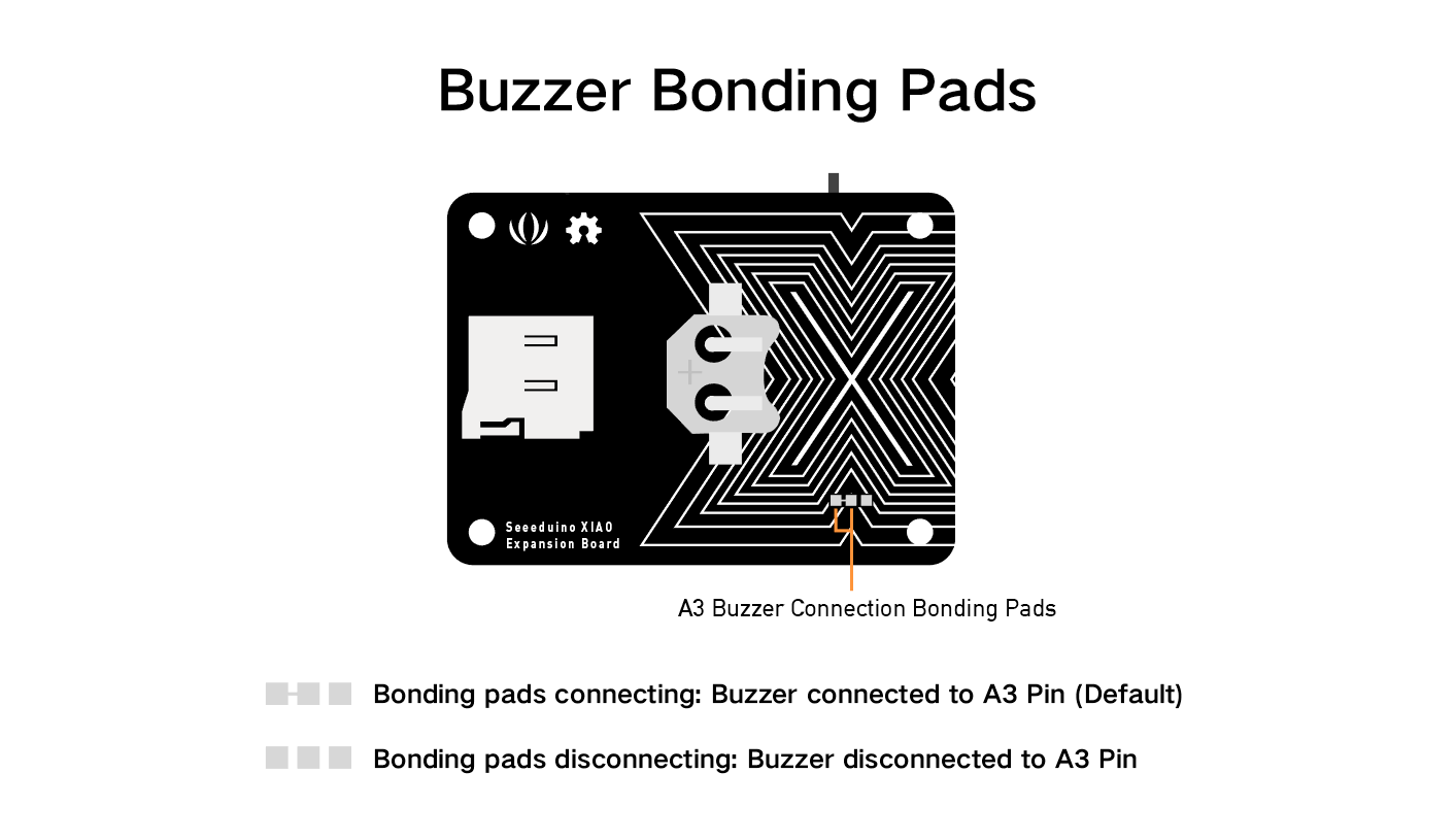
蜂鸣器
蜂鸣器默认连接到引脚 A3,如果您想移除蜂鸣器功能,只需按照下图所示切断线路。
使用无源蜂鸣器播放歌曲
本示例使用 Seeed Studio 的 XIAO 扩展基板上的蜂鸣器播放《生日快乐》。
步骤 1. 将 Seeed Studio XIAO SAMD21 安装到扩展板上,然后连接 Type-C 线缆。
步骤 2. 打开 Arduino IDE,复制代码并粘贴到 Arduino IDE 中,然后上传。
代码
int speakerPin = D3; // 蜂鸣器连接的引脚
int length = 28; // 音符数量
char notes[] = "GGAGcB GGAGdc GGxecBA yyecdc"; // 音符序列
int beats[] = { 2, 2, 8, 8, 8, 16, 1, 2, 2, 8, 8, 8, 16, 1, 2, 2, 8, 8, 8, 8, 16, 1, 2, 2, 8, 8, 8, 16 }; // 每个音符的节拍
int tempo = 150; // 节奏速度

void playTone(int tone, int duration) {
  for (long i = 0; i < duration * 1000L; i += tone * 2) {
    digitalWrite(speakerPin, HIGH);
    delayMicroseconds(tone);
    digitalWrite(speakerPin, LOW);
    delayMicroseconds(tone);
  }
}

void playNote(char note, int duration) {
  char names[] = {'C', 'D', 'E', 'F', 'G', 'A', 'B',
                  'c', 'd', 'e', 'f', 'g', 'a', 'b',
                  'x', 'y'
                 };
  int tones[] = { 1915, 1700, 1519, 1432, 1275, 1136, 1014,
                  956,  834,  765,  593,  468,  346,  224,
                  655 , 715
                };
  int SPEE = 5;

  // 播放对应音符的音调
  for (int i = 0; i < 16; i++) {
    if (names[i] == note) {
      int newduration = duration / SPEE;
      playTone(tones[i], newduration);
    }
  }
}

void setup() {
  pinMode(speakerPin, OUTPUT); // 设置蜂鸣器引脚为输出模式
}

void loop() {
  for (int i = 0; i < length; i++) {
    if (notes[i] == ' ') {
      delay(beats[i] * tempo); // 休止符
    } else {
      playNote(notes[i], beats[i] * tempo); // 播放音符
    }
    // 音符之间的暂停
    delay(tempo);
  }
}
使用旋转角度传感器控制舵机
本示例使用旋转角度传感器通过 Seeed Studio 扩展基板上的集成端口控制舵机。
步骤 1. 将 Seeed Studio XIAO SAMD21 安装到扩展板上,然后连接 Type-C 数据线。
步骤 2. 将舵机电缆连接到 I2C 端口,旋转角度传感器连接到 D0。
步骤 3. 打开 Arduino IDE,复制以下代码并粘贴到 Arduino IDE 中,然后上传代码。
如果您的开发板是 XIAO ESP32 系列,在运行以下代码之前,您需要先在 Arduino Library Manager 中安装 ESP32Servo 库,并将代码中的 #include <Servo.h> 替换为 #include <ESP32Servo.h>。
#include <Servo.h>
#include <Arduino.h>
#include <Wire.h>

#define ROTARY_ANGLE_SENSOR A0
#define ADC_REF 3 // ADC 的参考电压为 3V。如果 Seeeduino 上的 Vcc 开关打开
#define GROVE_VCC 3 // Grove 接口的 VCC 通常为 3V
#define FULL_ANGLE 300 // 旋转角度的最大值为 300 度

Servo myservo;  // 创建一个舵机对象以控制舵机
// 大多数板子上可以创建 12 个舵机对象

int pos = 0;    // 用于存储舵机位置的变量

void setup() {
  Serial.begin(9600);
  pinMode(ROTARY_ANGLE_SENSOR, INPUT);
  myservo.attach(5);  // 将舵机连接到引脚 5
}

void loop() {

  float voltage;
  int sensor_value = analogRead(ROTARY_ANGLE_SENSOR);
  voltage = (float)sensor_value * ADC_REF / 1023;
  float degrees = (voltage * FULL_ANGLE) / GROVE_VCC;
  Serial.println("标记与起始位置之间的角度:");
  Serial.println(degrees);
  delay(50);
  myservo.write(degrees);
}
RTC 时钟显示
本示例使用 RTC 在 OLED 上显示时钟。
步骤 1. 将 Seeed Studio XIAO SAMD21 安装到扩展板上,然后连接 Type-C 数据线。
步骤 2. 安装 u8g2 和 PCF8563 库,参考指南 如何安装库。
步骤 3. 复制以下代码并粘贴到 Arduino IDE 中,然后上传代码。
#include <Arduino.h>
#include <U8x8lib.h>
#include <PCF8563.h>
PCF8563 pcf;
#include <Wire.h>

U8X8_SSD1306_128X64_NONAME_HW_I2C u8x8(/* clock=*/ SCL, /* data=*/ SDA, /* reset=*/ U8X8_PIN_NONE);   // 无复位引脚的 OLED 显示屏

void setup() {
  Serial.begin(115200);
  u8x8.begin();
  u8x8.setFlipMode(1);
  Wire.begin();
  pcf.init(); // 初始化时钟
  pcf.stopClock(); // 停止时钟
  pcf.setYear(20); // 设置年份
  pcf.setMonth(10); // 设置月份
  pcf.setDay(23); // 设置日期
  pcf.setHour(17); // 设置小时
  pcf.setMinut(33); // 设置分钟
  pcf.setSecond(0); // 设置秒
  pcf.startClock(); // 启动时钟
}

void loop() {
  Time nowTime = pcf.getTime(); // 获取当前时间
  u8x8.setFont(u8x8_font_chroma48medium8_r);   // 选择合适的字体

  u8x8.setCursor(0, 0);
  u8x8.print(nowTime.day);
  u8x8.print("/");
  u8x8.print(nowTime.month);
  u8x8.print("/");
  u8x8.print("20");
  u8x8.print(nowTime.year);
  u8x8.setCursor(0, 1);
  u8x8.print(nowTime.hour);
  u8x8.print(":");
  u8x8.print(nowTime.minute);
  u8x8.print(":");
  u8x8.println(nowTime.second);
  delay(1000);
}
SD 卡功能
对于 XIAO SAMD21、XIAO RP2040、XIAO ESP32C3 和 XIAO ESP32S3,您无需安装第三方 SD 卡库即可使用。以下步骤适用于这些 XIAO。
扩展板电路设计中,SD 卡槽的 CS 引脚连接到 XIAO 的 D2 引脚。
#include <SPI.h>
#include <SD.h>
#include "FS.h"

File myFile;

void setup() {
  // 打开串口通信并等待端口打开:
  Serial.begin(115200);
  while(!Serial);              // 打开串口监视器后执行
  delay(500);

  Serial.print("正在初始化 SD 卡...");

  pinMode(D2, OUTPUT);          // 修改此处的引脚以适配您使用的 SD 卡 CS 引脚
  if (!SD.begin(D2)) {
    Serial.println("初始化失败!");
    return;
  }
  Serial.println("初始化完成。");

  // 打开文件。注意一次只能打开一个文件,
  // 因此在打开另一个文件之前需要关闭当前文件。
  myFile = SD.open("/test.txt", FILE_WRITE);          // 读写文件的路径需要以 "/" 开头

  // 如果文件成功打开,写入内容:
  if (myFile) {
    Serial.print("正在写入 test.txt...");
    myFile.println("测试 1, 2, 3.");
    // 关闭文件:
    myFile.close();
    Serial.println("完成。");
  } else {
    // 如果文件未能打开,打印错误信息:
    Serial.println("打开 test.txt 时出错");
  }

  // 重新打开文件以读取:
  myFile = SD.open("/test.txt");                       // 读写文件的路径需要以 "/" 开头
  if (myFile) {
    Serial.println("test.txt:");

    // 从文件中读取内容直到没有内容为止:
    while (myFile.available()) {
      Serial.write(myFile.read());
    }
    // 关闭文件:
    myFile.close();
  } else {
    // 如果文件未能打开,打印错误信息:
    Serial.println("打开 test.txt 时出错");
  }
}

void loop() {
  // setup 之后无操作
}
如果您使用的是 XIAO nRF52840 系列,则可能需要单独下载 SdFat 库 以使用 SD 卡功能。
#include <SPI.h>
#include "SdFat.h"
SdFat SD;

#define SD_CS_PIN D2
File myFile;

void setup() {
  // 打开串口通信并等待端口打开:
  Serial.begin(9600);
  while (!Serial) {
    ; // 等待串口连接,仅适用于原生 USB 端口
  }

  Serial.print("正在初始化 SD 卡...");

  if (!SD.begin(SD_CS_PIN)) {
    Serial.println("初始化失败!");
    return;
  }
  Serial.println("初始化完成。");

  // 打开文件。注意一次只能打开一个文件,
  // 因此在打开另一个文件之前需要关闭当前文件。
  myFile = SD.open("/test.txt", FILE_WRITE);

  // 如果文件成功打开,写入内容:
  if (myFile) {
    Serial.print("正在写入 test.txt...");
    myFile.println("测试 1, 2, 3.");
    // 关闭文件:
    myFile.close();
    Serial.println("完成。");
  } else {
    // 如果文件未能打开,打印错误信息:
    Serial.println("打开 test.txt 时出错");
  }

  // 重新打开文件以读取:
  myFile = SD.open("test.txt");
  if (myFile) {
    Serial.println("test.txt:");

    // 从文件中读取内容直到没有内容为止:
    while (myFile.available()) {
      Serial.write(myFile.read());
    }
    // 关闭文件:
    myFile.close();
  } else {
    // 如果文件未能打开,打印错误信息:
    Serial.println("打开 test.txt 时出错");
  }
}

void loop() {
  // setup 之后无操作
}
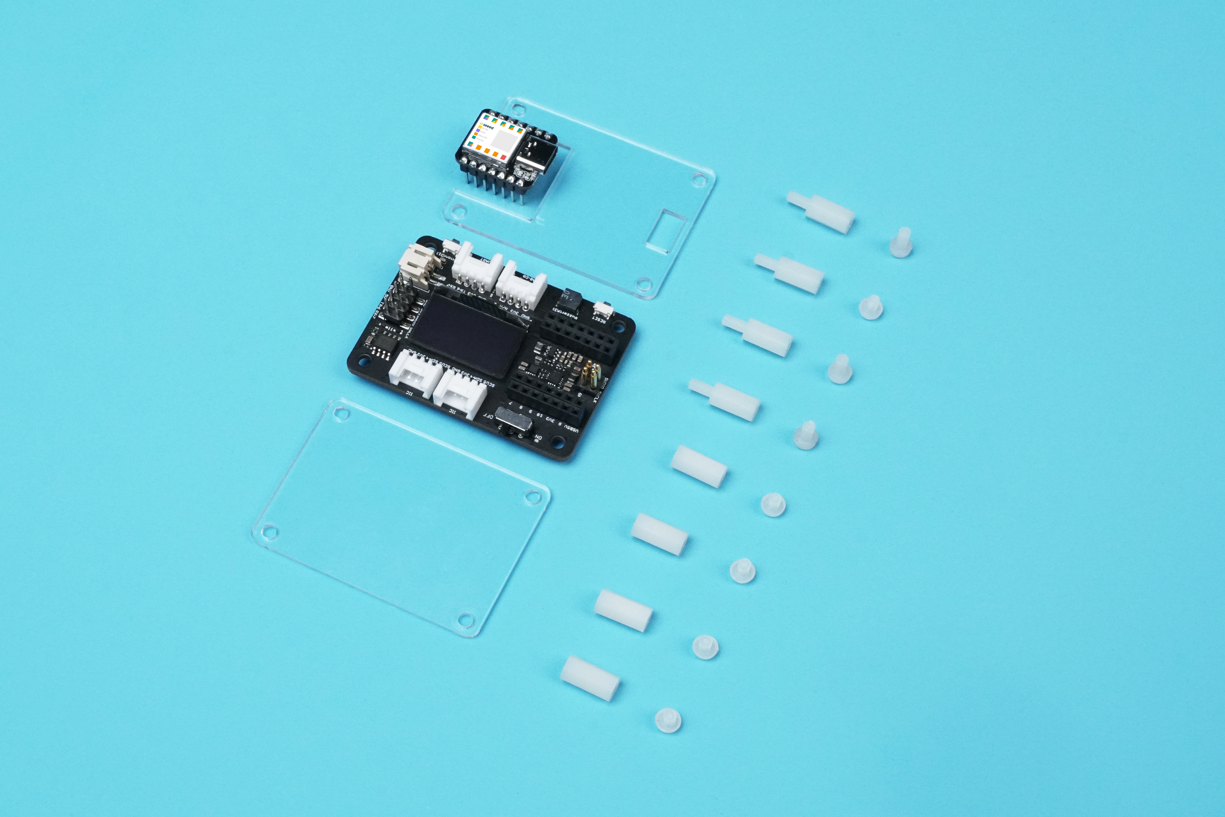
Seeed Studio XIAO 扩展基座的亚克力外壳
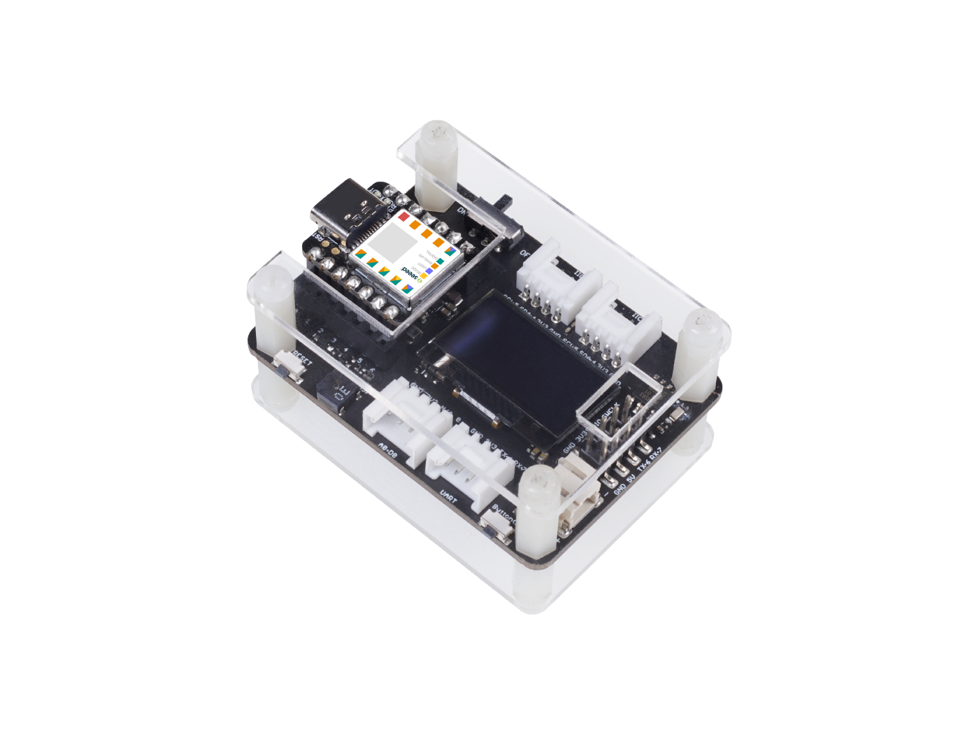

我们为 Seeed Studio XIAO 扩展基座设计了这个 亚克力外壳,以下是亚克力外壳的组件。
与 Seeed Studio XIAO 的 Grove Shield 相比,Seeed Studio XIAO 扩展基座为用户增加了许多实用模块。
这个亚克力外壳易于组装,同时也能让外壳看起来更加整洁。

在 Seeed Studio XIAO SAMD21 扩展板上运行 CircuitPython
本教程介绍如何在 Seeed Studio XIAO SAMD21 开发板 上安装并运行 Adafruit Industries 官方的 CircuitPython!
CircuitPython 是一种编程语言,旨在简化在低成本微控制器板上进行实验和学习编程的过程。它使入门变得前所未有的简单,无需预先下载桌面软件。设置好开发板后,只需打开任何文本编辑器即可开始编辑代码。更多信息请参考 这里。
安装 CircuitPython
步骤 1. 将 Seeed Studio XIAO SAMD21 安装到扩展板上,然后连接 Type-C 数据线。
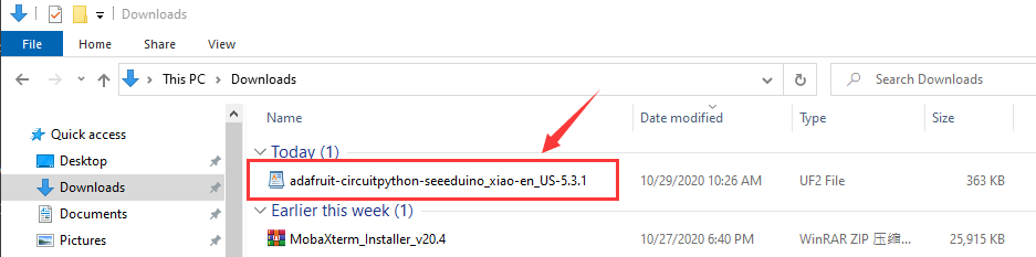
步骤 2. 下载官方的 Seeed Studio XIAO SAMD21 的 CircuitPython Bootloader。一个 .uf2 文件会存储在你的电脑下载目录中。
步骤 3. 快速按两次 Seeed Studio XIAO 扩展基座上的复位按钮,进入 DFU 引导模式,此时你的电脑会显示 Arduino 驱动。
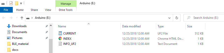
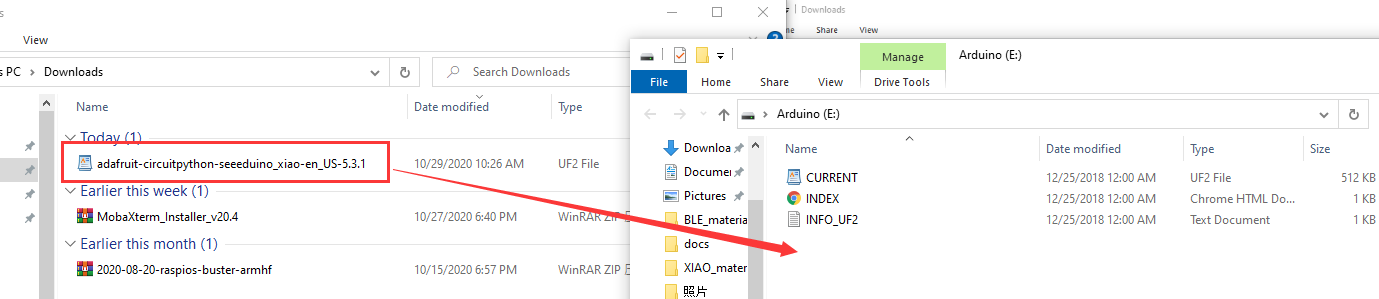
步骤 4. 你的电脑上会出现一个名为 Arduino 的外部驱动器。将下载的 CircuitPython .uf2 文件拖到 Arduino 驱动器中。
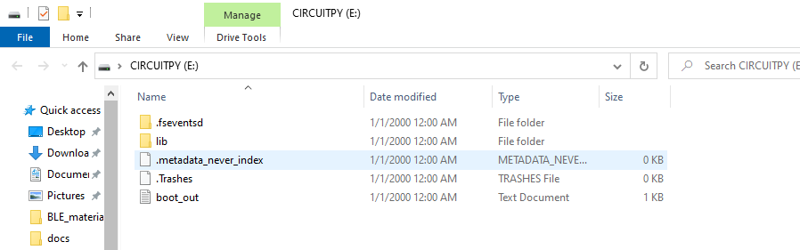
步骤 5. 加载 CircuitPython Bootloader 后,拔下 USB Type-C 数据线并重新连接。此时会出现一个名为 CIRCUITPY 的新外部驱动器。
步骤 6. 现在,CircuitPython 已加载到 Seeed Studio XIAO SAMD21 上!你只需编写 Python 程序,将其命名为 main.py,然后将其拖到 CIRCUITPY 驱动器中即可。
CircuitPython 闪烁示例
以下是一个简单的示例,介绍如何在 Seeed Studio XIAO 上使用 CircuitPython。
步骤 1 在 CIRCUITPY 驱动器上创建一个名为 main 的文本文件。
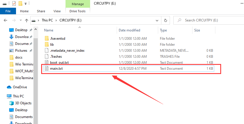
main 文件名可以是以下之一:code.txt、code.py、main.py、main.txt。有关更多详细信息,请参考 此行为。
步骤 2 使用 REPL 获取橙色 LED 的引脚。有关 REPL 的详细信息,请参阅 欢迎使用 CircuitPython!。要使用 REPL,首先需要连接到串行控制台。连接建立后,按两次 CTRL+C 进入编辑模式。然后,分别复制并输入以下代码:
>>> import board
>>> dir(board)
你会看到开发板上所有可供代码使用的引脚列表。每块开发板的引脚数量可能略有不同。

你是否看到了 YELLOW_LED_INVERTED?这就是用于控制橙色 LED 闪烁的引脚!
步骤 3 将以下代码粘贴到 main 文件中并保存,你会看到橙色 LED 在 Seeed Studio XIAO SAMD21 板上闪烁。
代码
import time
import board
from digitalio import DigitalInOut, Direction

led = DigitalInOut(board.YELLOW_LED_INVERTED)
led.direction = Direction.OUTPUT

while True:
    led.value = True
    time.sleep(1)
    led.value = False
    time.sleep(1)
使用 MicroSD 卡运行 CircuitPython
Seeed Studio XIAO SAMD21 内置约 40 KB 的闪存,但可能不足以存储较大的 Python 代码文件。幸运的是,Seeed Studio XIAO SAMD21 扩展板内置了一个 MicroSD 卡插槽,用于扩展存储空间。你可以按照以下说明学习如何在 MicroSD 卡上运行 CircuitPython。
MicroSD 卡的文件系统格式必须为 FAT 或 exFAT。如果使用其他文件系统格式,MicroSD 卡将无法被识别。
步骤 1. 准备一张 MicroSD 卡并插入 Seeed Studio XIAO SAMD21 扩展板。
步骤 2. 如果尚未下载 CircuitPython 文件,请参考 安装 CircuitPython 章节。
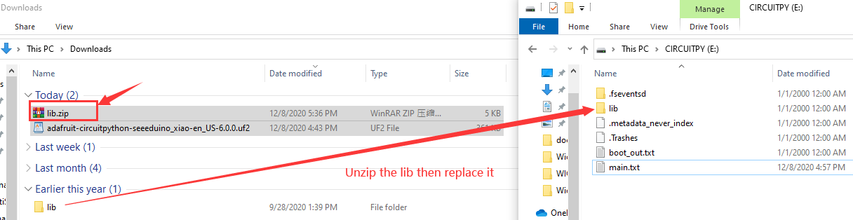
步骤 3. 下载 lib,解压文件,然后将其替换为 CIRCUITPY 中的新 lib。
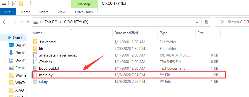
步骤 4. 下载 main.py 文件到 CIRCUITPY 驱动器中。
main.py 代码
import sd
f = open("/sd/hello.txt", "r")   ## 从 SD 卡读取文件
print(f.read())
步骤 5. 下载 sd.py 文件到 CIRCUITPY 驱动器中。
sd.py 代码
import os
import adafruit_sdcard
import board
import busio
import digitalio
import storage
import sys

spi = busio.SPI(board.SCK, board.MOSI, board.MISO)
cs = digitalio.DigitalInOut(board.D2)
sdcard = adafruit_sdcard.SDCard(spi, cs)
vfs = storage.VfsFat(sdcard)
storage.mount(vfs, "/sd")
sys.path.append("/sd")
sys.path.append("/sd/lib")  ## 切换到 SD 卡路径
蜂鸣器示例
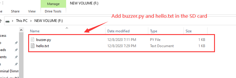
此示例通过运行 MicroSD 卡中的 buzzer.py 测试蜂鸣器。
步骤 1. 将 buzzer.py 粘贴到 MicroSD 卡中。
步骤 2. 打开 main.py 文件位于 CIRCUITPY 驱动器中。
步骤 3. 在 main.py 文件中添加 import buzzer。
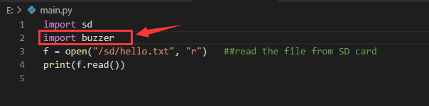
完成所有步骤后,蜂鸣器将开始工作。如果需要运行 MicroSD 卡中的其他 Python 文件,请模仿此示例。
如果您想切换回 Arduino 模式,只需在 Arduino IDE 上上传任何程序即可。
演示
项目 1 - 遥控风扇
概述
本教程介绍如何制作一个迷你风扇放置在房间中以保持凉爽。
特点
- 自动摆动风扇
所需组件
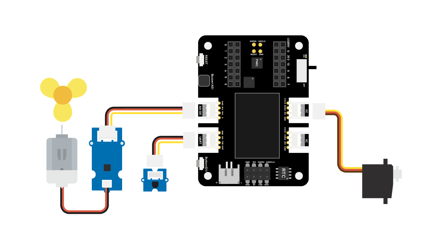
硬件连接
请按照相同颜色的线连接每个传感器到扩展板上。请将风扇的 Grove 电缆连接到 D0,将舵机的 Grove 电缆连接到 I2C,将红外接收器的 Grove 电缆连接到 D7。
Arduino 指南
步骤 1. 按照连接图连接所有传感器到扩展板上。
步骤 2. 安装 Arduino-IRremote 库,以下是指南 如何安装库。
步骤 3. 将代码复制到 Arduino IDE 中并上传。
步骤 4. 将风扇放置在安全位置,尝试按下按钮确保其可以安全工作。
代码
#include <IRremote.h>
#include <Servo.h>

Servo myservo;  // 创建舵机对象以控制舵机
int RECV_PIN = 7; // 设置引脚 7 为红外控制

IRrecv irrecv(RECV_PIN);

decode_results results;

int pos = 90;    // 用于存储舵机位置的变量
int fanPin = 0;  // 设置 D0 为控制开关
int fanState = LOW;
int IO = 0;

void setup()
{
  Serial.begin(9600);
  Serial.println("启用 IRin");  // 提示启用红外
  irrecv.enableIRIn(); // 启动接收器
  Serial.println("已启用 IRin");
  myservo.attach(5);  // 将舵机连接到引脚 5
  pinMode(fanPin, OUTPUT);

}

void loop() {
  if (irrecv.decode(&results)) { // 检查红外信号
    if (results.value == 2155829415) {    // 开关风扇
      IO++;
      if (IO % 2 == 0) {
        fanState = HIGH;
        digitalWrite(fanPin, fanState);
        delay(100);
      }
      else {
        fanState = LOW;
        digitalWrite(fanPin, fanState);
        delay(100);
      }
    }

    if (results.value == 2155821255 ) {    // 风扇向左摆动
      for (pos; pos <= 89; pos += 1) { // 从 0 度到 90 度
        myservo.write(pos);              // 告诉舵机移动到变量 'pos' 的位置
        delay(40);                       // 等待舵机到达位置
        if (irrecv.decode(&results)) {
          irrecv.resume();
          if (results.value == 2155870215)
            break;
        }
      }
    }

    if (results.value == 2155870215 ) {    // 风扇向右摆动
      for (pos; pos >= 1; pos -= 1) { // 从 90 度到 0 度
        myservo.write(pos);              // 告诉舵机移动到变量 'pos' 的位置
        delay(40);                       // 等待舵机到达位置
        if (irrecv.decode(&results)) {
          irrecv.resume();
          if (results.value == 2155821255)
            break;
        }
      }
    }
    Serial.println(pos);
    Serial.println(results.value, HEX);
    Serial.println(results.value);
    irrecv.resume();                    // 接收下一个指令
  }
  delay(100);
}
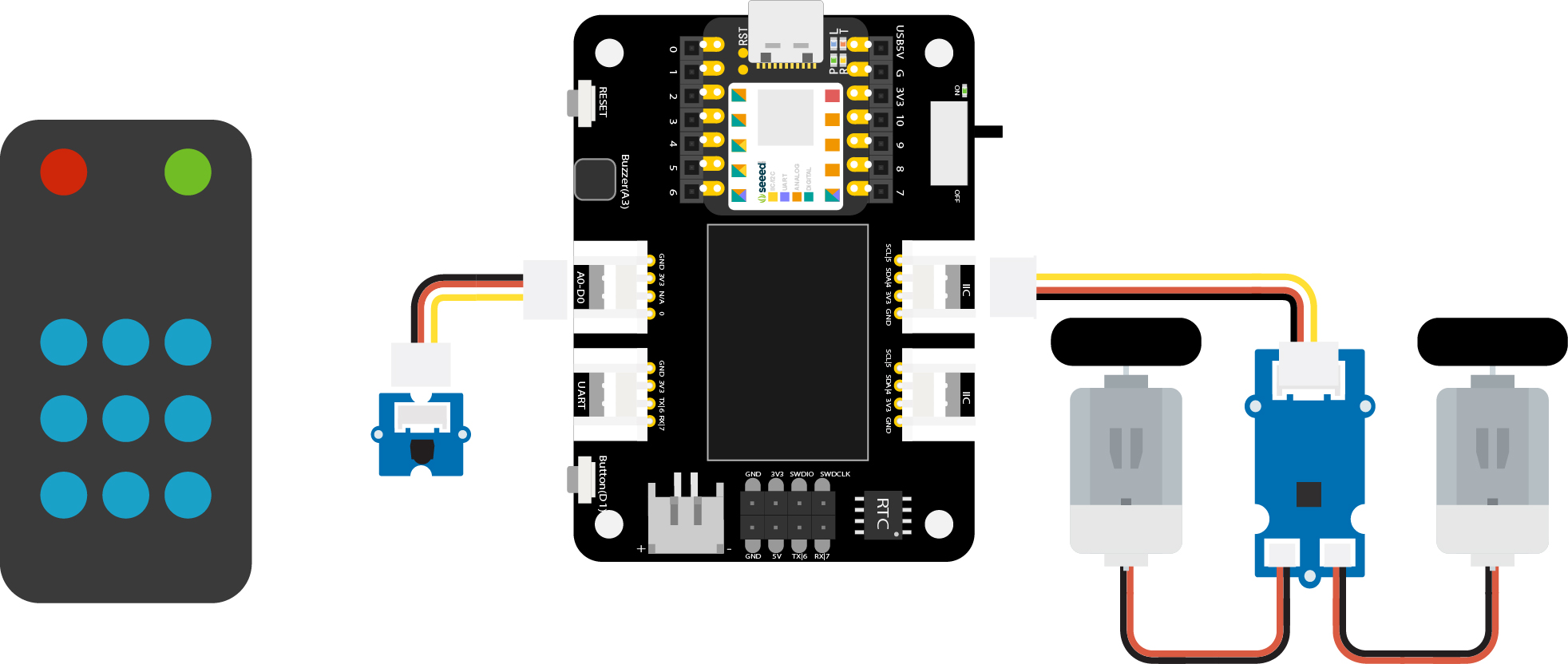
项目 2 - 遥控小车
概述
这篇 Wiki 介绍了如何制作一个遥控汽车。
功能
- 小型汽车,能够轻松穿过狭窄的道路
所需组件
硬件连接
请按照相同颜色的线连接每个传感器到扩展板上。请将红外传感器的 Grove 电缆连接到 D0,将 Mini Motor Driver 的 Grove 电缆连接到 I2C。
Arduino 指南
步骤 1. 按照连接图连接所有传感器到扩展板上。
步骤 2. 下载 Arduino IDE
步骤 3. 安装 Arduino-IRremote 和 Motor driver 库,以下是 如何安装库的指南。
步骤 4. 将代码复制到 Arduino IDE 中并上传。
代码
#include <Arduino.h>
#include <U8g2lib.h>
#include <IRremote.h>
#include <SparkFunMiniMoto.h>  // 引入 MiniMoto 库
// 创建两个 MiniMoto 实例,使用不同的地址设置。
MiniMoto motor0(0xC4); // A1 = 1, A0 = clear
MiniMoto motor1(0xC0); // A1 = 1, A0 = 1 (默认)

#define FAULTn  1     // 用于故障检测的引脚。

int RECV_PIN = 0; // 设置引脚 2 为红外控制
IRrecv irrecv(RECV_PIN);
decode_results results;

void setup() {
  Serial.begin(9600);
  Serial.println("启用 IRin");  // 提示启用红外
  irrecv.enableIRIn(); // 启动接收器
  pinMode(FAULTn, INPUT);
}

void loop() {
  if (irrecv.decode(&results)) { // 检查红外信号
    if (results.value == 2155862055) {
      // 前进  2155862055
      motor0.drive(-600);
      motor1.drive(600);
      delayUntil(20);
    }
    if (results.value == 2155813095) {
      // 刹车   2155813095
      motor0.brake();
      motor1.brake();
      delay(100);
    }
    if (results.value == 2155823295) {
      // 后退  2155823295
      motor0.drive(600);
      motor1.drive(-600);
      delayUntil(20);
    }
    if (results.value == 2155829415) {
      // 停止  2155829415
      motor0.stop();
      motor1.stop();
      delay(100);
    }
    if (results.value == 2155821255) {
      // 向右转   2155821255
      motor0.drive(600);
      motor1.drive(600);
      delayUntil(20);
    }
    if (results.value == 2155837575) {
      // 向左转    2155837575
      motor0.drive(-600);
      motor1.drive(-600);
      delayUntil(20);
    }
    irrecv.resume();                    // 接收下一条指令

  }
  delay(100);
}

void delayUntil(unsigned long elapsedTime) {
  unsigned long startTime = millis();
  while (startTime + elapsedTime > millis()) {
    if (digitalRead(FAULTn) == LOW) {
      byte result = motor0.getFault();
      result = motor1.getFault();
    }
  }
}
项目 3 - 指纹解锁宝箱 - Seeed Studio XIAO
概述
这个宝箱可以存放您的重要物品,不用担心有人会拿走您的东西。宝箱具有指纹功能来保护您的物品。如果指纹授权失败,蜂鸣器会报警,LED 环会显示红色。只有您的指纹在开始时已注册到板子上,之后将手指放到板子上,当指纹通过授权时,LED 环会显示绿色。
功能
- 轻松记录您的指纹
- LED 环可以提醒锁的状态
- OLED 屏幕可以显示当前信息
- 蜂鸣器可以提醒指纹是否通过授权
所需组件
硬件连接
请按照图片所示将每个模块连接到扩展板上。将指纹模块连接到 XIAO 扩展板的 UART 端口,将舵机连接到 XIAO 扩展板的 D0 端口。
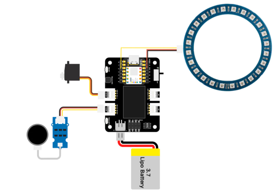
注意,NeoPixel 环通过三根不同颜色的线直接连接到 XIAO 开发板的引脚:将 NeoPixel 环的 DIN 引脚通过黄色线连接到 XIAO 的 D1 引脚,将 NeoPixel 环的 VIN 引脚通过红色线连接到 XIAO 的 3V3 引脚,将 NeoPixel 环的 GND 引脚通过黑色线连接到 XIAO 的 GND 引脚。

Arduino 指南
步骤 1. 按照连接图连接所有传感器到扩展板上。
步骤 2. 下载 Arduino IDE
步骤 3. 安装 u8g2、Servo、Seeed_Arduino_KCT202 和 Seeed_LED_Ring 库,以下是 如何安装库的指南。
步骤 4. 将代码复制到 Arduino IDE 中,然后上传。
演示
- 录入指纹
屏幕会在开始时显示“指纹录入”,您只需将手指放在指纹设备上,程序会分析您的指纹,完成注册。
- 身份认证(通过认证)
屏幕会显示“请验证”,您需要将手指放在指纹设备上,随后 LED 环会变为绿色。
- 身份认证(未通过认证)
如果其他人将手指放在设备上,LED 环会变为红色,板子会显示“身份拒绝”,同时警报会响起。
代码
#include <Servo.h>
#include <Arduino.h>
#include <U8x8lib.h>
#include "ATSerial.h"
#include "Protocol.h"
#include "KCT202.h"
#include "Adafruit_NeoPixel.h"

#define PIXEL_PIN    2    // 数字 IO 引脚连接到 NeoPixels。
#define PIXEL_COUNT 24
#define debug SerialUSB
#define uart  Serial1
FingerPrint_KCT202<Uart, Serial_> kct202;
Adafruit_NeoPixel strip = Adafruit_NeoPixel(PIXEL_COUNT, PIXEL_PIN, NEO_GRB + NEO_KHZ800);

Servo myservo;

Protocol_oprt oprt;
uint8_t err_code = 0;
uint8_t param[10];
uint32_t param_len;
int pos = 0;
const int buttonPin = 1;
int buttonState = 0;
int BuzzerPin = A3;

U8X8_SSD1306_128X64_NONAME_HW_I2C u8x8(/* reset=*/ U8X8_PIN_NONE);

void setup(void) {
  Serial.begin(115200);
  strip.setBrightness(255);
  strip.begin();
  strip.show(); // 初始化所有像素为“关闭”
  colorWipe(strip.Color(125, 0, 125), 50);
  u8x8.begin();
  u8x8.setFlipMode(0);
  debug.begin(115200);
  pinMode(buttonPin, INPUT_PULLUP);
  pinMode(BuzzerPin, OUTPUT);
  kct202.begin(uart, debug);
  myservo.attach(0);
  myservo.write(0);
  kct202.autoRegisterFingerPrint(1, 4, LED_OFF_AFTER_GET_GRAGH | PRETREATMENT_GRAGH | NOT_RET_FOR_EVERY_STEP | OVERRIDE_CURR_FINGER_PRINT);

  u8x8.setFont(u8x8_font_chroma48medium8_r);
  u8x8.setCursor(0, 3);
  u8x8.print("指纹录入");
  if (0 == kct202.getRegisterResponAndparse()) {
    debug.println("注册成功!");
    u8x8.setFont(u8x8_font_chroma48medium8_r);
    u8x8.setCursor(0, 3);
    u8x8.print("    准备中    ");
    delay(500);
    colorWipe(strip.Color(0, 125, 125), 50);
    u8x8.setCursor(0, 3);
    u8x8.print("   *** 3 ***    ");
    delay(500);
    u8x8.setCursor(0, 3);
    u8x8.print("   *** 2 ***    ");
    delay(500);
    u8x8.setCursor(0, 3);
    u8x8.print("   *** 1 ***    ");
    delay(500);
    u8x8.setCursor(0, 3);
    u8x8.print("   注册完成");
    delay(800);
  }
}

void loop(void) {
  uint16_t finger_num = 0;

  kct202.autoVerifyFingerPrint(CHECK_ALL_FINGER_TEMP,
                               LED_OFF_AFTER_GET_GRAGH | PRETREATMENT_GRAGH | NOT_RET_FOR_EVERY_STEP);
  u8x8.setFont(u8x8_font_chroma48medium8_r);
  u8x8.setCursor(0, 3);
  u8x8.print(" 请验证指纹  ");

  if (0 == kct202.getVerifyResponAndparse(finger_num)) {
    debug.println("验证成功!");
    debug.print("您的指纹 ID = ");
    debug.println(finger_num, HEX);
    colorWipe(strip.Color(0, 255, 30), 50);
    u8x8.setFont(u8x8_font_chroma48medium8_r);
    u8x8.setCursor(0, 3);
    u8x8.print("身份确认");
    delay(800);

    analogWrite(BuzzerPin, 128);
    delay(100);
    analogWrite(BuzzerPin, 0);
    delay(100);
    analogWrite(BuzzerPin, 128);
    delay(100);
    analogWrite(BuzzerPin, 0);
    delay(100);

    for (pos = 0; pos <= 90; pos += 1) {
      myservo.write(pos);
      delay(15);
    }
    while (1) {
      buttonState = digitalRead(buttonPin);
      u8x8.setFont(u8x8_font_chroma48medium8_r);
      u8x8.setCursor(0, 3);
      u8x8.print("请关闭锁    ");
      Serial.println(pos);
      Serial.println(buttonState);
      if (buttonState == LOW && pos == 91) {
        for (pos = 91; pos >= 0; pos -= 1) { // 从 180 度到 0 度
          u8x8.setFont(u8x8_font_chroma48medium8_r);
          u8x8.setCursor(0, 3);
          u8x8.print("锁正在关闭    ");
          myservo.write(pos);              // 告诉舵机移动到变量 'pos' 的位置
          delay(15);                       // 等待 15 毫秒让舵机到达位置
        }
        colorWipe(strip.Color(255, 0, 0), 50);
        break;
      }
    }
  }

  else {
    colorWipe(strip.Color(255, 0, 0), 50);
    u8x8.setFont(u8x8_font_chroma48medium8_r);
    u8x8.setCursor(0, 3);
    u8x8.print(" 身份拒绝 ");
    delay(200);

    analogWrite(BuzzerPin, 250);
    delay(2000);
    analogWrite(BuzzerPin, 0);
    delay(100);

    u8x8.setCursor(0, 3);
    u8x8.print("  请重试  ");
    delay(1500);
  }
}

void colorWipe(uint32_t c, uint8_t wait) {
  for (uint16_t i = 0; i < strip.numPixels(); i++) {
    strip.setPixelColor(i, c);
    strip.show();
    delay(70);
  }
}
项目 4 - Seeed Studio XIAO 扩展基座 - Mjolnir
概述
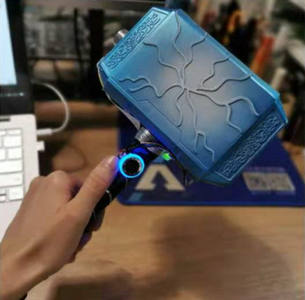
这个锤子模拟了雷神之锤 Mjolnir,您需要在设备上录入指纹,成为它的主人。锤子需要通过磁铁吸附在 Grove - 电磁铁上,直到主人通过指纹解锁后,锤子才能被拿走。
所需组件
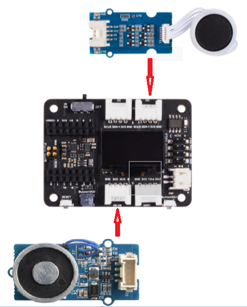
硬件连接
请使用 Grove 线连接扩展板和所需模块,将 Grove 电磁铁模块连接到 D0 端口,并将指纹模块连接到 I2C 端口。
Arduino 使用说明
步骤 1. 按照连接图连接所有传感器到扩展板。
步骤 2. 下载 Arduino IDE
步骤 3. 安装 u8g2 和 Seeed_Arduino_KCT202 库,参考此指南 如何安装库。
步骤 4. 将代码复制到 Arduino IDE 中并上传。
代码
#include <U8x8lib.h>
#include "ATSerial.h"
#include "Protocol.h"
#include "KCT202.h"

#define debug SerialUSB
#define uart  Serial1
FingerPrint_KCT202<Uart, Serial_> kct202;

Protocol_oprt oprt;
uint8_t err_code = 0;
uint8_t param[10];
uint32_t param_len;

int Electromagnet = 0;

U8X8_SSD1306_128X64_NONAME_HW_I2C u8x8(/* reset=*/ U8X8_PIN_NONE);

// setup 函数在按下复位按钮时运行一次:
void setup() {
  // 初始化数字引脚为输出。

  u8x8.begin();
  u8x8.setFlipMode(0);
  debug.begin(115200);
  pinMode(Electromagnet, OUTPUT);
  digitalWrite(Electromagnet, HIGH);  // 打开电磁铁(HIGH 是电压电平)
  kct202.begin(uart, debug);
  kct202.autoRegisterFingerPrint(1, 4, LED_OFF_AFTER_GET_GRAGH | PRETREATMENT_GRAGH | NOT_RET_FOR_EVERY_STEP | OVERRIDE_CURR_FINGER_PRINT);
  u8x8.setFont(u8x8_font_chroma48medium8_r);
  u8x8.setCursor(0, 3);
  u8x8.print("指纹录入");
  if (0 == kct202.getRegisterResponAndparse()) {
    u8x8.setFont(u8x8_font_chroma48medium8_r);
    u8x8.setCursor(0, 3);
    u8x8.print("    准备好    ");
    delay(500);
    u8x8.setCursor(0, 3);
    u8x8.print("   *** 3 ***    ");
    delay(500);
    u8x8.setCursor(0, 3);
    u8x8.print("   *** 2 ***    ");
    delay(500);
    u8x8.setCursor(0, 3);
    u8x8.print("   *** 1 ***    ");
    delay(500);
    u8x8.setCursor(0, 3);
    u8x8.print("   已注册");
    delay(800);
  }

}

// loop 函数会不断重复运行:
void loop() {

  uint16_t finger_num = 0;
  kct202.autoVerifyFingerPrint(CHECK_ALL_FINGER_TEMP, LED_OFF_AFTER_GET_GRAGH | PRETREATMENT_GRAGH | NOT_RET_FOR_EVERY_STEP);
  u8x8.setFont(u8x8_font_chroma48medium8_r);
  u8x8.setCursor(0, 3);
  u8x8.print(" 请验证指纹  ");

  if (0 == kct202.getVerifyResponAndparse(finger_num)) {
    u8x8.setFont(u8x8_font_chroma48medium8_r);
    u8x8.setCursor(0, 3);
    u8x8.print("身份确认成功");
    delay(800);
    digitalWrite(Electromagnet, LOW);  // 打开电磁铁(HIGH 是电压电平)
    delay(5000);
    digitalWrite(Electromagnet, HIGH);
  }

  else {
    u8x8.setFont(u8x8_font_chroma48medium8_r);
    u8x8.setCursor(0, 3);
    u8x8.print(" 身份验证失败 ");
    //    myservo.write(0);
    delay(200);

    u8x8.setCursor(0, 3);
    u8x8.print("  请重试  ");
    delay(1500);
    digitalWrite(Electromagnet, HIGH);  // 打开电磁铁(HIGH 是电压电平)

  }
}
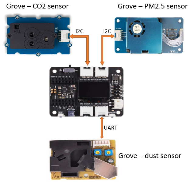
项目 5 - 空气质量传感器集线器 - Seeed Studio XIAO 扩展底座
概述
这是一个环境检测设备,通过 Grove - 激光 PM2.5 传感器、Grove - CO2 & 温湿度传感器以及 Grove - 粉尘传感器分别收集 PM2.5、PM10、温度、湿度、CO2 和粉尘颗粒数据。
所需组件
硬件连接
请按照图示连接每个传感器。将 CO2 传感器和 PM2.5 传感器分别连接到两个 I2C 端口,将粉尘传感器连接到 UART 端口。
Arduino 使用说明
步骤 1. 按照连接图连接所有传感器到扩展板。
步骤 2. 下载 Arduino IDE
步骤 3. 安装 u8g2、Seeed_PM2_5_sensor_HM3301 和 Seeed_SCD30 库,参考此指南 如何安装库。
步骤 4. 将代码复制到 Arduino IDE 中并上传。
代码
#include <Arduino.h>
#include <U8x8lib.h>
#include <Seeed_HM330X.h>
#include "SCD30.h"

#define SERIAL_OUTPUT SerialUSB
#define SERIAL SerialUSB

int pin = 7;
unsigned long duration;
unsigned long starttime;
unsigned long sampletime_ms = 5000;//采样时间 30s;
unsigned long lowpulseoccupancy = 0;
float ratio = 0;
float concentration = 0;

const int buttonPin = 1;
int buttonState = 0;
int memu = 0;

U8X8_SSD1306_128X64_NONAME_HW_I2C u8x8(/* reset=*/ U8X8_PIN_NONE);
HM330X sensor;
uint8_t buf[30];

const char* str[] = {"传感器编号: ", "PM1.0 浓度(CF=1,标准颗粒物,单位:ug/m3): ",
                     "PM2.5 浓度(CF=1,标准颗粒物,单位:ug/m3): ",
                     "PM10 浓度(CF=1,标准颗粒物,单位:ug/m3): ",
                     "PM1.0 浓度(大气环境,单位:ug/m3): ",
                     "PM2.5 浓度(大气环境,单位:ug/m3): ",
                     "PM10 浓度(大气环境,单位:ug/m3): ",
                    };


///////////////////////////////////////////////////////////////////
// PM2.5 浓度(大气环境,单位:ug/m3): 值
///////////////////////////////////////////////////////////////////
HM330XErrorCode print_result(const char* str, uint16_t value) {
  if (NULL == str) {
    return ERROR_PARAM;
  }
  //  SERIAL_OUTPUT.print(str);
  u8x8.setFont(u8x8_font_chroma48medium8_r);
  u8x8.setCursor(0, 0);
  u8x8.print("PM2.5: ");
  u8x8.setCursor(7, 0);
  u8x8.print(value);
  u8x8.setCursor(11, 0);
  u8x8.print("ug/m");
  Serial.println(value);
  return NO_ERROR;
}

HM330XErrorCode print_result_1(const char* str, uint16_t value) {
  if (NULL == str) {
    return ERROR_PARAM;
  }
  //  SERIAL_OUTPUT.print(str);
  u8x8.setFont(u8x8_font_chroma48medium8_r);
  u8x8.setCursor(0, 0);
  u8x8.print("PM10: ");
  u8x8.setCursor(7, 0);
  u8x8.print(value);
  u8x8.setCursor(11, 0);
  u8x8.print("ug/m");
  Serial.println(value);
  return NO_ERROR;
}

/*解析 buf 中的 29 个 uint8_t 数据*/
HM330XErrorCode parse_result(uint8_t* data) {
  uint16_t value = 0;
  if (NULL == data) {
    return ERROR_PARAM;
  }
  value = (uint16_t) data[6 * 2] << 8 | data[6 * 2 + 1];
  print_result(str[6 - 1], value);
  return NO_ERROR;
}


HM330XErrorCode parse_result2(uint8_t* data) {
  uint16_t value = 0;
  if (NULL == data) {
    return ERROR_PARAM;
  }
  value = (uint16_t) data[7 * 2] << 8 | data[7 * 2 + 1];
  print_result_1(str[7 - 1], value);
  return NO_ERROR;
}

////////////////////////////////////////////////////////////////////

/*30s*/
void setup() {
  Serial.begin(115200);
  Wire.begin();
  u8x8.begin();
  u8x8.setFlipMode(0);
  scd30.initialize();
  pinMode(pin, INPUT);
  pinMode(buttonPin, INPUT_PULLUP);
  starttime = millis();//获取当前时间;

}

void loop() {
  float result[3] = {0};
  duration = pulseIn(pin, LOW);
  lowpulseoccupancy = lowpulseoccupancy + duration;

  buttonState = digitalRead(buttonPin);

  if (buttonState == LOW) {
    memu++;
    delay(15);
    if (memu == 2) {
      memu = 0;
    }
  }
  Serial.println(memu);

  if (scd30.isAvailable() && memu == 0) {
    scd30.getCarbonDioxideConcentration(result);
    u8x8.setFont(u8x8_font_chroma48medium8_r);
    u8x8.setCursor(0, 3);
    u8x8.print("CO2: ");
    u8x8.setCursor(5, 3);
    u8x8.print(result[0]);
    u8x8.setCursor(12, 3);
    u8x8.print("ppm");
    delay(1000);
  }

  if (sensor.read_sensor_value(buf, 29) && memu == 0) {
    SERIAL_OUTPUT.println("HM330X 读取结果失败!!!");
  }
  if(memu == 0){
  parse_result(buf);
  }

  if ((millis() - starttime) > sampletime_ms  && memu == 0) {
    ratio = lowpulseoccupancy / (sampletime_ms * 10.0); // 整数百分比 0=>100
    concentration = 1.1 * pow(ratio, 3) - 3.8 * pow(ratio, 2) + 520 * ratio + 0.62; // 使用规格表曲线

    u8x8.setFont(u8x8_font_chroma48medium8_r);
    u8x8.setCursor(0, 6);
    u8x8.print("Dust: ");

    u8x8.setCursor(6, 6);
    u8x8.print(concentration);

    u8x8.setCursor(12, 6);
    u8x8.print("pcs");

    //    Serial.println(concentration);
    lowpulseoccupancy = 0;
    starttime = millis();
  }


  if (scd30.isAvailable() && memu == 1) {
    scd30.getCarbonDioxideConcentration(result);
    u8x8.setFont(u8x8_font_chroma48medium8_r);
    u8x8.setCursor(0, 3);
    u8x8.print("Temp: ");
    u8x8.setCursor(6, 3);
    u8x8.print(result[1]);
    u8x8.setCursor(10, 3);
    u8x8.print(" C   ");

    u8x8.setCursor(0, 6);
    u8x8.print("Humi: ");
    u8x8.setCursor(5, 6);
    u8x8.print(result[2]);
    u8x8.setCursor(8, 6);
    u8x8.print("  %     ");

    delay(1000);
  }

  if (sensor.read_sensor_value(buf, 29) && memu == 1) {
    SERIAL_OUTPUT.println("HM330X 读取结果失败!!!");
  }
  if(memu == 1){
  parse_result2(buf);
  }
}
项目 6 - Seeed Studio XIAO 扩展基板 - 心率监测
概述
这个简单且经济实惠的项目基于 Seeed Studio XIAO 扩展基板,用于报告心率。
所使用的设备具有 I2C 双线接口,因此可以将布线降到最低。
所需组件
硬件连接
如下图所示,将心率传感器连接到 XIAO 扩展板的 I2C 接口。
Arduino 使用说明
步骤 1. 按照连接图将所有传感器连接到扩展板上。
步骤 2. 下载 Arduino IDE
步骤 4. 将以下代码复制到 Arduino IDE 中并上传。
代码
#include <Arduino.h>
#include <U8x8lib.h>

#include <Wire.h>

// 初始化 OLED 显示屏
U8X8_SSD1306_128X64_NONAME_HW_I2C u8x8(/* reset=*/ U8X8_PIN_NONE);

void setup() {
  Serial.begin(9600); // 初始化串口通信
  Serial.println("心率传感器:");

  u8x8.begin(); // 初始化 OLED 显示屏
  u8x8.setFlipMode(1); // 设置显示屏翻转模式
  Wire.begin(); // 初始化 I2C 通信
}

void loop() {
  Wire.requestFrom(0xA0 >> 1, 1);    // 从从设备请求 1 字节数据
  while (Wire.available()) {         // 从设备可能发送少于请求的数据
    unsigned char c = Wire.read();   // 接收心率值(一个字节)
    u8x8.setFont(u8x8_font_chroma48medium8_r); // 设置字体

    // 显示心率值
    u8x8.setCursor(0, 3);
    u8x8.print("HeartRate: "); // 显示 "HeartRate: "
    u8x8.setCursor(10, 3);
    u8x8.print(c); // 显示心率值
    u8x8.setCursor(13, 3);
    u8x8.print("bpm"); // 显示 "bpm"
    Serial.println(c); // 在串口监视器中打印心率值
  }
  delay(500); // 延迟 500 毫秒
}
资源
- [PDF]ETA1038
- [PDF]ETA3410
- [PDF]ETA6003
- [PDF]PCF8563T
- [PDF]Seeed Studio Expansion Base for XIAO_v1.0_SCH_200824
- [SCH]Seeed Studio Expansion Base for XIAO_v1.0_200824
- [BRD]Seeed Studio Expansion Base for XIAO_v1.0_200824
常见问题解答
问题 1:XIAO 扩展板上的 PMIC 是否会在 5V 引脚上输出电源?
PMIC 不会输出电源;5V 是直接从 USB 获取的。5V 引脚上提供的电流等于 USB 连接可提供的电流。
技术支持与产品讨论
感谢您选择我们的产品!我们为您提供多种支持渠道,确保您在使用我们的产品时获得顺畅的体验。我们提供多种沟通方式,以满足不同的偏好和需求。