Grove Basic Kit for Raspberry Pi Pico

The Raspberry Pi Pico is a new popular low-cost, high-performance microcontroller board, so how to integrate Grove sensor to it? The grove shield perfectly solved this problem.
The Grove Shield for Pi Pico v1.0 is a plug-and-play shield for Raspberry Pi Pico which integrates with various kinds of Grove connectors, including 2I2C, 3Analog, 2UART, 3Digital ports, SWD debug interface and SPI pin, 3.3v/5v selectable power switch. It enables the build prototype and project in an easy and quick way without jumper wire and breadboard, you could explore infinite possibilities of Pico. The shield board is a stackable add-on board which acts as a bridge for Pi Pico and Seeed's Grove system.
Specification
| Parameter | Value/Range |
|---|---|
| Operating voltage | 3.3/5V |
| Operation Temperature | -25℃ to +85℃ |
| Analog Ports | 3 |
| Digital Ports | 3 |
| UART Ports | 2 |
| I2C Ports | 2 |
| Size | 56mm x56mm |
Compatible Boards
The Base Shield is tested and fully compatible with Pi Pico.
Hardware Overview

-
1-Analog Ports: include 3 anlog ports, A0, A1, A2.
-
2-Digital Ports: include 3 digital ports, D16, D18, D20.
-
3-UART Port: 2 UART port.
-
4-I2C Ports: 2 I2C ports.
-
5-Power Switch: 5V/3.3V selectable power switch.
-
6-SPI port: 1 spi0 port.
-
Dimension: 56mm * 56mm
Getting Started
Project 1: Different Sounds from a Buzzer
Materials Required
Step 1. Prepare the following items:
| Pi Pico | Grove Shield for Pi Pico | Grove - Buzzer | Grove - Rotary Angle Sensor |
|---|---|---|---|
 |  |  |  |
| Get ONE Now | Get ONE Now | Get ONE Now | Get ONE Now |
Step 2. Connect the Grove Buzzer to port A1 of the Grove Shield.
Step 3. Connect the Grove Rotary Angle Sensor to port A0 of the Grove Shield.
Step 4. Plug the Grove Shield into the Pi Pico.
Step 5. Connect the Pi Pico to your PC using a USB cable.

Software Setup
Step 1. Download Thonny IDE:
For Linux Development Environment:
You can install Thonny in different ways depending on your system:
-
Binary bundle for PC (Thonny + Python):
bash <(wget -O - https://thonny.org/installer-for-linux) -
Using pip:
pip3 install thonny -
For Debian, Raspbian, Ubuntu, Mint, and similar distributions:
sudo apt install thonny -
For Fedora:
sudo dnf install thonny
Step 2. Open Thonny and connect your computer to the Raspberry Pi Pico. In Thonny, go to the Run menu, select Select Interpreter, and choose "MicroPython (Raspberry Pi Pico)" from the dropdown. Then, select the COM port for your Pi Pico.
Note: If you don't see "MicroPython (Raspberry Pi Pico)" in the interpreter list, ensure you have the latest version of Thonny installed.


Step 3. If the Raspberry Pi Pico is connected and running MicroPython, Thonny should automatically connect to the REPL. Now, copy the following code into the Thonny IDE and press the green Run button.
from machine import Pin, PWM, ADC
from time import sleep

adc = ADC(0)  # ADC input (knob potentiometer) connected to A0
pwm = PWM(Pin(27))  # DAC output (buzzer) connected to A1
pwm.freq(10000)

while True:
    val = adc.read_u16()  # Read A0 port ADC value (65535~0)
    # Drive the buzzer, turn off the buzzer when the ADC value is less than 300
    if val > 300:
        pwm.freq(int(val / 10))
        pwm.duty_u16(10000)
    else:
        pwm.duty_u16(0)

    print(val)
    sleep(0.05)
Now, rotate the Grove Rotary Angle Sensor, and you will hear different sounds from the buzzer as you adjust the angle.
Project 2: Detecting Temperature and Humidity
- Option 1: DHT11 and SSD1315
- Option 2: DHT20 and LCD1602
Materials Required
Step 1. Prepare the following items:
| Pi Pico | Grove Shield for Pi Pico | Grove OLED Display 0.96" (SSD1315) | Grove Temperature & Humidity Sensor (DHT11) |
|---|---|---|---|
| |  |  |
Step 2. Connect the Grove OLED Display 0.96" to port I2C1 of the Grove Shield.
Step 3. Connect the Grove Temperature Humidity Sensor (DHT11) to port D18 of the Grove Shield.
Step 4. Plug the Grove Shield into the Pi Pico.
Step 5. Connect the Pi Pico to your PC using a USB cable.
Software Setup
Please refer to the software section of Demo 1.
- Copy the following code into Thonny IDE:
from ssd1306 import SSD1306_I2C
from dht11 import *
from machine import Pin, I2C
from time import sleep

i2c = I2C(1, scl=Pin(7), sda=Pin(6), freq=200000)  # OLED connected to I2C1
oled = SSD1306_I2C(128, 64, i2c)
dht2 = DHT(18)  # Temperature and humidity sensor connected to D18

while True:
    temp, humid = dht2.readTempHumid()  # Read temperature and humidity
    '''I2C port test and OLED display test'''
    oled.fill(0)  # Clear the screen
    oled.text("Temp:  " + str(temp), 0, 0)  # Display temperature on line 1
    oled.text("Humid: " + str(humid), 0, 8)  # Display humidity on line 2
    oled.show()
    sleep(0.5)
- Download the following required Python files to your local machine:
import time
from machine import Pin

MAXTIMINGS  = 85

DHT11 = 11
DHT22 = 22
DHT21 = 21
AM2301 = 21

class DHT(object):
    def __init__(self, data_pin,Type=DHT11):
        self.Data_pin = data_pin
        self.__pinData = Pin(data_pin, Pin.OUT)
        self.firstreading = True
        self.__pinData.value(1)
        self._lastreadtime = 0
        self.data=[0]*5
        self.temp = 0
        self.humid = 0

    def read(self):
        i=0
        j=0
        self.__pinData.value(1)
        #time.sleep(0.25)

        self.data[0] =  self.data[1] =  self.data[2] =  self.data[3] =  self.data[4] = 0

        # now pull it low for ~20 milliseconds
        pinData = Pin(self.Data_pin, Pin.OUT, None)
        pinData.value(0)
        time.sleep_ms(20)
        pinData.value(1)
        time.sleep_us(41)
        pinData = Pin(self.Data_pin, Pin.IN)
        DHT11_TIMEOUT = -1
        time_cnt=0
        while(0 ==pinData.value()):
            time.sleep_us(5)
            time_cnt = time_cnt+1
            if(time_cnt > 16):
                return

        # DHT11 pulls the bus up at least 80 US in preparation for sending sensor data.
        time_cnt=0
        while(1 == pinData.value()):
            time.sleep_us(5)
            time_cnt = time_cnt+1
            if(time_cnt > 16):
                return


        for j in range(5):
            i = 0
            result=0
            PINC = 1
            for i in range(8):

                while(not (PINC & pinData.value())):  # wait for 50us
                    pass
                    #print('wait 50us')
                time.sleep_us(25)

                if(PINC & pinData.value()):
                    result |=(1<<(7-i))
                while(PINC & pinData.value()):  # wait '1' finish
                    pass
                    #print('wait 1')
            self.data[j] = result

        pinData = Pin(self.Data_pin, Pin.OUT, None)
        pinData.value(1)

        dht11_check_sum = (self.data[0]+self.data[1]+self.data[2]+self.data[3]&0xff)
        # check check_sum
        if(self.data[4] is not dht11_check_sum):
            print("DHT11 checksum error")
        #print(self.data)
        if ((j >= 4) and ( self.data[4] == dht11_check_sum)):
            return True
        return False

    def readHumidity(self):
        if (self.read()):
            self.humid = float(self.data[0])
            self.humid = self.humid + float(self.data[1]/10)
        return self.humid

    def readTemperature(self):
        if (self.read()):
            self.temp = float(self.data[2])
            self.temp = self.temp + float(self.data[3]/10)
        return self.temp

    def readTempHumid(self):
        if (self.read()):
            self.temp = float(self.data[2])
            self.temp = self.temp + float(self.data[3]/10)
            self.humid = float(self.data[0])
            self.humid = self.humid + float(self.data[1]/10)
        return self.temp , self.humid
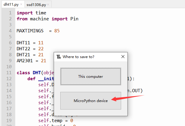
- Open dht11.py in Thonny IDE, click
File -> Save As -> MicroPython device, and save the file with the name dht11.py on your device.
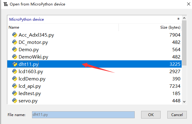
- Repeat the same process to save ssd1306.py to your MicroPython device.
Running the Project
Once both files are saved to your MicroPython device, run the demo code by pressing the green Run button in Thonny.
You should now see the temperature and humidity displayed on the OLED screen, similar to the image below:

Materials Required
Step 1. Prepare the following items:
| Pi Pico | Grove Shield for Pi Pico | Grove 16x2 LCD (White on Blue) | Grove Temperature & Humidity Sensor V2.0 (DHT20) |
|---|---|---|---|
| |  |  |
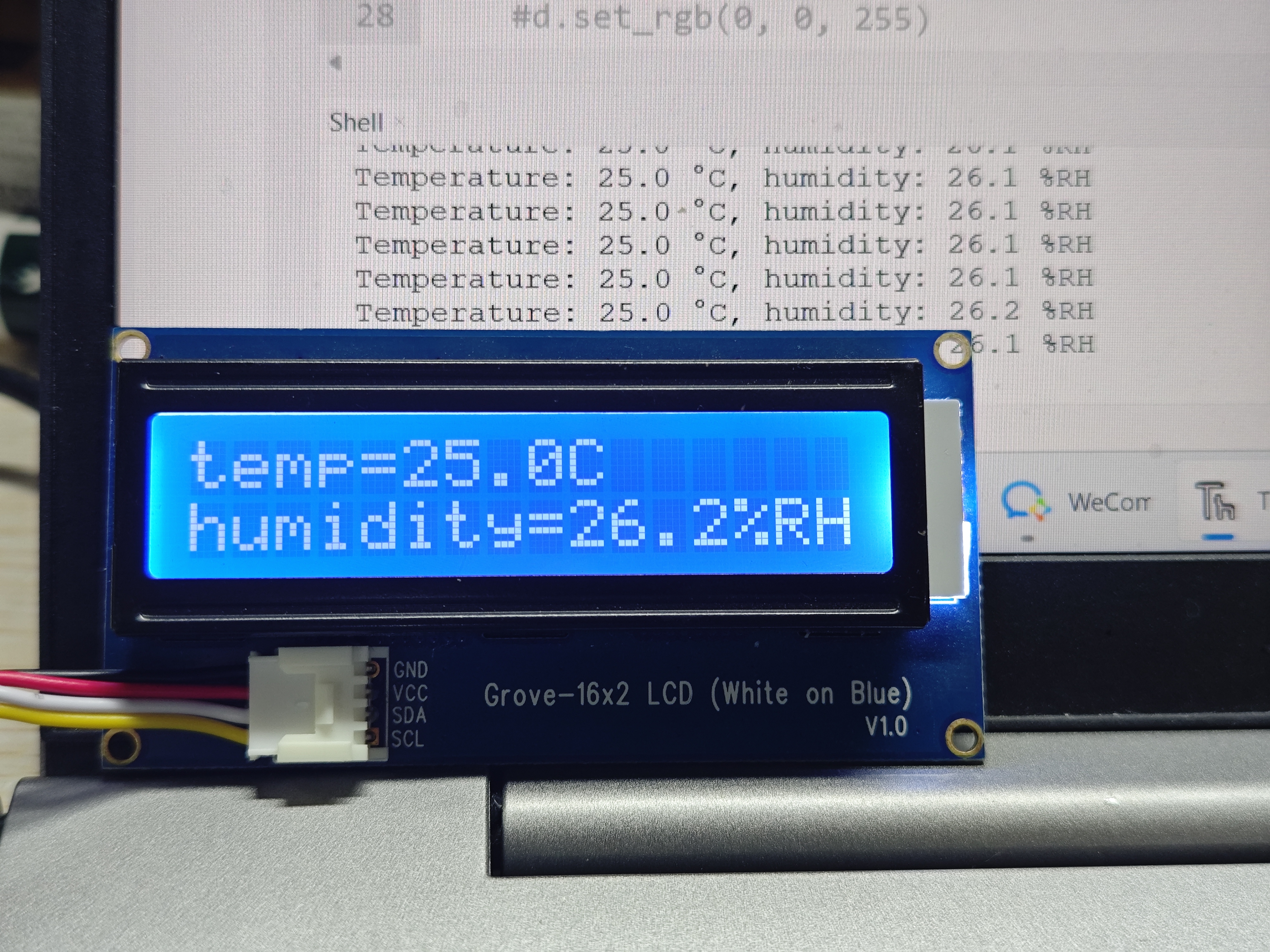
Step 2. Connect the Grove 16x2 LCD (White on Blue) to port I2C1 of the Grove Shield.
Step 3. Connect the Grove Temperature & Humidity Sensor V2.0 (DHT20) to port D18 of the Grove Shield.
Step 4. Plug the Grove Shield into the Pi Pico.
Step 5. Connect the Pi Pico to your PC using a USB cable.
Software Setup
Please refer to the software section of Demo 1.
- Copy the following code into Thonny IDE:
from lcd1602 import LCD1602
from dht20 import DHT20
from machine import I2C,Pin
from time import sleep

i2c1 = I2C(1,scl=Pin(7), sda=Pin(6), freq=400000)
d = LCD1602(i2c1, 2, 16)
i2c0 = I2C(0, scl=Pin(9), sda=Pin(8),freq=400000)
dht20 = DHT20(0x38, i2c0)

while True:

    measurements = dht20.measurements
    temp_rounded = round(measurements['t'], 1)
    humidity_rounded = round(measurements['rh'], 1)
    print(f"Temperature: {temp_rounded} °C, humidity: {humidity_rounded} %RH")
    d.home()
    d.print('temp=')
    d.print(str(temp_rounded))
    d.print('C')
    sleep(1)
    d.setCursor(0, 1)
    d.print('humidity=')
    d.print(str(humidity_rounded))
    d.print('%RH')
    sleep(1)
-
Download the following required Python files to your local machine:
-
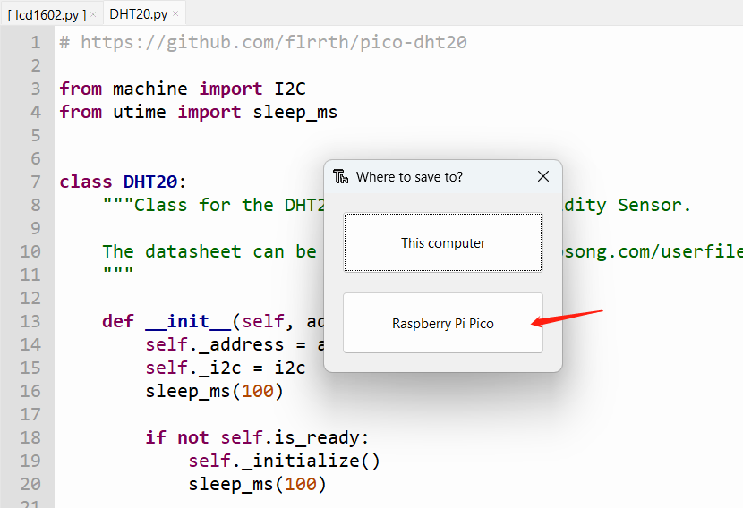
Open DHT20.py in Thonny IDE, click
File -> Save As -> MicroPython device, and save the file with the name DHT20.py on your device.
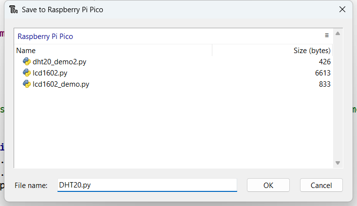
- Repeat the same process to save lcd1602.py to your MicroPython device.
Running the Project
Once both files are saved to your MicroPython device, run the demo code by pressing the green Run button in Thonny.
You should now see the temperature and humidity displayed on the OLED screen, similar to the image below:
Project 3: Controling Led and Relay
Materials Required
- Step 1. Prepare the below stuffs:
| Pi Pico | Grove Shield for Pi Pico | Grove-button | Grove-LED | Grove relay |
|---|---|---|---|---|
| |  |  |  |
| Get ONE Now | Get ONE Now | Get ONE Now | Get ONE Now | Get ONE Now |
- Step 2. Connect Grove button to digital pin 18 of Base Shield.
- Step 3. Connect Grove led to port D16 of Base Shield.
- Step 4. Connect Grove Relay to port D20 of Base Shield.
- Step 5. Plug Grove Shield for Pi Pico into Pi Pico.
- Step 6. Connect Pi Pico to PC through a USB cable.
Software
Please refer to the demo1 software part.
Copy below code to the Thonny IDE at first.
from machine import Pin

button = Pin(18, Pin.IN, Pin.PULL_UP)# button connect to D18
button.irq(lambda pin: InterruptsButton(),Pin.IRQ_FALLING)#Set key interrupt
led = Pin(16, Pin.OUT)#led connect to D16
relay = Pin(20, Pin.OUT)
tmp = 0
'''Key interrupt function, change the state of the light when the key is pressed'''
def InterruptsButton(): #button input
    global tmp
    tmp = ~tmp
    led.value(tmp)
    relay.value(tmp)
while True:
    pass
Now please click the green button to run the demo code.
Then you can press the grove button, you can control the led and relay open and close.

Project 4: Flashing Colors
Materials Required
- Step 1. Prepare the below stuffs:
| Pi Pico | Grove Shield for Pi Pico | RGB LED WS2813 mini |
|---|---|---|
| |  |
| Get ONE Now | Get ONE Now | Get ONE Now |
- Step 2. Connect RGB LED WS2813 mini to port 18 of Base Shield.
- Step 3. Plug Grove Shield for Pi Pico into Pi Pico.
- Step 4. Connect Pi Pico to PC through a USB cable.
Software
Please refer to the demo1 software part.
Copy below code to the Thonny IDE at first.
from ws2812 import WS2812
import time

BLACK = (0, 0, 0)
RED = (255, 0, 0)
YELLOW = (255, 150, 0)
GREEN = (0, 255, 0)
CYAN = (0, 255, 255)
BLUE = (0, 0, 255)
PURPLE = (180, 0, 255)
WHITE = (255, 255, 255)
COLORS = (BLACK, RED, YELLOW, GREEN, CYAN, BLUE, PURPLE, WHITE)

#WS2812(pin_num,led_count)
led = WS2812(18,30)

print("fills")
for color in COLORS:
    led.pixels_fill(color)
    led.pixels_show()
    time.sleep(0.2)

print("chases")
for color in COLORS:
    led.color_chase(color, 0.01)

print("rainbow")
led.rainbow_cycle(0)
Then please download the ws2812.py to your local. Use Thonny open ws2812.py, click file->save as->MicroPython device.
Input ws2812.py in File name column, click "ok", then the file is saved at File->Open->MicroPython device.

After you have save the files to your MicroPython device, now please click the green button to run the demo code. Then you can get the RGB LED WS2813 mini flash beautiful color as below.

Project 5: Detecting Sound and Light
Materials Required
- Step 1. Prepare the below stuffs:
| Pi Pico | Grove Shield for Pi Pico | grove sound sensor | Grove light sensor | Grove-16x2 LCD |
|---|---|---|---|---|
| |  |  |  |
| Get ONE Now | Get ONE Now | Get ONE Now | Get One Now | Get ONE Now |
- Step 2. Connect Grove sound sensor to analog pin 0 of Base Shield.
- Step 3. Connect Grove light to port A1 of Base Shield.
- Step 4. Connect Grove 16X2 lcd to port I2C1 of Base Shield.
- Step 5. Plug Grove Shield for Pi Pico into Pi Pico.
- Step 6. Connect Pi Pico to PC through a USB cable.
Software
Please refer to the demo1 software part.
Copy below code to the Thonny IDE at first.
#from lcd1602 import LCD1602_RGB  #LCD1602 RGB grove
from lcd1602 import LCD1602
from machine import I2C,Pin,ADC
from time import sleep
i2c = I2C(1,scl=Pin(7), sda=Pin(6), freq=400000)
d = LCD1602(i2c, 2, 16)
#d = LCD1602_RGB.display(i2c, 2, 16)
#d.set_rgb(255, 0, 0)
sleep(1)
light = ADC(0)
sound = ADC(1)

while True:

    lightVal = light.read_u16()
    soundVal = sound.read_u16()
    d.home()
    d.print('lightvalue=')
    d.print(str(lightVal))
    #d.set_rgb(0, 255, 0)
    sleep(1)
    d.setCursor(0, 1)
    d.print('soundvalue=')
    d.print(str(soundVal))
    #d.set_rgb(0, 0, 255)
    sleep(1)
Then please download the LCD1602.py to your local. Use Thonny open LCD1602.py, click file->save as->MicroPython device.
Input LCD1602.py in File name column, click "ok", then the file is saved at File->Open->MicroPython device.
In this example, the version of LCD1602 we are using is a monochrome backlit version, If you need to control the full-color backlit version of LCD1602, check out the functions in this library file to learn how to use it.

After you have save the files to your MicroPython device, now please click the green button to run the demo code. Then you can get the sound sensor and light sensor data as below.

Project 6: Detecting Motion
Materials Required
- Step 1. Prepare the below stuffs:
| Pi Pico | Grove Shield for Pi Pico | grove servo | Grove Mini Fan | Grove mini pir motion sensor |
|---|---|---|---|---|
| |  |  |  |
| Get ONE Now | Get ONE Now | Get ONE Now | Get ONE Now | Get ONE Now |
- Step 2. Connect Grove servo to analog pin 1 of Base Shield.
- Step 3. Connect Grove Mini fan to port D16 of Base Shield.
- Step 4. Connect Grove Mini pir motion sensor to port D18 of Base Shield.
- Step 5. Plug Grove Shield for Pi Pico into Pi Pico.
- Step 6. Connect Pi Pico to PC through a USB cable.
Software
Please refer to the demo1 software part.
Copy below code to the Thonny IDE at first.
from machine import Pin,ADC,PWM
from time import sleep
import utime

miniFun = Pin(16, Pin.OUT)
miniPir = Pin(18, Pin.IN)

pwm_Servo=PWM(Pin(27))
pwm_Servo.freq(500)
Servo_Val =0

while True:

    if  miniPir.value() == 1 :
        miniFun.value(1)

        while  Servo_Val<65535:
            Servo_Val=Servo_Val+50
            utime.sleep_ms(1)
            pwm_Servo.duty_u16(Servo_Val)
        while Servo_Val>0:
            Servo_Val=Servo_Val-50
            utime.sleep_ms(1)
            pwm_Servo.duty_u16(Servo_Val)

    else :
        miniFun.value(0)

        pwm_Servo.duty_u16(0)
Now please click the green button to run the demo code. Then you can get the grove mini fan and grove servo run When you hands swiping past the pir sensor as below.

Schematic Online Viewer
Resources
- [PDF] Pico python SDK
- [PDF] SCH
- [Eagle] PCB&SCH
Course Resources
- [ZIP] Beginners Guide of Raspberry Pi Pico Based on MicroPython
- [ZIP] Codes
- [ZIP] Libraries
Tech Support & Product Discussion
Thank you for choosing our products! We are here to provide you with different support to ensure that your experience with our products is as smooth as possible. We offer several communication channels to cater to different preferences and needs.