How to use rs485 and modbus with reComputer R1000
Introduction
This article mainly introduces how to use the 485 communication function of reComputer R1000, and tests the RS485 and Modbus communication functions. The work to use the RS485 function mainly lies in two points:
- Turn on power to the 485 transceiver. By default the r1000 does not have the power pin turned on, so turn it on when needed
- Controls the DE pin of the 485 transceiver, which is used by the device to switch between data sending mode and receiving mode. By default, R1000 does not control the DE pin, so when the user does not control this pin, the 485 can only communicate in one direction.
We wrote a C program to turn on the power and manage the DE pin, If your application is only responsible for receiving/sending data, you can use this program to ensure that the sending and receiving of the RS485 interface is normal.
Getting Start
Before you start this project, you may need to prepare your hardware and software in advance as described here.
Hardware Preparation
| reComputer R1000 |
|---|
 |
Software
- Using modbus poll on your W10 PC.You can also use other modbus testing tools
- Using modbusmechanic on reComputer R1000 and W10 PC.You can also use other modbus testing tools
- Using mobaxterm on your W10 PC.You can also use other serial port testing tools
- You need to download the minicom tool using the following command on the reComputer R1000:
sudo apt-get install minicom
Hardware Configuration
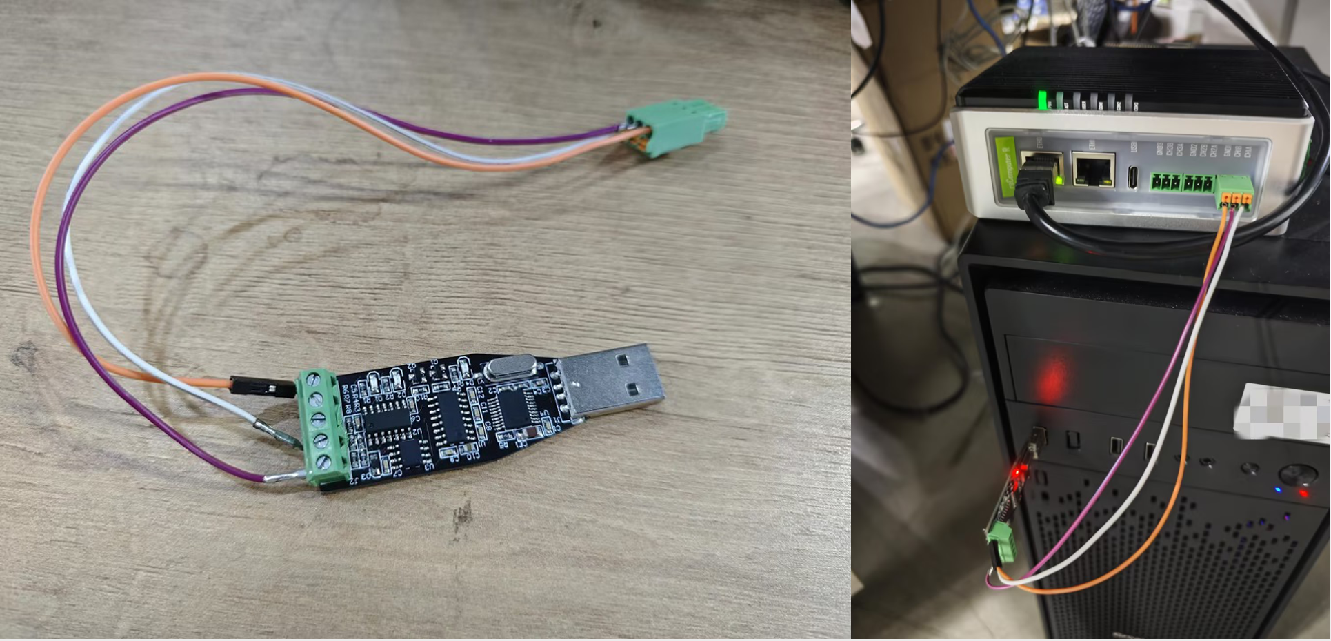
This test uses an RS485 to USB module to connect reComputer R1000 and W10 PC.
Steps to use the RS485 interface normally and perform Modbus testing
Step 1: First, you need to download the C program provided by us, and then refer to the contents of the ReadMe. Compile and run.
git clone https://github.com/Seeed-Studio/seeed-linux-dtoverlays
cd seeed-linux-dtoverlays/tools/rs485_control_DE/
sudo apt-get install libgpiod-dev
gcc -o rs485_DE rs485_DE.c -lgpiod
sudo ./rs485_DE /dev/ttyAMA2 /dev/gpiochip0 6 /dev/ttyAMA10 /dev/gpiochip2 12
This program will create a new ttyAMAx device, where the device number depends on the parameters you enter when running the program.
Step 2: After completing the first step, you can use the functions of RS485. Enter the following script on reComputer R1000 to open the minicom software
minicom -D /dev/ttyAMAx -b 9600
Among them, -D is followed by the device number you want to open, -b refers to the baud rate, and the device number needs to be the newly created device number in the first step.Then open MobaXterm on the W10 PC, create a new serial port terminal, select the serial port number, and the baud rate is 9600; finally, you can perform two-way communication with RS485. As shown in the figure, the content entered on the reComputer R1000 can be sent to via RS485. In W10 PC, the content entered on W10 PC can also be sent to reComputer R1000, and the two-way communication is normal.
Step 3: After testing the RS485 function, you can perform the Modbus function test. This step allows the reComputer R1000 to be tested as a Modbus slave.Open the ModbusMechanic software on reComputer R1000, select the device number and baud rate, then click on the simulated slave function in the upper left corner to add two coils; then open Modbus poll in W10 as the master station to read the coils of the slave station. Then open the display window of Modbus poll, and you can see that the sending and receiving messages of Modbus RTU are normal.
Step 4:This step allows the reComputer R1000 to be tested as a Modbus master. Open the ModbusMechanic software on both reComputer R1000 and W10 PC, and select the device number and baud rate. W10 PC refers to the third step of setting. Select Read Coils(0x01) on reComputer R1000 to read the coil of the slave, set Slave Node to 1, Register select the address you want to read, and finally click Transmit packet.
- The above example shows how to use one RS485 interface. If you want to use three 485 interfaces, you can use the following script to achieve it:
sudo ./rs485_DE /dev/ttyAMA2 /dev/gpiochip0 6 /dev/ttyAMA10 /dev/gpiochip2 12 &
sudo ./rs485_DE /dev/ttyAMA3 /dev/gpiochip0 17 /dev/ttyAMA11 &
sudo ./rs485_DE /dev/ttyAMA5 /dev/gpiochip0 24 /dev/ttyAMA12 &
ttyAMA10~ttyAMA12 corresponds to ttyAMA2~ttyAMA5 one-to-one. Use ttyAMA10~ttyAMA12 in your application for normal communication (ttyAMA2~ttyAMA5 cannot be used, you need to use the device number newly created by the script)
- If you just want to power on the RS485 transceiver, you can do it using the following script:
echo 590 > /sys/class/gpio/export
echo out > /sys/class/gpio/gpio590/direction
echo 1 > /sys/class/gpio/gpio590/value
At this time, the RS485 transceiver is turned on normally, but the DE pin is not controlled.If you want to use our c program to control the DE pin after executing these three commands, please restart or execute the following script:
echo 590 > /sys/class/gpio/unexport
This is because they use different file systems and there will be conflicts when accessing the same resource.
Tech Support & Product Discussion
Thank you for choosing our products! We are here to provide you with different support to ensure that your experience with our products is as smooth as possible. We offer several communication channels to cater to different preferences and needs.