reComputer R1000 Getting Started

The reComputer R1000 edge IoT controller is built on the high-performance Raspberry Pi CM4 platform, featuring a quad-core A72 processor with a maximum support of 8GB RAM and 32GB eMMC. Equipped with dual Ethernet interfaces that can be flexibly configured, it also includes 3 isolated RS485 channels supporting BACnet, Modbus RTU, Modbus TCP/IP protocols. With robust IoT network communication capabilities, the R1000 series supports multiple wireless communication options including 4G, LoRa®, Wi-Fi/BLE, allowing for flexible configurations to serve as corresponding wireless gateways. This controller is well-suited for remote device management, energy management, and various other scenarios in the field of smart buildings.
Available customization options: logo branding, packaging, and firmware flashing.
Feature
Designed for Building Automation System
-
Multiple isolated RS485 channels supports high and low speeds communication.
-
Supports BACnet, Modbus RTU, and Modbus TCP/IP protocol
-
Up to 8GB RAM supports the processing of thousands of data points, ensuring efficient performance
-
Clear dual-sided LED indicators help check operational status quickly
-
High-quality metal case, compatible with DIN-rail and Wall installation
-
Supports Yocto and Buildroot for customized OS
Powerful Performance
-
Powered by Raspberry Pi CM4
-
Broadcom BCM2711 quad-core Cortex-A72 (ARM v8) 64-bit SoC @ 1.5GHz
-
Up to 8GB RAM and 32GB eMMC
Rich Wireless Capabilities
-
On-chip Wi-Fi
-
On-chip BLE
-
Mini-PCIe1: LTE, USB LoRa®
-
Mini-PCIe2: SPI LoRa®, USB LoRa®
Rich Interfaces
-
3x RS485 (isolated)
-
1x 10M/100M/1000M Ethernet (Support PoE)
-
1x 10M/100M Ethernet
-
1x HDMI 2.0
-
2x Type-A USB2.0
-
1x Type-C USB2.0 (USB console for OS update)
-
1x SIM card slot
Safety and Reliability
-
Hardware Watchdog
-
UPS Supercapacitor(optional)
-
Metal casing with PC side panels
-
ESD: EN61000-4-2,level 3
-
EFT: EN61000-4-4, level 2
-
Surge: EN61000-4-5, level 2
-
Production Lifetime: reComputer R1000 will remain in production until at least December 2030
*4G and LoRa® modules does not come with reComputer R1000 by default, please purchase the relevant modules accordingly.
Naming Conventions

Specifications
| Parameter | Description | |
| Hardware Spec | ||
| Product Series | R10xx-10 | R10xx-00 |
| CPU | Raspberry Pi CM4, Quad-core Cortex-A72@ 1.5GHz | |
| Operating System | Raspberry Pi OS, Ubuntu | |
| RAM | 1GB/2GB/4GB/8GB | |
| eMMC | 8GB/16GB/32GB | |
| System Spec | ||
| Input | 2-pin Terminal Block | |
| PoE(as powered device) | IEEE 802.3af Standard 12.95W PoE* | |
| Supply Voltage(AC/DC) | 12~24V AC/9~36V DC | |
| Overvoltage Protection | 40V | |
| Power Consumption | Idle:2.88W; Full Load:5.52W | |
| Power Switch | No | |
| Reboot Switch | Yes | |
| Interface | ||
| Ethernet | 1 x 10/100/1000 Mbps(supports PoE*) | |
| 1 x 10/100 Mbps IEEE802.3/802.3u | ||
| USB | 2 x USB-A 2.0 Host | |
| 1 x USB-C 2.0 (For flashing OS) | ||
| RS485 | 3 x 3-pin Terminal Block (isolated) | |
| HDMI | 1 x HDMI 2.0 | |
| SIM Card Slot | supports Standard SIM Card | |
| M.2 Slot | supports M.2 NVMe SSD | |
| LED | 6 x LED indicators | |
| Buzzer | 1 | |
| Reset Button | 1 | |
| DSI(reserved) | supports LCD*(on board within the enclosure) | |
| Speaker(reserved) | supports Microphone*(on board within the enclosure) | |
| Wireless Communication | ||
| Wi-Fi 2.4/5.0 GHz | On-chip Wi-Fi* | No |
| BLE 5.0 | On-chip BLE* | No |
| LoRa® | USB LoRa®/SPI LoRa®* | |
| 4G Cellular | 4G LTE* | |
| Standards | ||
| EMC | ESD: EN61000-4-2, Level 3 | |
| EFT: EN61000-4-4, Level 2 | ||
| Surge: EN61000-4-5, Level 2 | ||
| Certification | CE, FCC | |
| TELEC | ||
| RoHS | ||
| REACH | ||
| Ambient Conditions | ||
| Ingress Protection | IP40 | |
| Operating Temperature | -30~70 °C | |
| Operating Humidity | 10~95% RH | |
| Storage Temperature | -40~80 °C | |
| Others | ||
| Supercapacitor UPS | SuperCAP UPS LTC3350 Module* | |
| Hardware Watchdog | 1~255s | |
| RTC | High Accuracy RTC | |
| Security | Encryption Chip TPM 2.0* | |
| ATECC608A | ||
| Heat Dissipation | Fanless | |
| Warranty | 2 years | |
| Production Lifetime | Until December 2030 | |
| Statement | Options marked with * require additional purchase according to the accessories list. | |
| Component and Interface Status Statement | ||
| Reserved | Designated for future use or expansion. | |
| Optional | Non-essential components, users can choose to include or exclude. | |
| Occupied | Currently in use and integral to product functionality. | |
| Included | Essential components provided with standard package. | |
| Mechanical | ||
| Dimension(W x H x D) | 130 mm x 93 mm x 49.6 mm | |
| Enclosure | 6061 Aluminum Alloy Casing with Transparent PC Side Panels | |
| Mounting | DIN-rail/Wall | |
| Weight(Net) | 560g | |
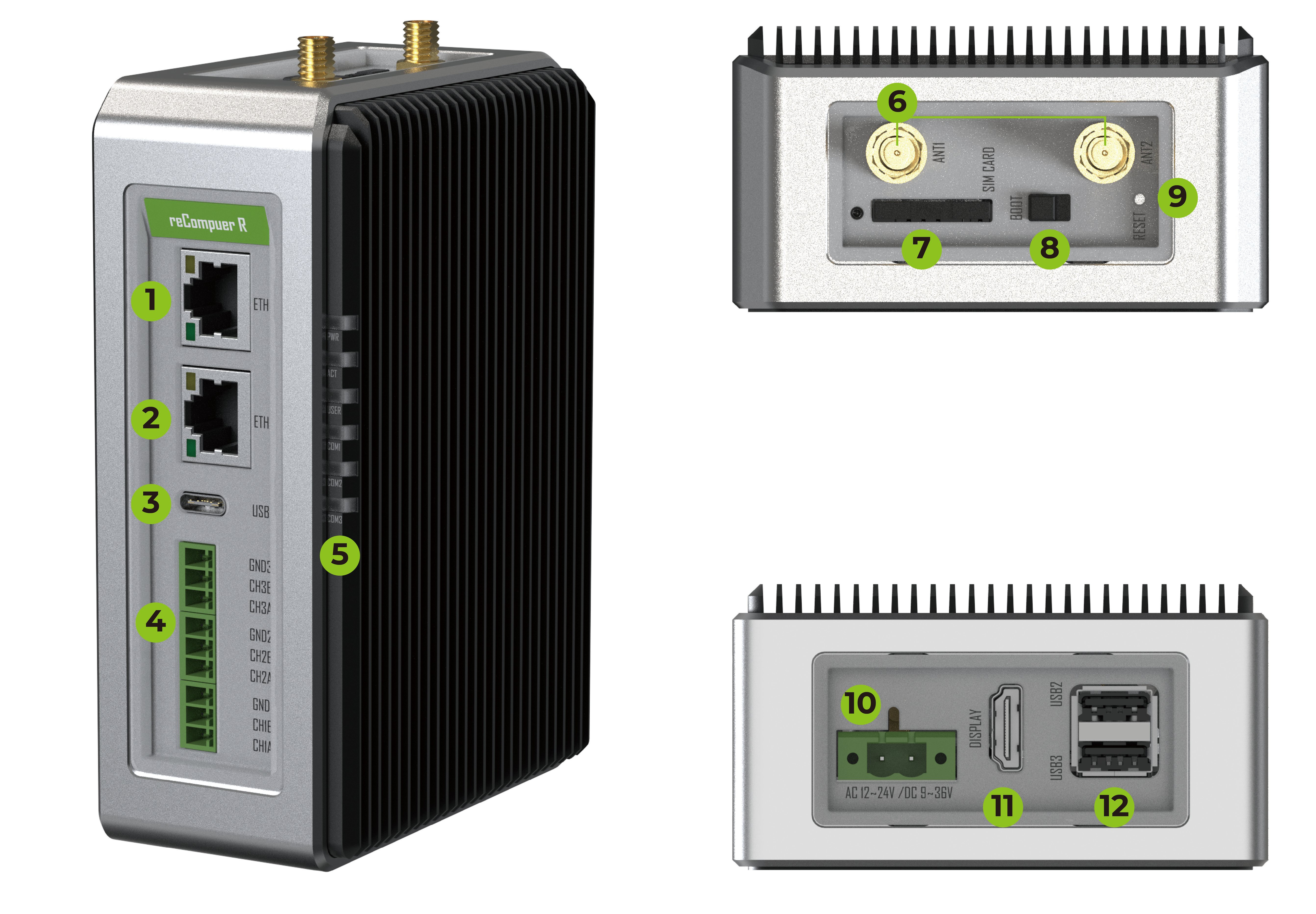
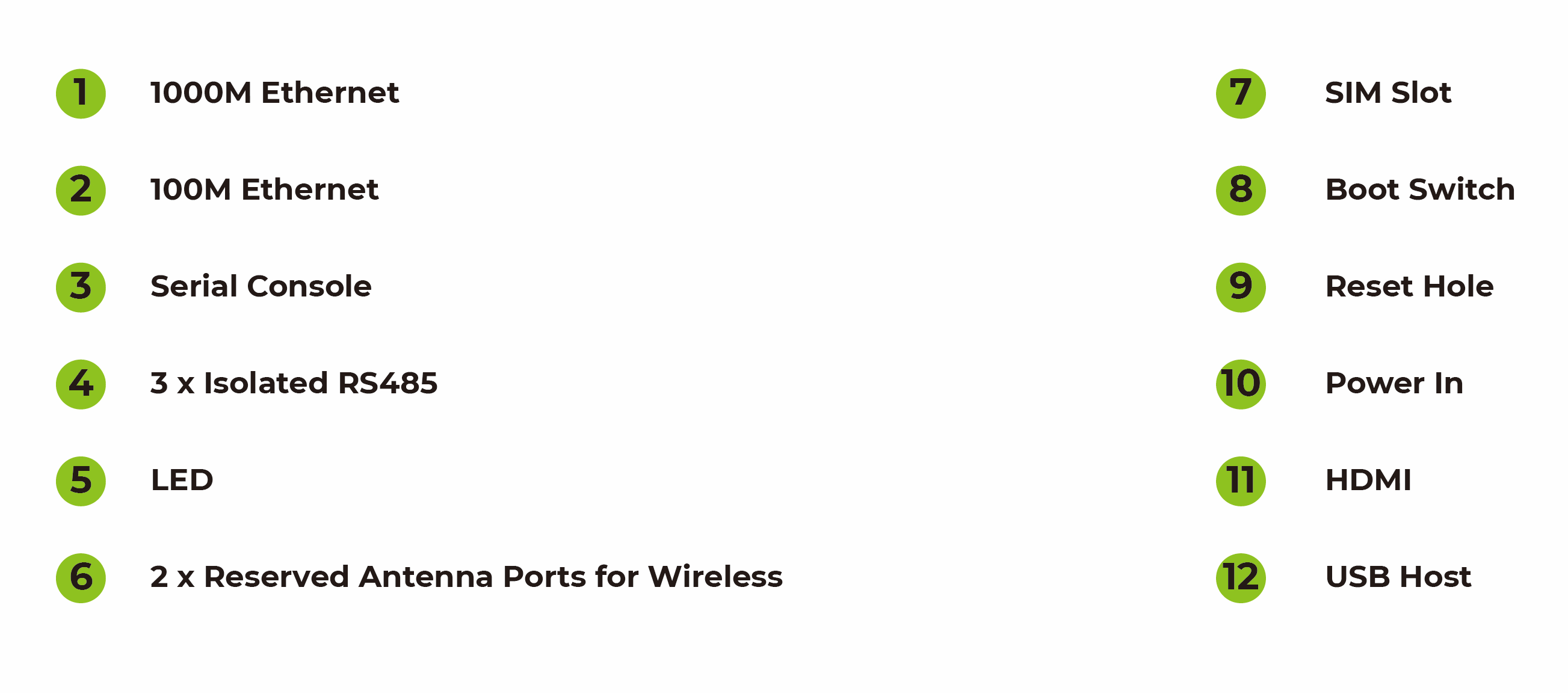
Hardware Overview
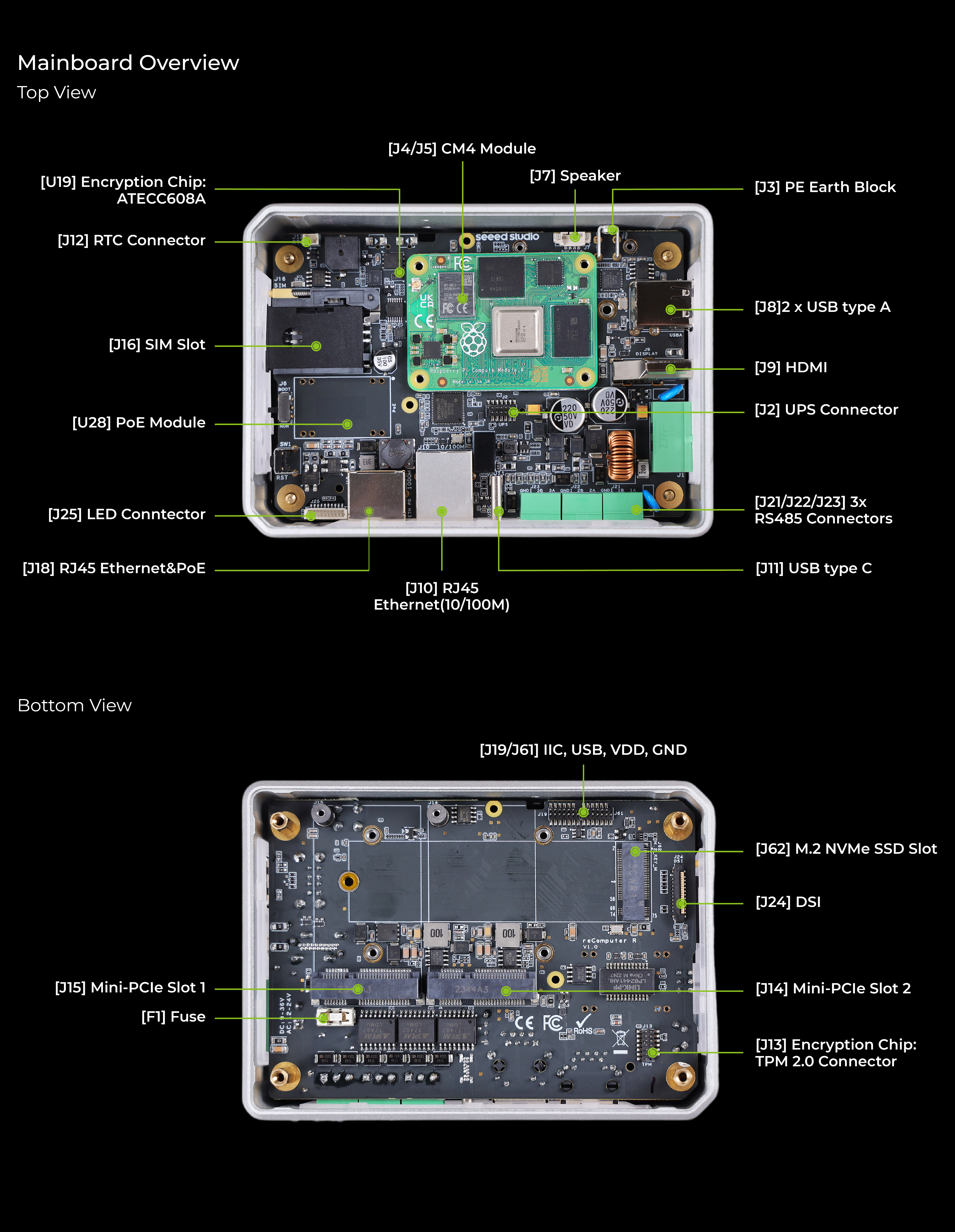
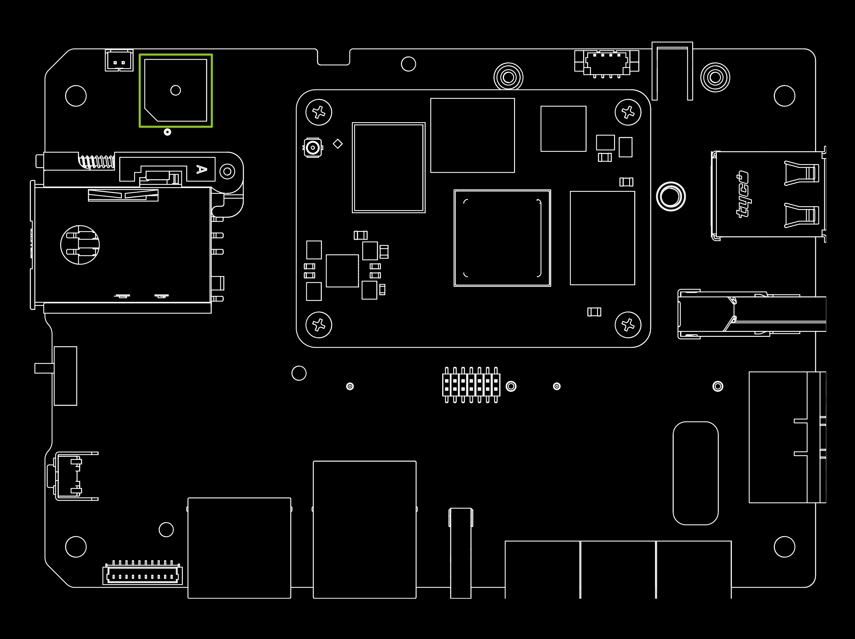
Mainboard Overview
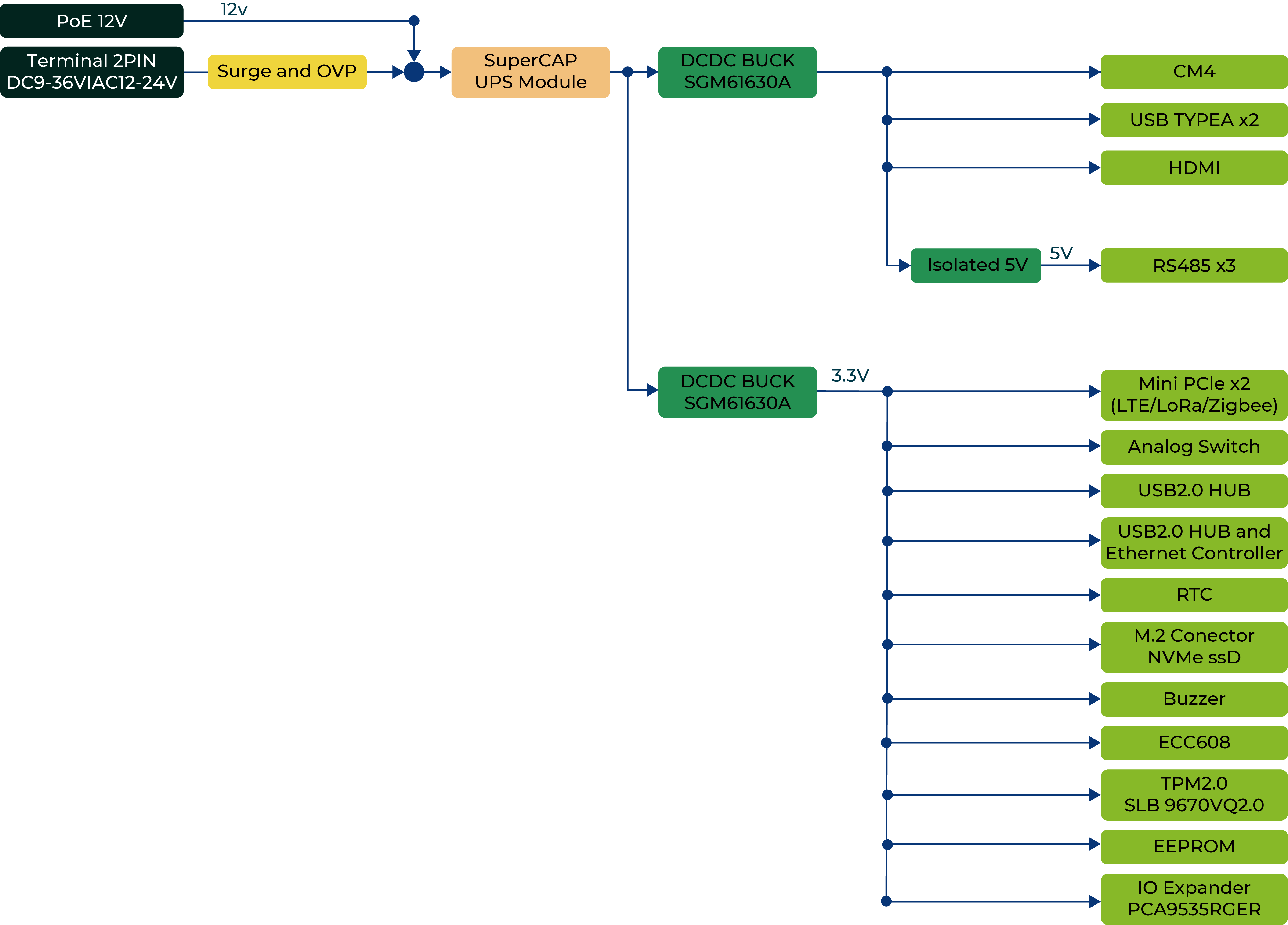
Power Diagram
The reComputer R1000 supports three power supply options: AC, DC terminal and PoE port. By default, the reComputer R1000 is powered through the AC/DC terminal (Official regional power adapter SKU:110061505/110061506), while the PoE power supply(PoE module, SKU:110991925) is optional. This provides flexibility in power supply selection and allows for easy integration with various power sources.
2-Pin Power terminal

The reComputer R1000 is supplied with a nominal AC voltage of 12~24 V or DC voltage of \9~36 V. The power supply is connected via the 2-pin power terminal block connector. To ground the reComputer R1000, the ground wire can be secured to the screw located at the top left corner of the power terminal.
The power solution utilizes a bridge rectifier diode for reverse polarity protection and is compatible with both AC and DC inputs. This ensures that regardless of how the power supply's positive and negative terminals are connected, the circuit will not be damaged. By using a bridge rectifier, the output voltage polarity remains fixed irrespective of the input DC polarity, providing effective reverse polarity protection.
POE (optional)
With the PoE module installed, the ETH0 port of reComputer R1000 can support PoE power supply, providing a convenient and efficientway to power the device over Ethernet. This option simplifies the installation process and reduces the amount of cabling required, making it an ideal solution for applications with limited power sources or where power outlets are not readily available.
- PoE input: Range 44~57V; Typical 48V
- PoE output: 12V, 1.1A Max.
It's worth noting that the PoE module provided with the reComputer R1000 is compliant with the IEEE 802.3af standard and can provide a maximum power supply of 12.95W. Therefore, if there is a need to connect high-power peripherals such as SSD or 4G modules, the PoE power supply may not be sufficient. In this case, it's recommended to use the AC/DC terminal for power supply instead to ensure stable and reliable operation of the device.
Power Consumption
Please refer to the table below for the tested power consumption of reComputer R1000 in Seeed Studio's laboratory. Please note that this value is for reference only, as the test methods and environment can result in variations in the results.
| Status | Voltage | Current | Power Consumption | Description |
|---|---|---|---|---|
| Shutdown | 24V | 51mA | 1.224W | Static power consumption test in shutdown and power-off state. |
| Idle | 24V | 120mA | 2.88W | To test the input current when supplying 24V power to the reComputer R1000 device without running any test programs. |
| Full Load | 24V | 230mA | 5.52W | Configure CPU to run at full load using the "stress -c 4" command. No external devices connected. |
Power On and Power Off
The reComputer R1000 does not come with a power button by default, and the system will automatically start up once power is connect- ed. When shutting down, please select the shutdown option in the operating system and wait for the system to fully shut down before cutting off power. To restart the system, simply reconnect to the power.
Please note that after shutting down, please wait for at least 10 seconds before restarting the system to allow for the internal capacitors to fully discharge.
Block Diagram
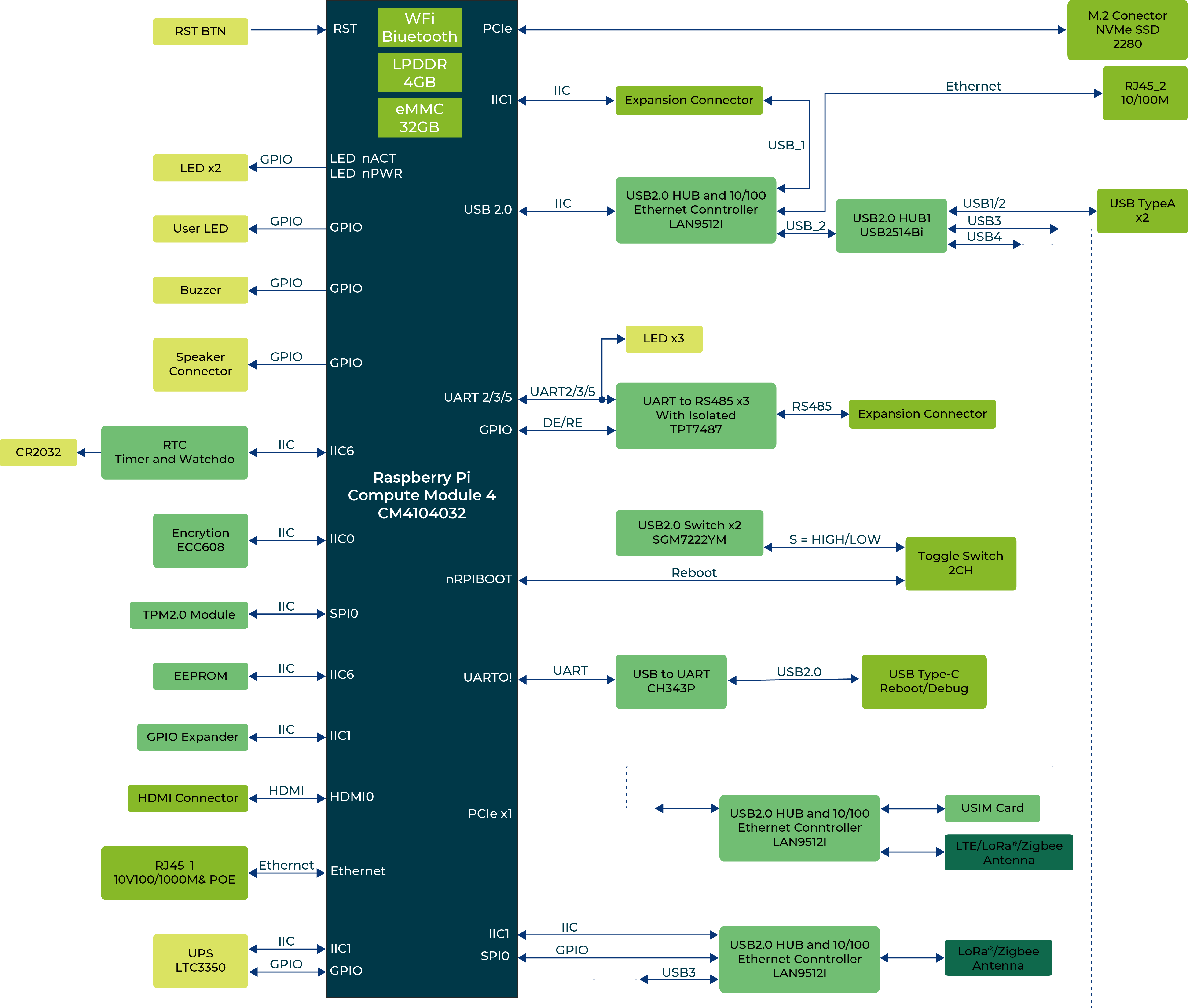
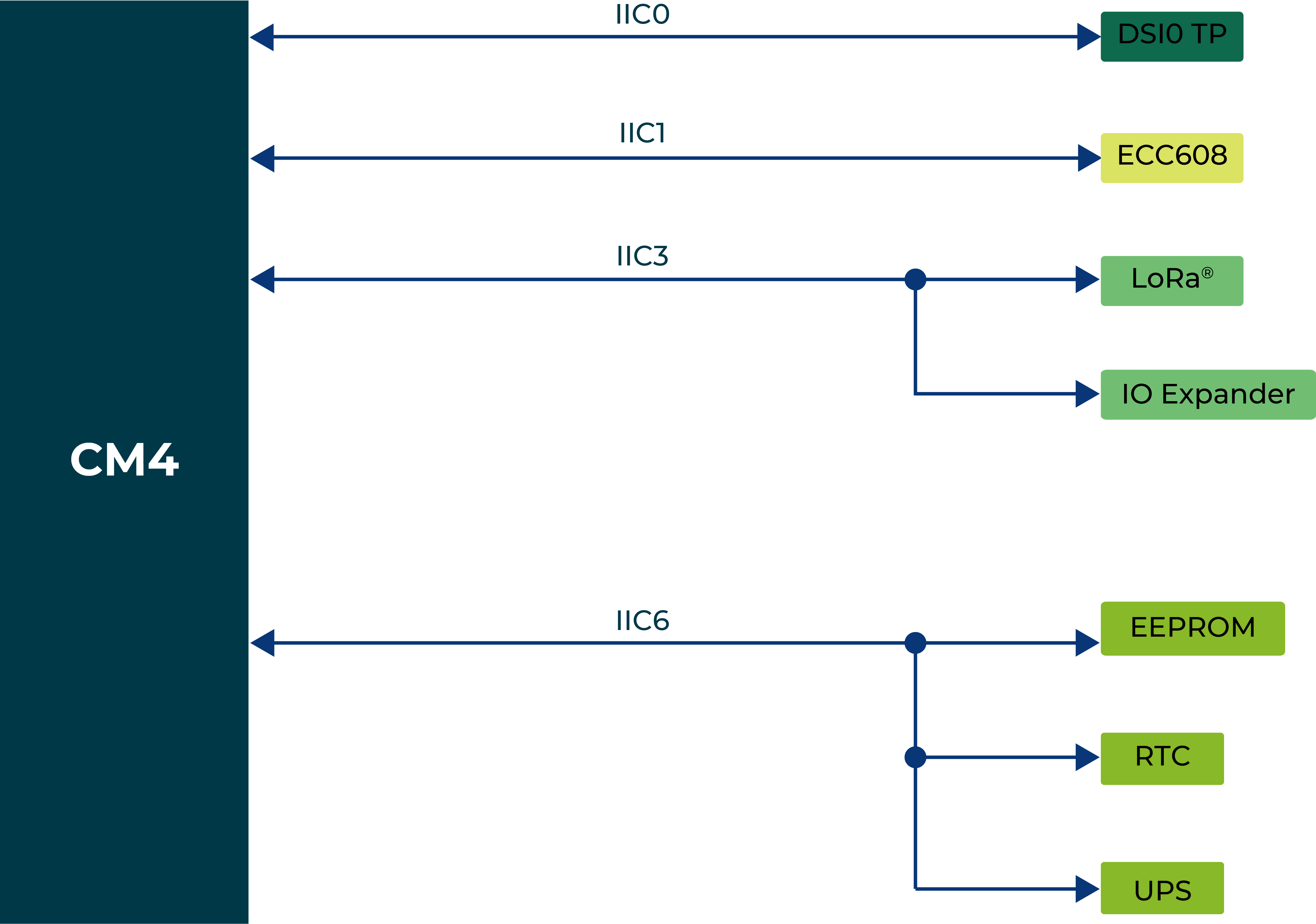
IIC Diagram
Interface
| Interface | ||
| Ethernet | 1 x 10/100/1000 Mbps IEEE 1588-2008(supports PoE*) | |
| 1 x 10/100 Mbps IEEE802.3/802.3u | ||
| USB | 2 x USB-A 2.0 Host | |
| 1 x USB-C 2.0 (for flashing OS) | ||
| RS485 | 3 x 3-pin Terminal Block (isolated) | |
| HDMI | 1 x HDMI 2.0 | |
| SIM Card Slot | supports Standard SIM Card | |
| M.2 Slot | supports M.2 NVMe SSD | |
| LED | 6 x LED indicators | |
| Buzzer | 1 | |
| Reset Button | 1 | |
| HDMI | 1 x HDMI 2.0 | |
| DSI | supports LCD*(on board within the enclosure) | |
| Speaker* | supports Microphone*(on board within the enclosure) | |
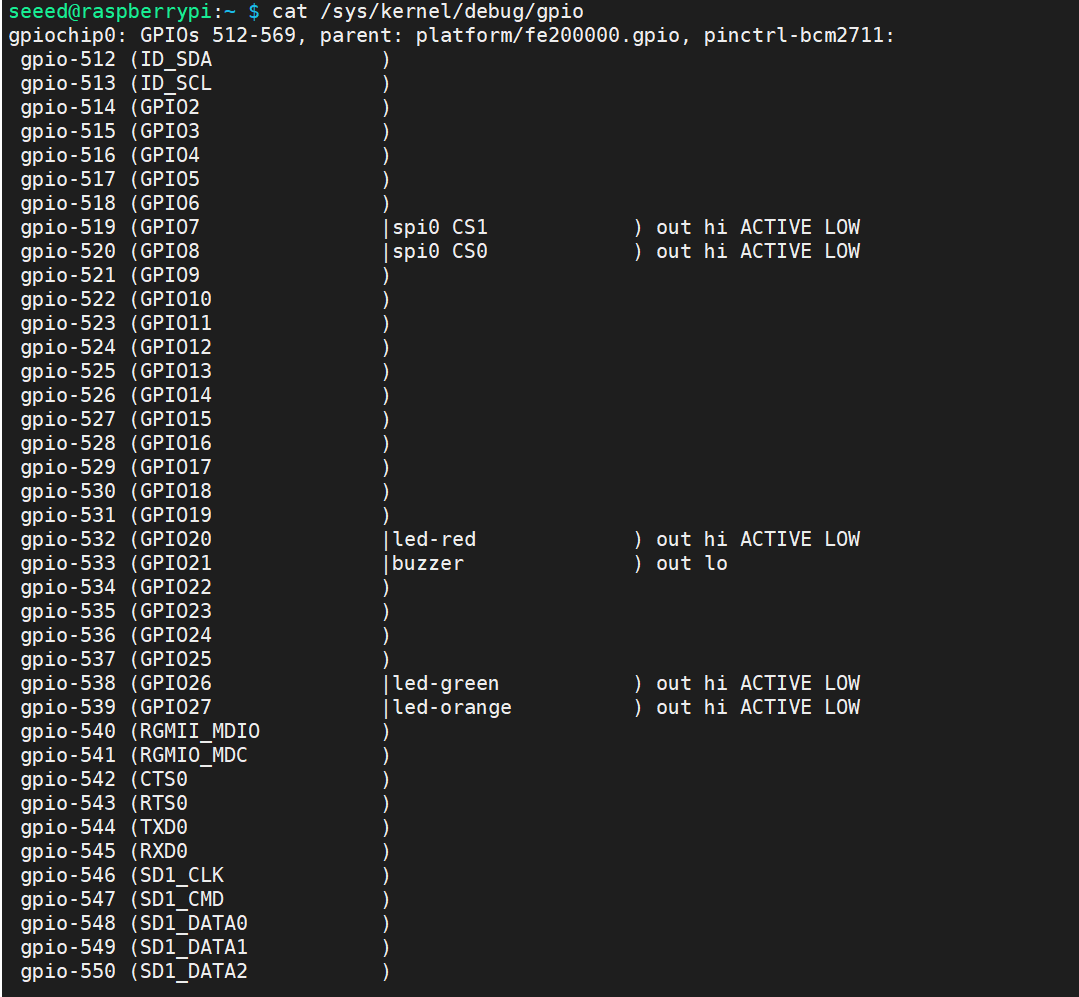
To query GPIO mappings and offsets, please use following command:
cat /sys/kernel/debug/gpio
LED Indicator Status
The reComputer R1000 features 6 LED indicators that serve to signal the machine's operational status. Please refer to the table below for the specific functions and status of each LED:
| LED Indicator | Color | Status | Description |
|---|---|---|---|
| PWR | Green | On | The device has been connected to power. |
| Off | The device is not connnected to power. | ||
| ACT | Green | Under Linux this pin will flash to signify eMMC access. If any error occurs during booting, then this LED will flash an error pattern which can be decoded using the look up table on the Raspberry Pi website. | |
| USER | Green/Red/Blue | Need to be defined by user. | |
| RS485-1 | Green | Off | No data transfer on RS485 channel 1. |
| Blink | RS485 channel 1 is receiveing or sending data. | ||
| RS485-2 | Green | Off | No data transfer on RS485 channel 2. |
| Blink | RS485 channel 2 is receiveing or sending data. | ||
| RS485-3 | Green | Off | No data transfer on RS485 channel 3. |
| Blink | RS485 channel 3 is receiveing or sending data. |
ACT Status table
| Long flashes | Short flashes | Status |
|---|---|---|
| 0 | 3 | Generic failure to boot |
| 0 | 4 | start*.elf not found |
| 0 | 7 | Kernel image not found |
| 0 | 8 | SDRAM failure |
| 0 | 9 | Insufficient SDRAM |
| 0 | 10 | In HALT state |
| 2 | 1 | Partition not FAT |
| 2 | 2 | Failed to read from partition |
| 2 | 3 | Extended partition not FAT |
| 2 | 4 | File signature/hash mismatch - Pi 4 |
| 4 | 4 | Unsupported board type |
| 4 | 5 | Fatal firmware error |
| 4 | 6 | Power failure type A |
| 4 | 7 | Power failure type B |
If the ACT LED blinks in a regular four blink pattern, it cannot find bootcode (start.elf) If the ACT LED blinks in an irregular pattern then booting has started. If the ACT LED doesn't blink, then the EEPROM code might be corrupted, try again without anything connected to make sure. For more detail please check the Raspberry Pi forum: STICKY: Is your Pi not booting? (The Boot Problems Sticky) - Raspberry Pi Forums For more detail please check the Raspberry Pi forum.
To control the user LEDs, we recommend using sysfs, a pseudo-filesystem provided by the Linux kernel that exposes information about various kernel subsystems, hardware devices, and their associated drivers. On the ReComputer R1000, we have abstracted the user LED interface into three device files (led-red, led-blue, and led-green), enabling users to control the LED lights simply by interacting with these files. The examples are as follows:
- To turn on the red LED, please enter following command in the Terminal:
echo 1 | sudo tee /sys/class/leds/led-red/brightness
- To turn off the red LED, please enter following command in the Terminal:
echo 0 | sudo tee /sys/class/leds/led-red/brightness
- You can turn on red and green LED at the same time, please enter following command in the Terminal:
echo 1 | sudo tee /sys/class/leds/led-red/brightness
echo 1 | sudo tee /sys/class/leds/led-green/brightness
Buzzer
The reComputer R1000 features an active buzzer, which can be used for various purposes such as alarm and event notifications. The buzzer is controlled through GPIO21 to CM4 in reComputer R1000 v1.0, and GPIO20 to CM4 in reComputer R1000 1.1.
To distinguish between the hardware revision (v1.0 and v1.1), you can refer to reComputer R1000 V1.1 Product change details.
For reComputer R1000 v1.0 users, the buzzer is connected to GPIO-21, to turn on/off the buzzer, Please enter following command in the Terminal:
raspi-gpio set 21 op dh # turn on
raspi-gpio set 21 op dl # turn off
For reComputer R1000 v1.1 users, the buzzer is connected to PCA9535 P15, to turn off(on) the buzzer, Please enter following command in the Terminal :
echo 591 | sudo tee /sys/class/gpio/export
echo out | sudo tee /sys/class/gpio/gpio591/direction
echo 1 | sudo tee /sys/class/gpio/gpio591/value # turn on
echo 0 | sudo tee /sys/class/gpio/gpio591/value # turn off
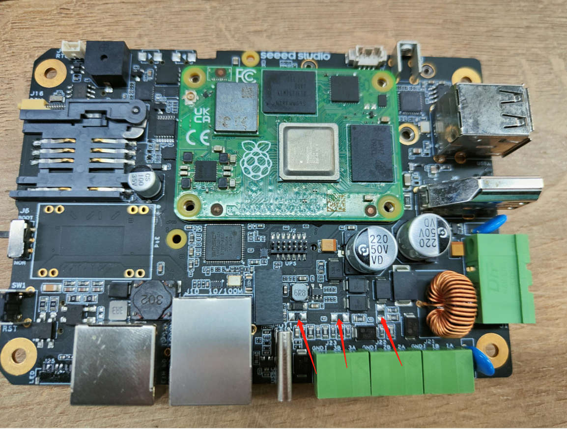
RS485
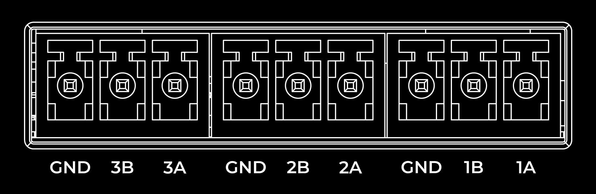
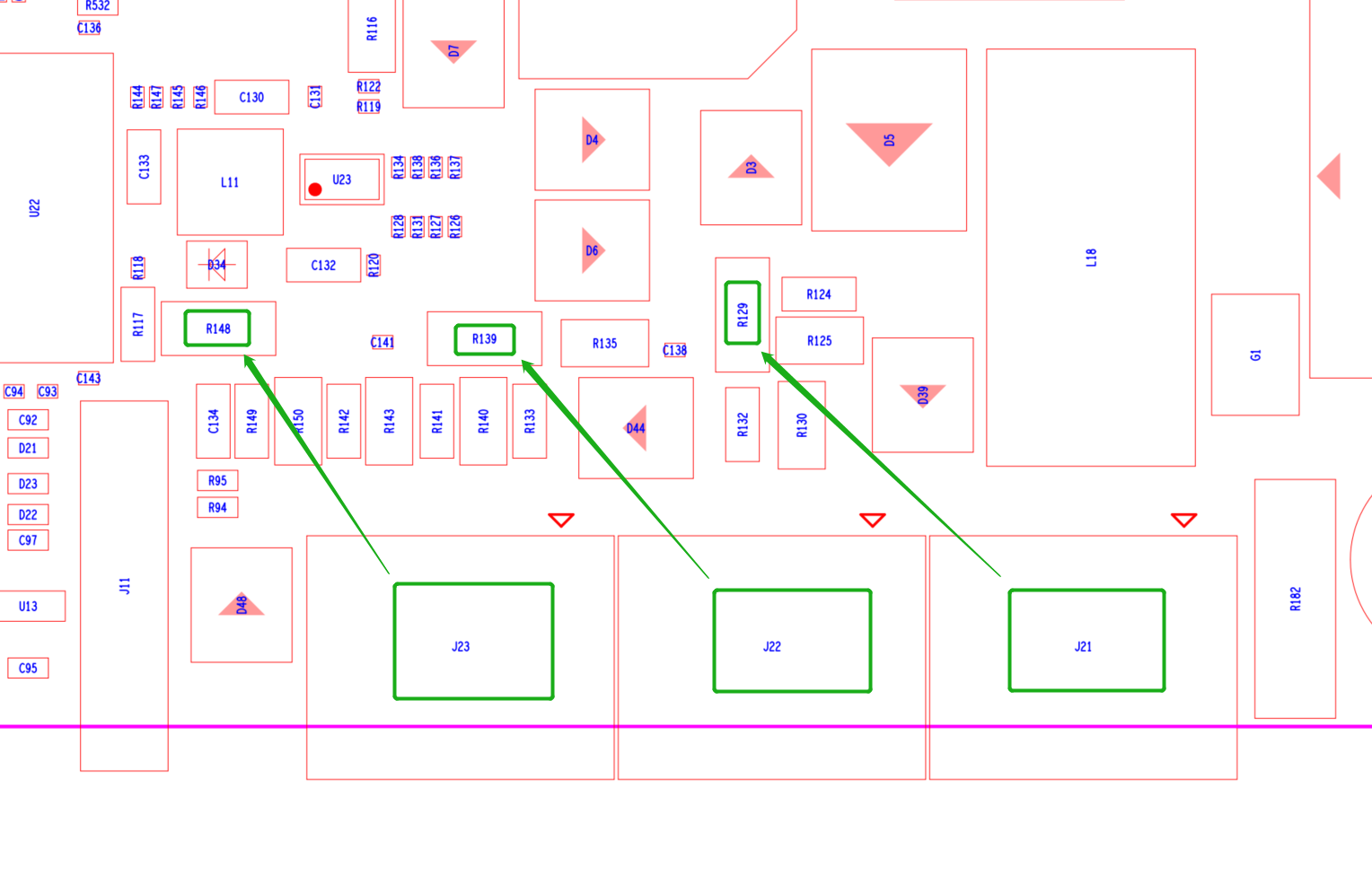
The reComputer R1000 is equipped with 3 sets of RS485 interface using 3-pin connector, which is isolated for both signal and power to ensure safe and reliable operation in industrial and automation applications. The RS485A and RS485B signals are isolated using capacitive isolation, which provides excellent EMI immunity and meets the high-speed communication requirements of the RS485 interface. By default, 120Ω terminal resistors is not installed. However, the packaging box includes five surface-mount resistors. If needed, users should solder the resistor onto the device themselves.
The RS485 interface uses an isolated power supply, which means that the ground signal for external devices connected to the RS485 interface should be connected to the GND_ISO pin.
These are the pins related to the 485 interface of reComputer for the data table.
| RS485 | RS485_POWER_EN | OS device file | P14 | default(High) |
|---|---|---|---|---|
| TX5 | /dev/ttyAMA5 | GPIO12 | ||
| RX5 | GPIO13 | |||
| TX2 | ID_SD | /dev/ttyAMA2 | GPIO0/ID_SD | |
| RX2 | ID_SC | GPIO1/ID_SC | ||
| TX3 | /dev/ttyAMA3 | GPIO4 | ||
| RX3 | GPIO5 | |||
| RS485_1_DE/RE | (Hight/DE || Low/RE) | /dev/ttyAMA2 | GPIO6 | default Low |
| RS485_2_DE/RE | /dev/ttyAMA3 | GPIO17 | default Low | |
| RS485_3_DE/RE | /dev/ttyAMA5 | GPIO24 | default Low |
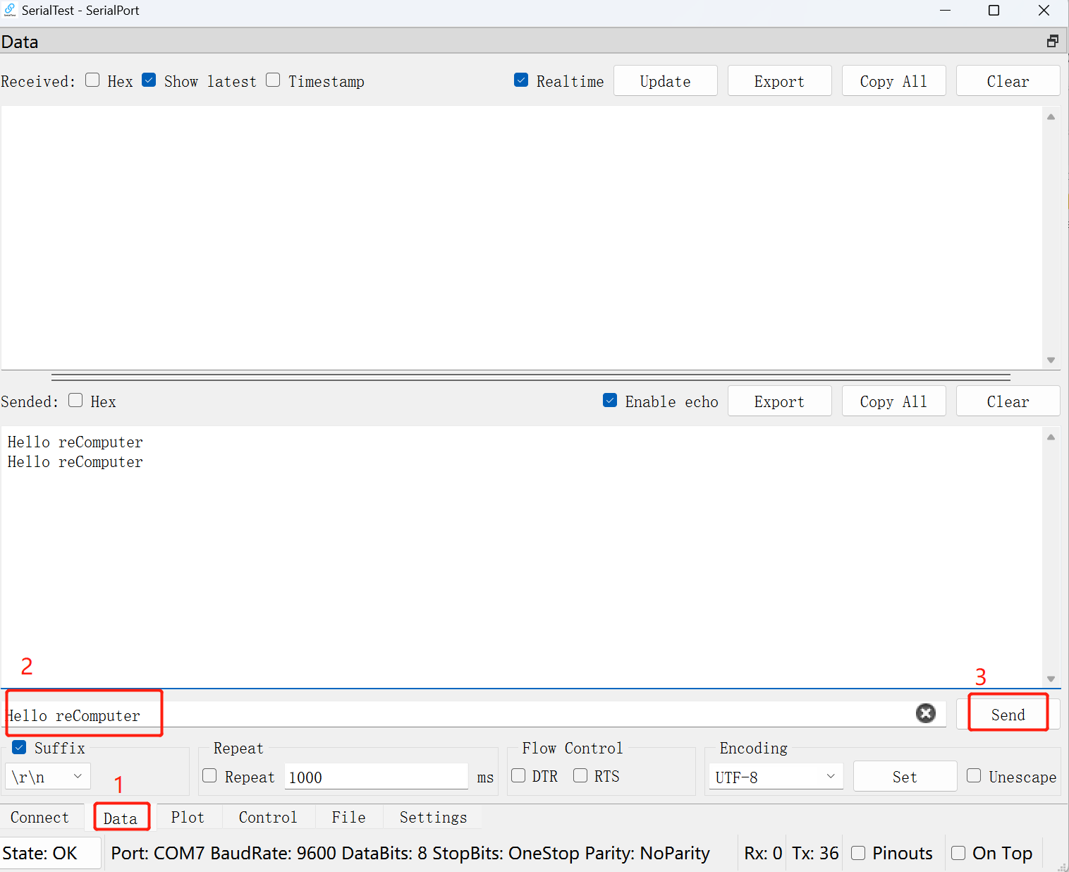
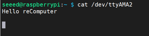
By default, the power enable port of the RS485 port is high. And each RS485 interface is in the accepting state. You can do a simple experiment.
The 485 port that connects the pc to the reComputer-R.
Enter in the terminal of reComputer:
cat /dev/ttyAMA2
Then send some data in the serial debugging tool of your computer, you can observe the data in the terminal window of reComputer.
Boot Switch

The Boot Switch of the reComputer R1000 is connected to the nRPI_BOOT pin of CM4. This switch provides users with the option to select the boot source between eMMC and USB. In normal mode, the switch should be set away from the side with the "BOOT" label, enabling the system to boot from eMMC. Conversely, when users need to flash the system image, they should set the switch towards the "BOOT" label, allowing the system to boot from the Type-C USB interface.
| Switch Position | Mode | Description | nRPI-BOOT |
|---|---|---|---|
 | Normal mode | Boot from eMMC | Low |
| Flash mode | Boot from USB | High |
USB

The reComputer R1000 is equipped with one USB Type-C port and two USB Type-A ports. Please refer to the table below for their functions and descriptions.
| Type | Quantity | Protocol | Function | Description |
|---|---|---|---|---|
| Type-C | *1 | USB2.0 | USB-Device | Used for serial port debugging, burning image, etc. |
| Type-A | *2 | USB2.0 | USB-Host | Connect different USB devices such as flash drives, USB keyboards or mouses. |
Check if the USB hub is detected by running the lsusb command. This command lists all connected USB devices, including hubs.
lsusb
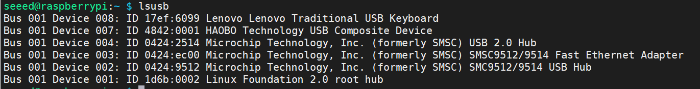
Running this command should display information about the USB devices connected to your system, including any USB hubs that are present.
If the USB hub is functioning properly, you should see its details listed in the output of the lsusb command. If it's not listed, there may be an issue with the hub or its connection to the system. In such cases, you may need to troubleshoot the USB hub or its connections.
SIM Slot
The reComputer R1000 uses a standard-size SIM card slot commonly found in industrial applications, which requires a standard SIM card with dimensions of 25mm x 15mm.
Please note that the standard version of reComputer R1000 does not come with a 4G module. If you require 4G functionality, an additional 4G module must be purchased separately.
SSD Slot
The SSD slot on the reComputer R1000 is designed to accommodate NVMe M.2 2280 SSDs for 128GB, 256GB, 512GB and 1TB in capacity. This slot allows for high-speed storage expansion, enabling users to enhance the performance and capacity of their system.
To list the disks, including the SSD, you can use the fdisk -l command. Here's how:
sudo fdisk -l
This command will display a list of all disks connected to your system, including the SSD if it's properly detected. Look for entries that represent your SSD. They typically start with /dev/sd followed by a letter (e.g., /dev/sda, /dev/sdb, etc.). Once you identify the entry corresponding to your SSD, you can proceed with partitioning or formatting it as needed.
There are two main uses for SSD cards:
1.High Capacity Storage: SSD cards can be utilized for high-capacity storage needs.
2.Boot Drive with Image: Another usage involves using the SSD both as a high-capacity storage and for storing system images, allowing booting directly from the SSD card.
It's important to note that not all SSD cards available in the market support the second usage. Therefore, if you intend to use it as a boot drive and are unsure about which model to purchase, we recommend opting for our recommended 1TB SSD(SKU 112990267). This model has been tested and verified for boot functionality, reducing the risk of compatibility issues and minimizing trial and error costs.
Mini-PCle Slot
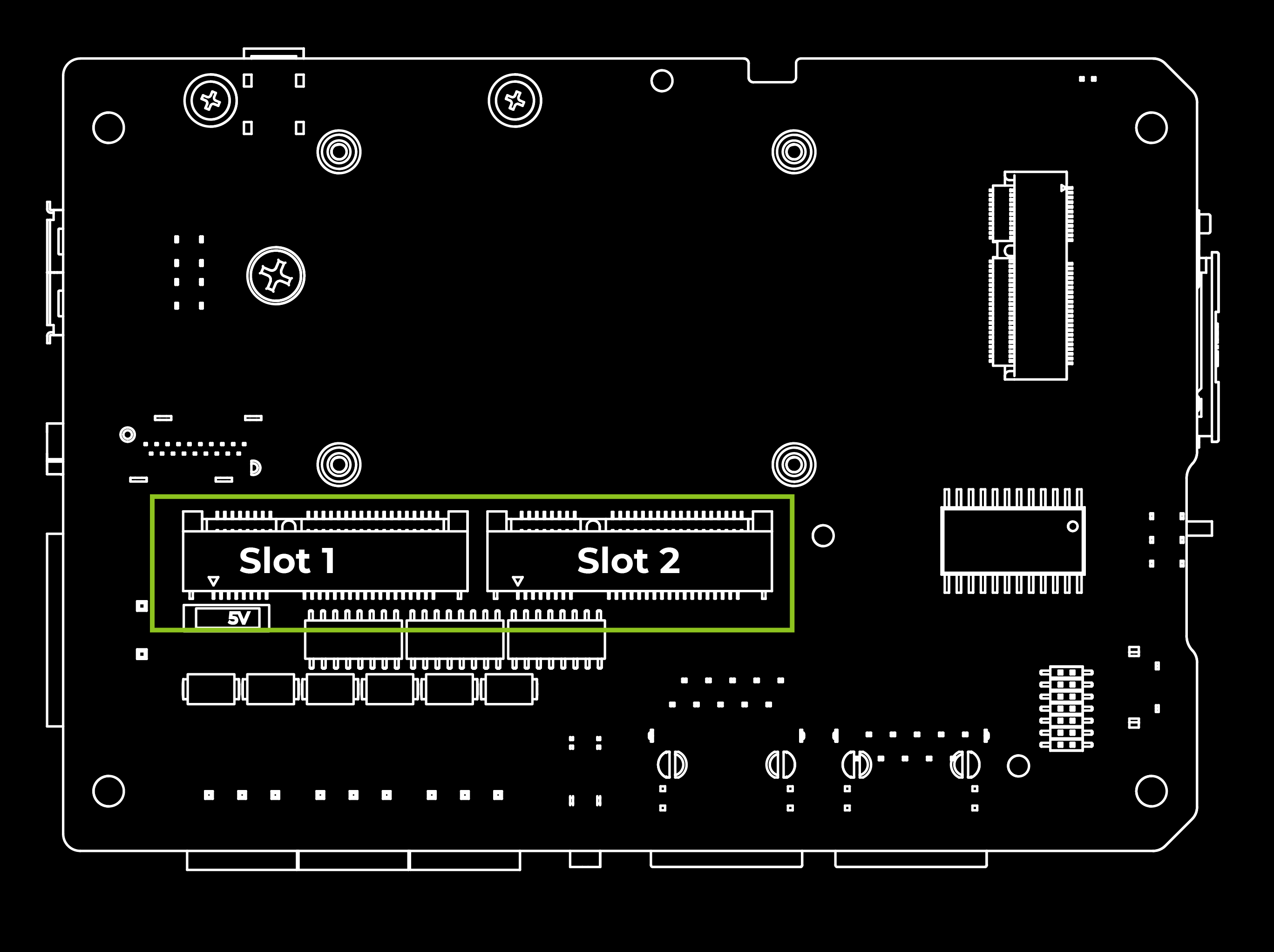
| Slot | Supported Protocol |
|---|---|
| Mini-PCIe 1 | 4G LTE |
| USB LoRa® | |
| Mini-PCIe 2 | SPI LoRa® |
| USB LoRa® |
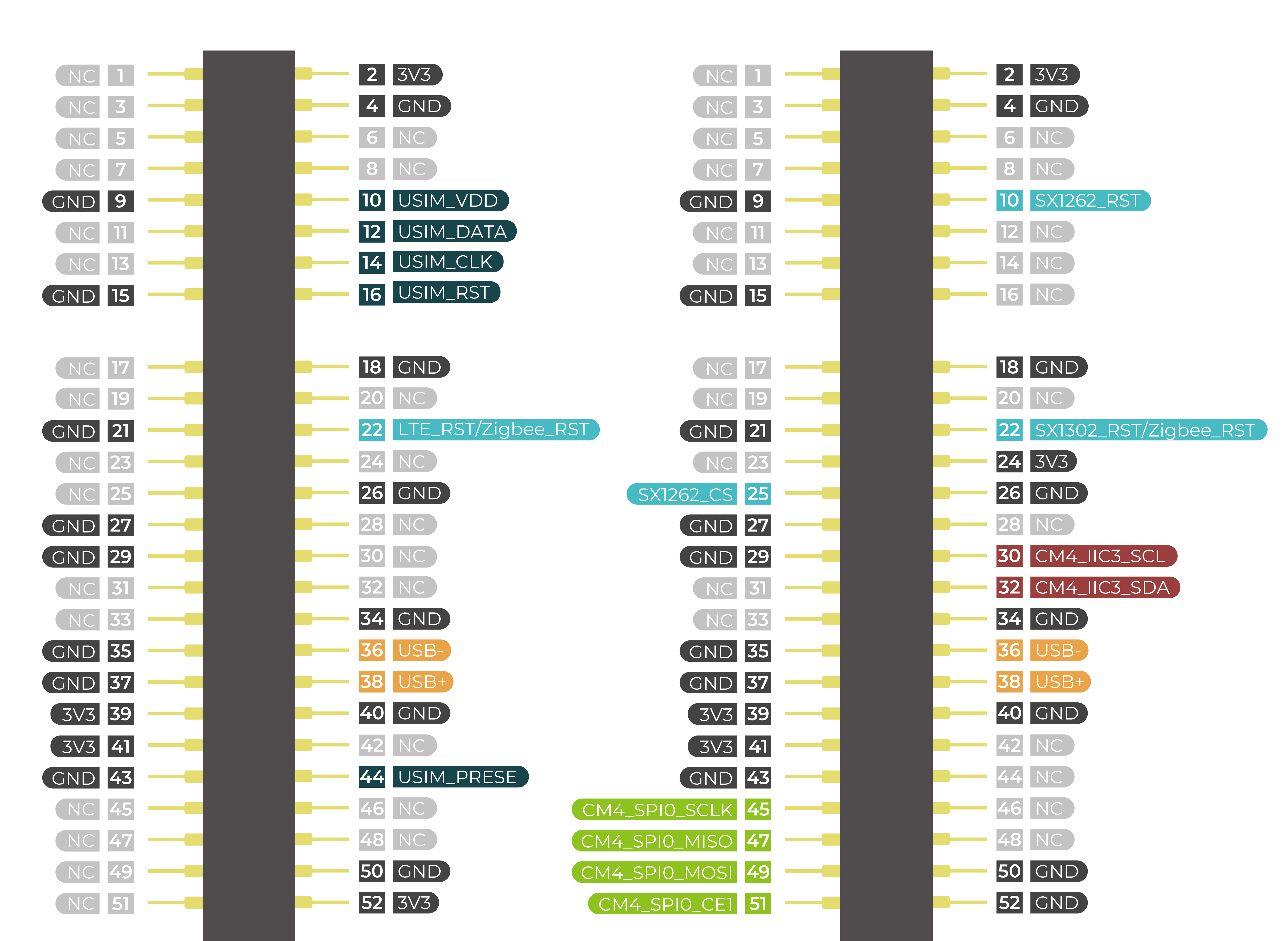
This device features two Mini-PCIe interfaces, namely Mini-PCIe Slot 1 and Mini-PCIe Slot 2. Slot 1 connects to SIM card slot and supports USB protocols, while Slot 2 supports both USB and SPI protocols but doesn't connect to SIM card slot. Therefore, devices such as 4G LTE and USB LoRa® can be connected through Slot 1, while SPI LoRa® and USB LoRa® devices can be connected through Slot 2.
Reset Hole

There is a Mini Push Button Switch located in the reset hole of reComputer R1000. By pressing this button with a thin object, the CM4 can be reset. This pin when high signals that the CM4 has started. Driving this pin low resets the module.
Ethernet RJ45

| Name | Type | Speeds | PoE |
|---|---|---|---|
| ETH0 | CM4 native Gigabit Ethernet | 10/100/1000 Mbit/s | Supported (with additional module) |
| ETH1 | Converted from USB | 10/100 Mbit/s | Not Supported |
The reComputer R1000 comes with two Ethernet RJ45 ports. ETH0 is a CM4 native Gigabit Ethernet interface that supports three different speeds: 10/100/1000 Mbit/s. An additional PoE module can be purchased to enable power-over-Ethernet (PoE) delivery through this interface, providing power to the reComputer R1000. Another one ETH1 supports 10/100 Mbit/s which is converted from USB.
HDMI

The reComputer R1000 features a native HDMI interface from CM4, supporting up to 4K @ 60 fps video output. It is ideal for applications that require multiple displays, allowing users to output their content to external large screens.
RTC
The reComputer R1000 features an RTC circuit that comes pre-installed with a CR2032 battery, enabling it to maintain timekeeping functionality even in the event of power loss.
To test the Real-Time Clock (RTC) functionality, follow these steps:
- Disable automatic time synchronization:
sudo systemctl stop systemd-timesyncd
sudo systemctl disable systemd-timesyncd
- Set the time to 12:00 PM on March 20, 2024:
sudo hwclock --set --date "2024-03-20 12:00:00"
- Synchronize the RTC time to the system:
sudo hwclock --hctosys
- Check the RTC time:
sudo hwclock -r
This command will read and display the time stored in the RTC. 5. Disconnect the power source from the RTC, wait a few minutes, then reconnect it and check the RTC time again to see if it retained the correct time.
Watchdog
The reComputer R1000 comes equipped with an independent hardware watchdog circuit that ensures automatic system reboot in case of abnormal system crashes. The watchdog circuit is implemented through RTC and allows for flexible feeding times from 1 to 255 seconds.
To perform a watchdog test, follow these steps:
- Install the watchdog software:
sudo apt install watchdog
- Edit the watchdog configuration file:
# make sure you install vim already, if haven't, can install by the command below
sudo apt-get install vim
sudo vim /etc/watchdog.conf
Modify the configuration as follows:
watchdog-device  = /dev/watchdog
# Uncomment and edit this line for hardware timeout values that differ
# from the default of one minute.vi
watchdog-timeout = 120
# If your watchdog trips by itself when the first timeout interval
# elapses then try uncommenting the line below and changing the
# value to 'yes'.
#watchdog-refresh-use-settimeout = auto
# If you have a buggy watchdog device (e.g. some IPMI implementations)
# try uncommenting this line and setting it to 'yes'.
#watchdog-refresh-ignore-errors = no
# ====================== Other system settings ========================
#
# Interval between tests. Should be a couple of seconds shorter than
# the hardware time-out value.
interval  = 15
max-load-1  = 24
#max-load-5  = 18
#max-load-15  = 12
realtime  = yes
priority  = 1
You can adjust other settings as needed. 3. Ensure the watchdog service is running:
sudo systemctl start watchdog
- To test the watchdog functionality, execute the following command to simulate a system hang:
sudo su
echo 1 > /proc/sys/kernel/sysrq
echo "c" > /proc/sysrq-trigger
This command triggers a kernel crash and should cause the watchdog to reboot the system.
- Monitor the system to confirm that it reboots after the specified timeout period. These steps will help you test and ensure the functionality of the watchdog timer on your system.
Optional Interfaces and Modules
The reComputer R1000 supports a rich selection of expansion modules and accessories, making it suitable for a wide range of scenarios and requirements. If you are interested in customizing the reComputer R1000, please [email protected] for more information. Here is the accessories and optional modules list:
| Remark | Item | Product Name | SKU |
| Must be used together for LoRa®WAN Function | LoRa® Module | Region optional LoRaWAN Gateway Module(SPI)-US915 | 114992969 |
| Region optional LoRaWAN Gateway Module(SPI)-EU868 | 114993268 | ||
| Region optional LoRaWAN Gateway Module(USB)-US915 | 114992991 | ||
| Region optional LoRaWAN Gateway Module(USB)-EU868 | 114992628 | ||
| LoRa® Antenna | LoRa Antenna Kit - 868-915 MHz | 110061501 | |
| This accessory is required for Wi-Fi function | Wi-Fi/BLE Antenna | Raspberry Pi Compute Module 4 Antenna Kit | 114992364 |
| 4G antenna with 4G module for 4G function, GPS antenna with 4G module for GPS function | 4G module | LTE Cat 4 EC25-AFXGA-Mini-PCIe Module - for North American | 113991134 |
| LTE Cat 4 EC25-EUXGR-Mini-PCIe Module - for EMEA and Thai | 113991135 | ||
| LTE Cat 4 EC25-AUXGR-Mini-PCIe Module - for Australia | 113991174 | ||
| LTE Cat 4 EC25-EFA-Mini-PCIe Module - for Thai | 113991214 | ||
| LTE Cat 4 EC25-EMGA-Mini-PCIe Module - for Malaysia | 113991234 | ||
| LTE Cat 4 EC25-JFA-mini-PCIe | 113991296 | ||
| 4G Antenna | 4G Antenna Kit for 4G module | 110061502 | |
| GPS Antenna | GPS Antenna Kit for EC25 4G Module | 110061521 | |
| Encryption Chip TPM 2.0 | TPM 2.0 Module with infineon SLB9670 | 114993114 | |
| SSD card | NVMe M.2 2280 SSD 1TB | 112990267 | |
| 512GB NVMe M.2 PCle Gen3x4 2280 Internal SSD | 112990247 | ||
| 256GB NVMe M.2 PCle Gen3x4 2280 Internal SSD | 112990246 | ||
| 128GB NVMe M.2 PCle Gen3x4 2280 Internal SSD | 112990226 | ||
| This module needs to be soldered onto the carrier board of the reComputer R1000 | PoE | MQ7813T120 PoE Module Kit for reTerminal DM | 110991925 |
| UPS | SuperCAP UPS LTC3350 Module | 110992004 |
The reComputer R1000 mainboard features two Mini-PCIe slots. Mini-PCIe slot 1 supports 4G module and LoRa® module using the USB protocol; while Mini-PCIe slot 2 supports LoRa® module using the USB and SPI protocol.
Can not plug in 2 LoRa® modules on board.
Wi-Fi/BLE
The reComputer R1000-10 is powered by the CM4 with an onboard Wi-Fi/BLE version, providing the same Wi-Fi/BLE parameters as the CM4. For detailed parameter information, please refer to the Raspberry Pi official website.
It is important to note that due to the reComputer R1000's metal casing, Wi-Fi/BLE signals may have difficulty penetrating the metal exterior. If you require Wi-Fi/BLE functionality, it is recommended to purchase an external antenna and click here for assemble instruction.
Connect wifi
step1. To scan for Wi-Fi networks:
nmcli dev wifi list
step2. Connect to the wifi network:
sudo nmcli dev wifi connect network-ssid password "network-password"
sudo nmcli --ask dev wifi connect network-ssid #If you don't want to write your password on the screen, you can use the --ask option.
step3. After the device is powered on, it will automatically connect to wifi. If you want to delete the saved WiFi information:
nmcli con del network-ssid
After the connection is disconnected, connect to another wifi.
Connect bluetooth devices
Before adding a Bluetooth device, the Bluetooth service on your computer must be started and running. You can check this with the systemctl command.
sudo systemctl status bluetooth
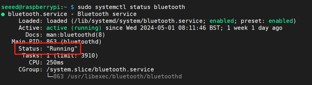
If the Bluetooth service status is not active, you must enable it first. Then start the service so that it starts automatically when you start your device.
sudo systemctl enable bluetooth
sudo systemctl start bluetooth
You can use the bluetoothctl tool to connect and manage Bluetooth, the following are some common commands and comments:
#Scan attachments to the device
bluetoothctl scan on

#To make your Bluetooth adapter discoverable to other devices, use the following command:
bluetoothctl discoverable on


#Replace A4:C1:38:F4:83:2E below with the Media Access Control (MAC) address you want to connect to
#Pair a new Bluetooth device
bluetoothctl pair A4:C1:38:F4:83:2E

#Connect previously paired devices
bluetoothctl connect A4:C1:38:F4:83:2E

#View the list of devices paired with the system
bluetoothctl paired-devices

#When a Bluetooth device is trusted, the system automatically connects to it after discovering it
bluetoothctl trust A4:C1:38:F4:83:2E

#Cancel trust
bluetoothctl untrust A4:C1:38:F4:83:2E

#Remove a paired Bluetooth device
bluetoothctl remove A4:C1:38:F4:83:2E

#Disconnect the Bluetooth connection, but do not remove it from the paired list
bluetoothctl disconnect A4:C1:38:F4:83:2E

#Block specific devices from connecting to your system
bluetoothctl block A4:C1:38:F4:83:2E

#Unblock device
bluetoothctl unblock A4:C1:38:F4:83:2E


#Use interactive mode and exit
bluetoothctl
exit
4G Module

The reComputer R1000 mainboard features two Mini-PCIe slots, with Mini-PCIe slot 1 supporting a 4G module using the USB protocol. The EC25 4G module from Quectel has been fully tested to be compatible with the reComputer R1000.
Please note that if you require 4G functionality, it is necessary to purchase the corresponding 4G module and external antenna. Please click here for assemble instruction.
Connect to 4G module by ECM mode
To interact with a 4G module using AT commands via minicom, follow these steps:
Step 1. Please put in the 4G enabled sim-card in the sim card slot, before you power up the system.
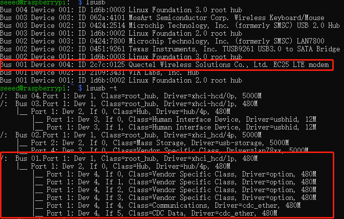
Step 2. Check if EC25-EUX gets detectd by using lsusb
lsusb
lsusb -t
Step 3. Install the serial communication tool minicom.
sudo apt install minicom
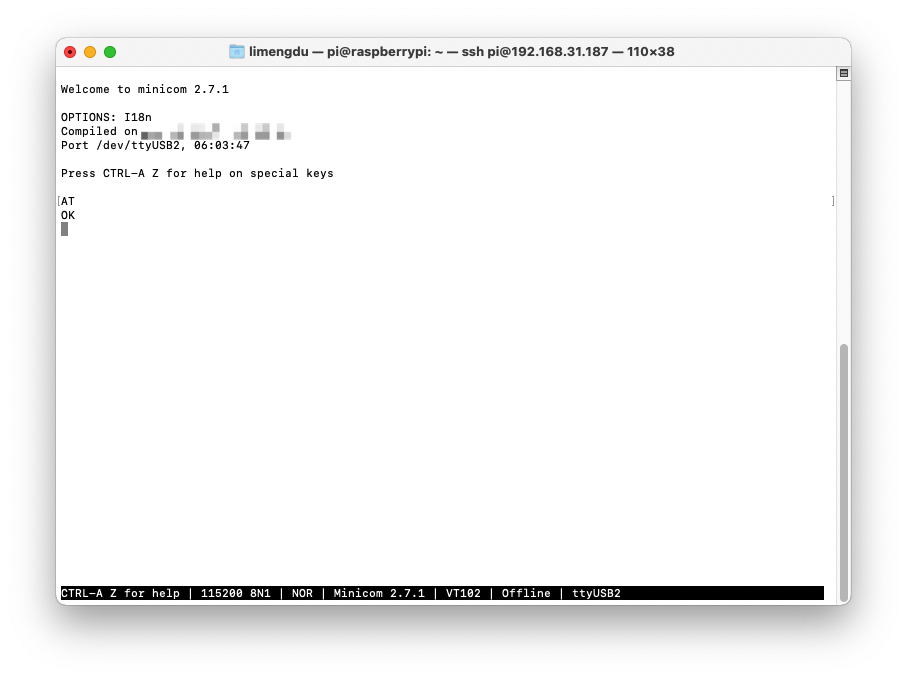
Step 4. Connect EC25-EUX 4G module through minicom.
sudo minicom -D /dev/ttyUSB2 -b 1152008n1
once the serial connection opened, Type in AT and press 'Enter', and you should see OK.
Step 5. Enable 4G module to connect to 4G network
AT the same minicom serial window please type:
AT+QCFG="usbnet"
It will return something like +QCFG: "usbnet",0, but we need that to be set to 1 (ECM mode), so enter the following command:
AT+QCFG="usbnet",1
Then enter the following command to force the modem to reboot:
AT+CFUN=1,1
Then you could reboot or wait for a while for the moudel to get internet from your sim card carrier.
You can also use the command ifconfig to query the networking status of reComputer R1000.
ECM mode will create a new network interface usb0 for you to use.
Connect to 4G module by QMI mode
To interact with a 4G module using QMI protocol via qmicli, follow these steps:
Step 1. Download the quectel-CM tool to the /usr/bin/ directory.
# Use wget to download the compiled quectel-CM to /usr/bin/
sudo wget -O /usr/bin/quectel-CM https://files.seeedstudio.com/wiki/reComputer-R1000/network/quectel-CM
# Add execution permission
sudo chmod 777 /usr/bin/quectel-CM
Step 2. Set the 4G network card mode to QMI.
sudo minicom -D /dev/ttyUSB2 -b 115200

# Enter the following command
AT+QCFG="usbnet",0
# Enter the following command to verify
AT+QCFG="usbnet"
# Successful configuration is indicated by the following response
AT+QCFG="usbnet",0

# Enter the command to restart and enable the module
AT+CFUN=1,1
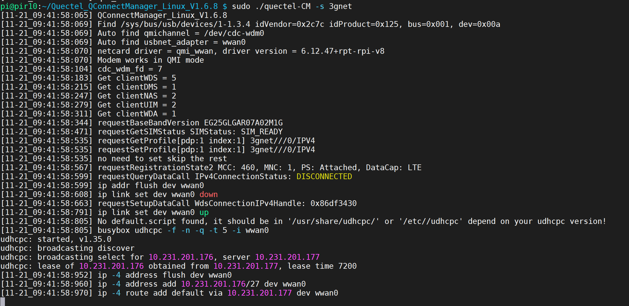
Step 3. Test the network connection.
# Use the -s parameter to specify the APN for the data connection
sudo ./quectel-CM -s APN

# APN settings for different carriers
China Mobile: "cmnet"
China Unicom: "3gnet"
China Telecom: "ctnet"
Enter ifconfig to check if an IP address has been assigned
After the network connection test is successful, you can create a systemd service to ensure that the 4G module is automatically connected when the system boots up.
Step 4. Create a systemd service file.
Create an auto-start script:
sudo vi /opt/auto_4G.sh
Enter the following content. The APN should be determined based on your SIM card's carrier. Here, 3gnet is the APN for China Unicom.
#!/bin/bash
sudo quectel-CM -s 3gnet
Add execution permission:
sudo chmod 0755 /opt/auto_4G.sh
Create an auto-start service file:
sudo vi /etc/systemd/system/auto_4G.service
Content of the service file:
[Unit]
Description = auto_4G daemon

[Service]
ExecStart = /opt/auto_4G.sh
Restart = always
Type = simple

[Install]
WantedBy = multi-user.target
Enable and start the auto_4G.service:
sudo systemctl enable auto_4G
sudo systemctl start auto_4G
Then you could reboot or wait for a while for the moudel to get internet from your sim card carrier.
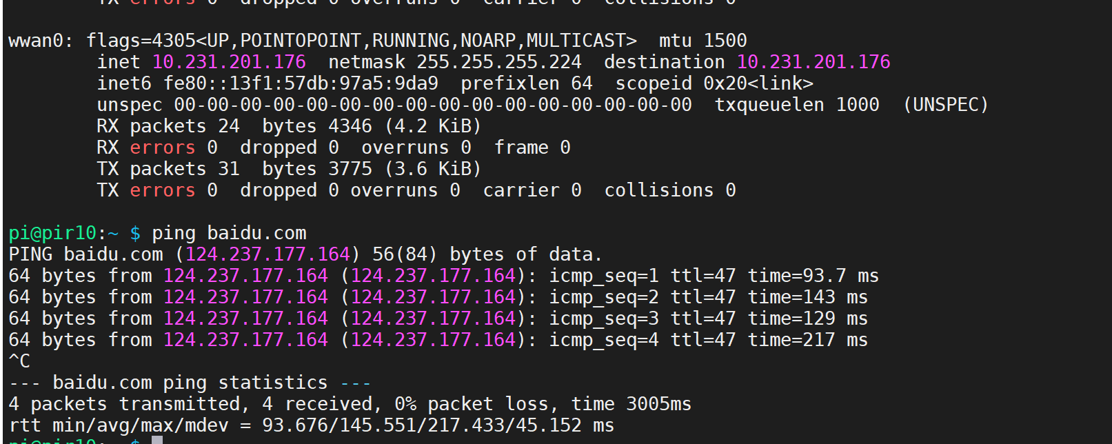
You can also use the command ifconfig to query the networking status of reComputer R1000.
QMI mode will create a new network interface wwan0 for you to use.
LoRa® Module
Both two Mini-PCIe slots supports LoRa® module using the USB protocol. Meanwhile, Mini-PCIe slot2 supports a LoRa® module using the SPI protocol. The WM1302 module from Seeed Studio has been fully tested to be compatible with the reComputer R1000. However the USB verison will need to uiltising the Mini PCIe designed for 4G Moudle which means if you want to use the both 4G Module and LoraWAN® Module Please choose SPI version of the WM1302 LoraWAN® Module.
Please note that if you require LoRa® functionality, it is necessary to purchase the corresponding LoRa® module and external antenna.
- WM1302 SPI Module
- WM1302 USB Module

Step 1. Please refer to the LoraWAN® Module Hardware assembly guide to install WM1302 SPI LoraWAN® Module into the LoraWAN® Mini PCIe slot which you should see the Lora slikscreen.
Step 2. type sudo raspi-config in command line to open Raspberry Pi Software Configuration Tool:
- Select Interface Options
- Select SPI, then select Yes to enable it
- Select I2C, then select Yes to enable it
- Select Serial Port, then select No for "Would you like a login shell..." and select Yes for "Would you like the serial port hardware..."
After this, please reboot Raspberry Pi to make sure these settings work.
Step 3. Download the WM1302 code to reComputer R1000 and compile it.
cd ~/
git clone https://github.com/Lora-net/sx1302_hal
cd sx1302_hal
sudo vim ./libloragw/inc/loragw_i2c.h
Change #define I2C_DEVICE "/dev/i2c-1" to #define I2C_DEVICE "/dev/i2c-3".
If you are using version 1.1 reComputer R1000 please change to #define I2C_DEVICE "/dev/i2c-6"
sudo make
Step 4. Copy the reset_lgw.sh script
vim ./tools/reset_lgw.sh
Modify the code:
SX1302_RESET_PIN=580     # SX1302 reset
SX1302_POWER_EN_PIN=578  # SX1302 power enable
SX1261_RESET_PIN=579     # SX1261 reset (LBT / Spectral Scan)
// AD5338R_RESET_PIN=13    # AD5338R reset (full-duplex CN490 reference design)
cp ./tools/reset_lgw.sh ./packet_forwarder/
Step 5. Modify the content of the global_conf.json.sx1250.EU868 configuration file:
cd packet_forwarder
vim global_conf.json.sx1250.EU868
Change "com_path": "/dev/spidev0.0" to "com_path": "/dev/spidev0.1"
If you are using version 1.1 reComputer R1000 please change to "com_path": "/dev/spidev1.1"
Step 6. Start LoraWAN® Module
Then run the following code to start LoraWAN® Module according to your WM1302 operation frequence version.
cd ~/sx1302_hal/packet_forwarder
./lora_pkt_fwd -c global_conf.json.sx1250.EU868

Step 1. Please refer to the LoraWAN® Module Hardware assembly guide to install WM1302 USB LoraWAN® Module into the 4G Mini PCIe slot which you should see the 4G slikscreen.
Step 2. type sudo raspi-config in command line to open Raspberry Pi Software Configuration Tool:
- Select Interface Options
- Select I2C, then select Yes to enable it
- Select Serial Port, then select No for "Would you like a login shell..." and select Yes for "Would you like the serial port hardware..."
After this, please reboot Raspberry Pi to make sure these settings work.
Step 3. Download the WM1302 code to reTerminal and compile it.
cd ~/
git clone https://github.com/Lora-net/sx1302_hal
cd sx1302_hal
sudo vim ./libloragw/inc/loragw_i2c.h
Change #define I2C_DEVICE "/dev/i2c-1" to #define I2C_DEVICE "/dev/i2c-3".
sudo make
Step 4. Copy the reset_lgw.sh script
vim ./tools/reset_lgw.sh
Modify the code:
SX1302_RESET_PIN=580     # SX1302 reset
SX1302_POWER_EN_PIN=578  # SX1302 power enable
SX1261_RESET_PIN=579     # SX1261 reset (LBT / Spectral Scan)
// AD5338R_RESET_PIN=13    # AD5338R reset (full-duplex CN490 reference design)
cp ./tools/reset_lgw.sh ./packet_forwarder/
Step 5. Load the WM1302-USB module
# Check the device
lsusb
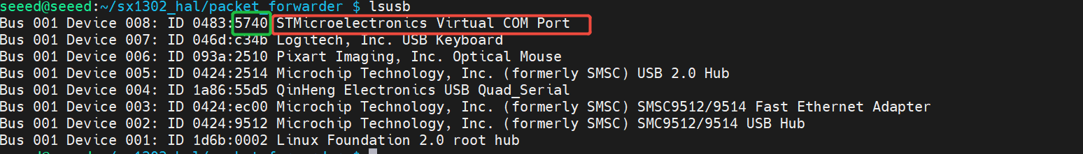
# Use the ID number to find the port number
sudo dmesg | grep 5740
# Load ACM module
sudo modprobe cdc_acm

Step 6. Find the device file
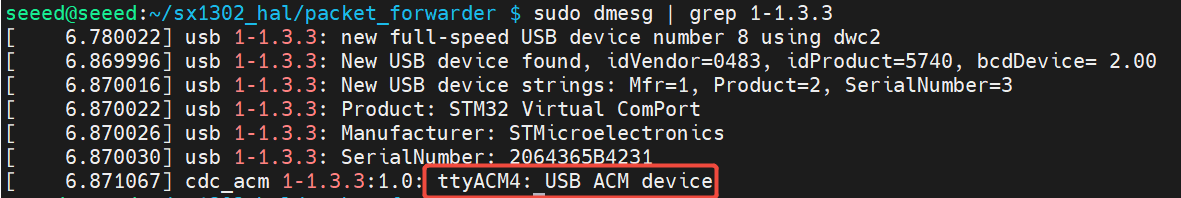
sudo dmesg | grep 1-1.3.3
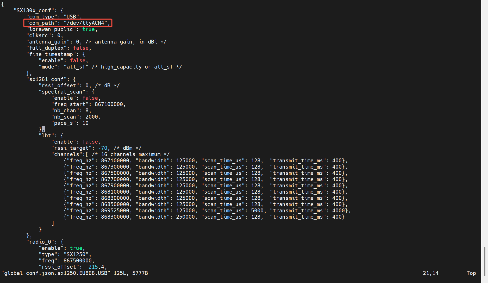
Step 7. Modify the content of the global_conf.json.sx1250.EU868.USB configuration file:
cd packet_forwarder
vim global_conf.json.sx1250.EU868.USB
Change "com_path": "/dev/ttyACM0" to "com_path": "/dev/ttyACM4"
Step 8. Start LoraWAN® Module
Then run the following code to start LoraWAN® Module according to your WM1302 operation frequence version.
cd ~/sx1302_hal/packet_forwarder
./lora_pkt_fwd -c global_conf.json.sx1250.EU868.USB
This command specifies the configuration file to be used for LoRa® USB.
PoE
The reComputer R1000 worked as powered devices can support the IEEE 802.3af standard by adding a PoE power supply module. Users need to disassemble the device to install the PoE module for Ethernet PoE function.
The reComputer R1000 supports PoE power supply, but the standard product does not include a PoE module by default. Seeed can provide PoE soldering and assembly services for batch customization orders. However, if a customer is testing a sample, they will need to solder and assemble the PoE module themselves.
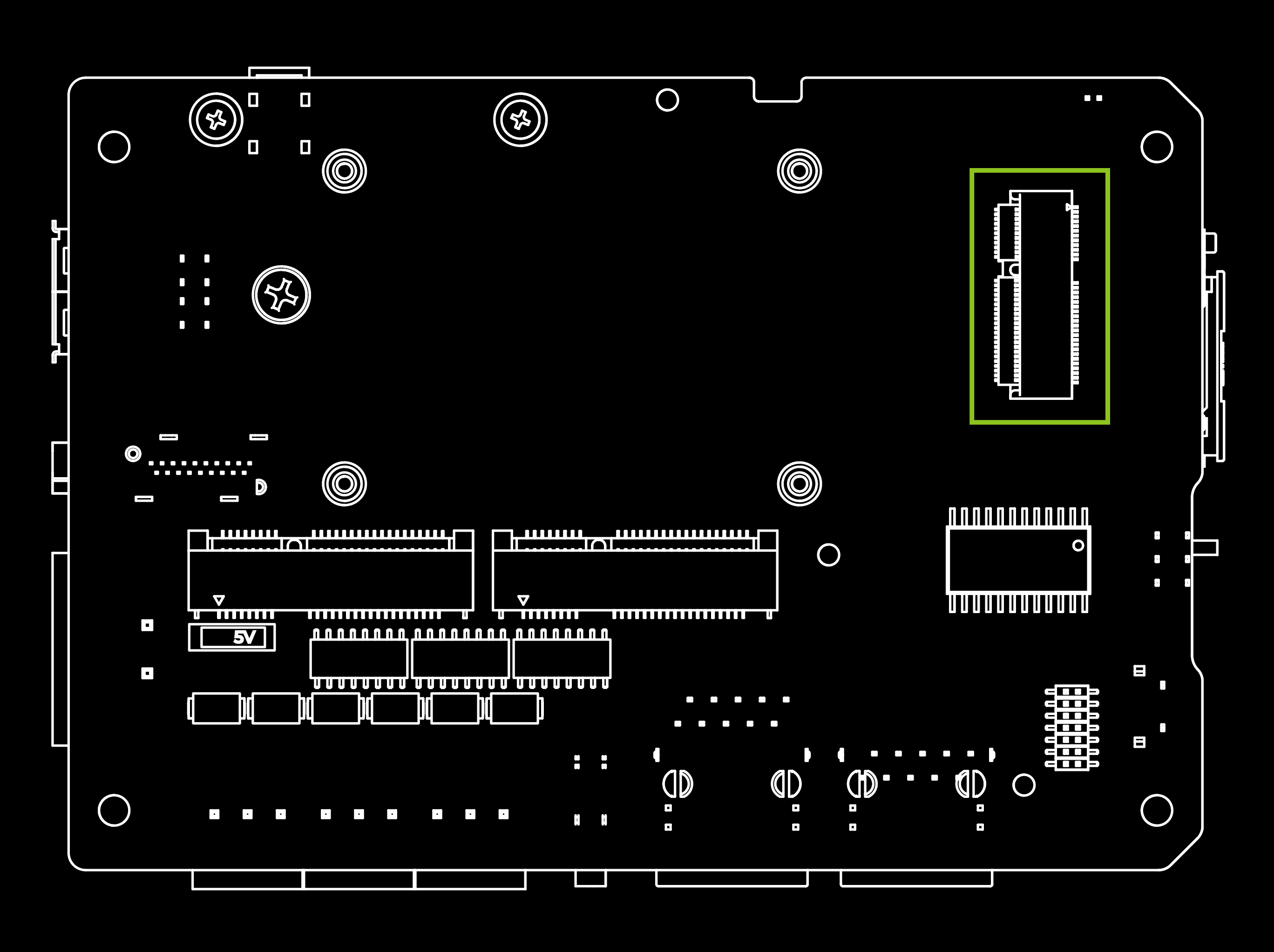
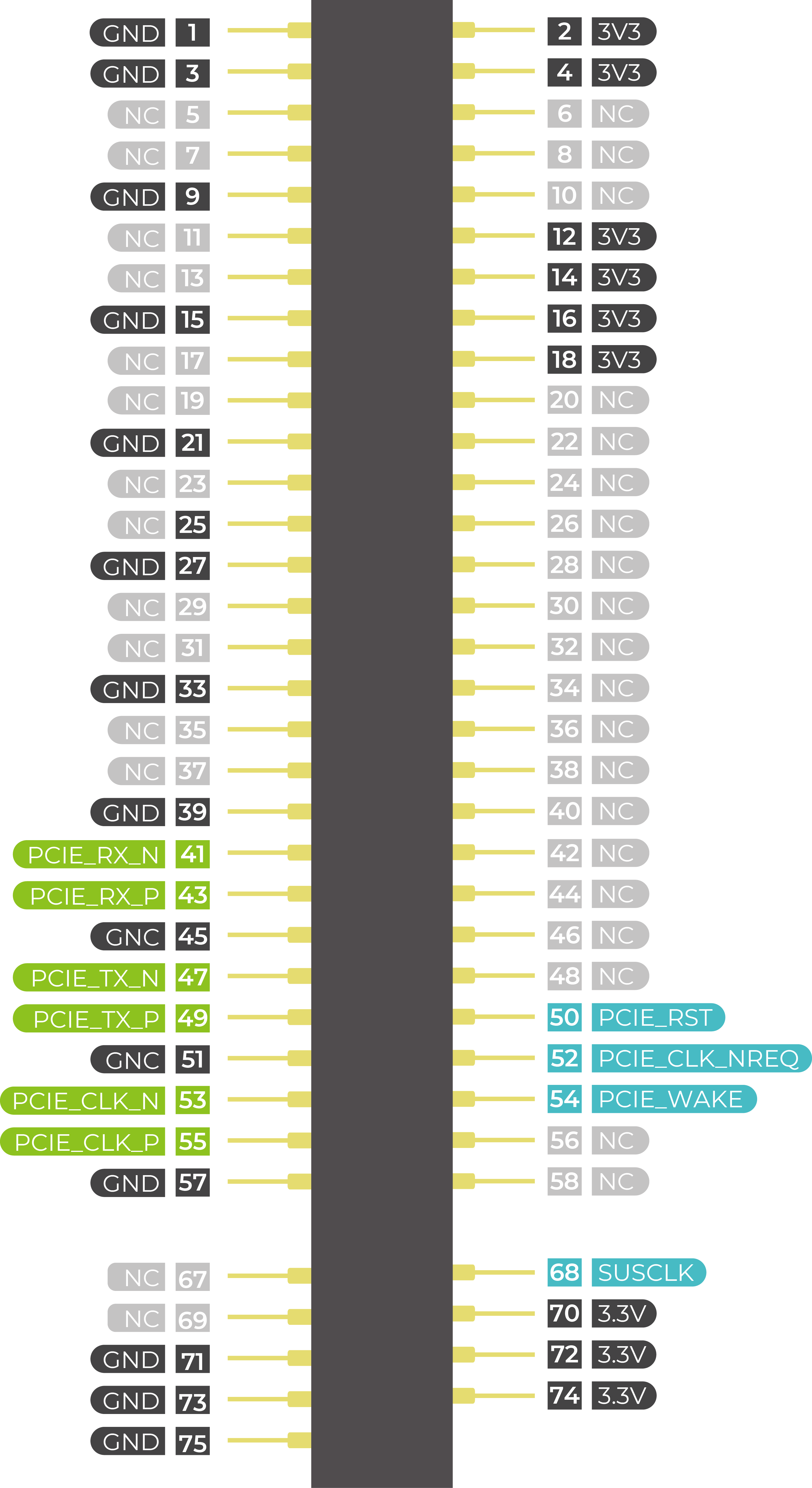
M.2 Slot
The reComputer R1000 supports 2280 NVMe SSD and AI accelerator(Hailo) through the use of a PCIe slot(J62) below two Mini-PCIe slots on board. It is important to note that the CM4's PCIe is gen2.0 with a maximum theoretical speed of 5Gbps. If you are using a Gen3.0 or higher SSD, it may not be able to achieve the SSD's maximum speed. After testing, the reTerminal DM with installed SSD can achieve a maximum write speed of 230MB/s and a maximum read speed of 370MB/s. If you are unsure which SSDs are compatible, you can purchase following the accessories list below.
Please click here for assemble instruction.
| SSD card | NVMe M.2 2280 SSD 1TB | 112990267 |
| 512GB NVMe M.2 PCle Gen3x4 2280 Internal SSD | 112990247 | |
| 256GB NVMe M.2 PCle Gen3x4 2280 Internal SSD | 112990246 | |
| 128GB NVMe M.2 PCle Gen3x4 2280 Internal SSD | 112990226 |
Please note that:
1- The speed test results may vary depending on the SSD model, testing method, and testing environment. The values provided here are for reference purposes only and were obtained in Seeed's laboratory.
There are two main uses for SSD cards:
1.High Capacity Storage: SSD cards can be utilized for high-capacity storage needs.
2.Boot Drive with Image: Another usage involves using the SSD both as a highcapacity storage and for storing system images, allowing booting directly from the SSD card.
It's important to note that not all SSD cards available in the market support the second usage. Therefore, if you intend to use it as a boot drive and are unsure about which model to purchase, we recommend opting for our recommended 1TB SSD(SKU 112990267). This model has been tested and verified for boot functionality, reducing the risk of compatibility issues and minimizing trial and error costs.
Encryption Chip TPM 2.0
The TPM features Infineon’s OPTIGA™ TPM SLB9670 which is compliant to the Trusted Computing Group (TCG) TPM 2.0 specification is recommened as encryption chip to the reComputer R1000. The chip features an SPI interface applied for port J13 on board, to enable a root of trust for platform integrity, remote attestation, and cryptographic services.
If you connect TPM 2.0 module to device, the following code can help check TPM connection.
ls /dev | grep tpm
If you see tpm0 and tpmrm0 in the output, it means that TPM (Trusted Platform Module) devices are detected and available on your system. This indicates that the TPM hardware is recognized and accessible, which is a good sign. You can proceed with using TPM-related functionalities or applications knowing that the devices are present and accessible.
UPS
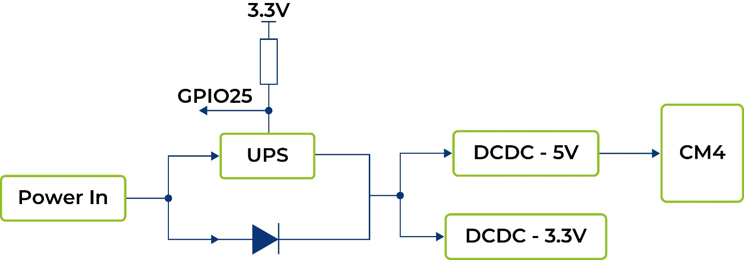
The UPS is 7F, which operates in series. The UPS module is positioned between the DC5V and CM4 components, with a GPIO signal utilized to alert the CPU in the event of a power loss from the 5V supply. Upon receiving this signal, the CPU executes an urgent script before the super capacitor's energy is depleted, initiating a "$ shutdown" command.
The backup duration provided by the UPS heavily relies on the system load. Below are some typical scenarios tested with a CM4 module featuring 4GB RAM, 32GB eMMC storage, and a Wi-Fi module.
| Mode of Operation | Time(s) | Remark |
|---|---|---|
| Idle | 37 | Testing under idle conditions with official driver program loaded |
| Full load of CPU | 18 | stress -c 4 -t 10m -v & |
For UPS function please contact us for more information, and the alarm signal is active LOW. Please click here for assemble instruction.
A GPIO25 between CPU and DC/AC power in is used to alarm CPU when the 5V power supply is down. Then the CPU should do something urgent in a script before energy exhaustion of super capacitor and run a $ shutdown
Another way to use this function is Initiate a shutdown when GPIO pin changes. The given GPIO pin is configured as an input key that generates KEY_POWER events. This event is handled by systemd-logind by initiating a shutdown.
Use /boot/overlays/README as reference, then modify /boot/config.txt.
dtoverlay=gpio-shutdown,gpio_pin=25,active_low=1
- For UPS function please contact us for more information.
- The alarm signal is active LOW.
The python code below is a demo for detecting the working mode of supercapacitor UPS through GPIO25, and automatically saving data and shut down when the system is powered off.
import RPi.GPIO as GPIO
import time,os

num = 0

GPIO.setmode(GPIO.BCM)
#set GPIO25 as input mode
#add 500ms jitter time for software stabilization
GPIO.setup(25,GPIO.IN,pull_up_down = GPIO.PUD_UP)
GPIO.add_event_detect(25,GPIO.FALLING, bouncetime = 500)
while True:
  if GPIO.event_detected(25):
    print('...External power off...')
    print('')
    os.system('sync')
    print('...Data saving...')
    print('')
    time.sleep(3)
    os.system('sync')
    #saving two times
    while num<5:
      print('-----------')
      s = 5-num
      print('---' + str(s) + '---')
      num = num + 1
      time.sleep(1)
    print('---------')
    os.system('sudo shutdown -h now')
DSI & Speaker
One DSI (J24)and one 4-pin Spearker (J7)interfaces are reserved on board, for special usage. Users are requested to purchase plug-ins according to your own needs.
Additional Resources
- User manual-reComputer R1000
- User manual-reComputer R1000 in Chinese
- reComputer R1000 3D File
- reComputer R1000 Schematic Desing, PCB Desing
- reComputer R1000 Flyer
- reComputer R1000 Flyer in Chinese
- reComputer R1000 v1.1 Pin Assignment
Resources
Tech Support & Product Discussion
Thank you for choosing our products! We are here to provide you with different support to ensure that your experience with our products is as smooth as possible. We offer several communication channels to cater to different preferences and needs.