Grove - Capacitive Moisture Sensor (Corrosion Resistant)
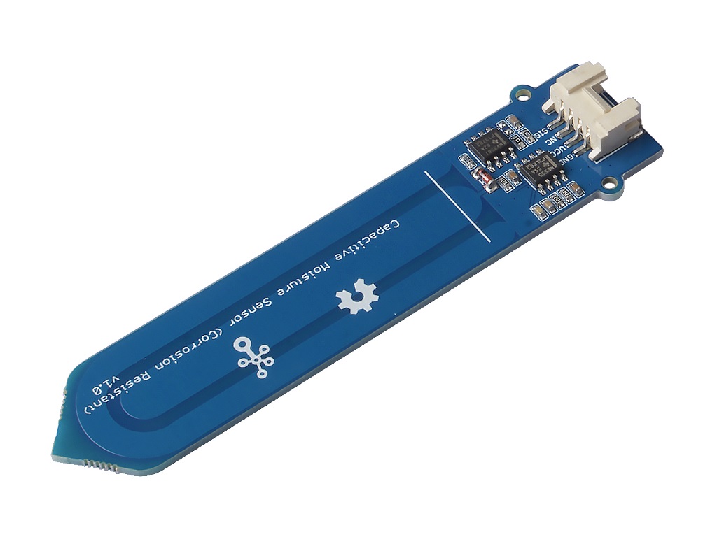
The Grove - Capacitive Moisture Sensor (Corrosion Resistant) is a soil moisture sensor based on capacitance changes. Compared with resistive sensors, capacitive sensors do not require direct exposure of the metal electrodes, which can significantly reduce the erosion of the electrodes. Hence, we call it Corrosion Resistant.
It is important to note that this sensor can only qualitatively test the humidity of the soil and cannot measure quantitatively. Which means when the humidity of the soil rises, the value of the output decreases; conversely, when the humidity decreases, the output value becomes higher.

Upgradable to Industrial Sensors
With the SenseCAP S2110 controller and S2100 data logger, you can easily turn the Grove into a LoRaWAN® sensor. Seeed not only helps you with prototyping but also offers you the possibility to expand your project with the SenseCAP series of robust industrial sensors.
SenseCAP S210x series industrial sensors provide an out-of-box experience for environmental sensing. Please refer to the S2105 Wireless Soil Moisture, Temperature, and EC Sensor with higher performance and robustness for soil condition monitoring. The series includes sensors for soil moisture, air temperature and humidity, light intensity, CO2, EC, and an 8-in-1 weather station. Try the latest SenseCAP S210x for your next successful industrial project.
| SenseCAP Industrial Sensor |
 |
| S2105 Soil Moisture & Temp & EC |
Version
| Product Version | Changes | Released Date |
|---|---|---|
| Grove - Capacitive Moisture Sensor (Corrosion Resistant) | Initial | Sep 2018 |
Feature
- Capacitive Style
- Corrosion Resistant
- Built-in Amplifier
Specification
| Item | Value |
|---|---|
| Operating Voltage | 3.3V / 5V |
| Output Interface | Analog |
| Length | 92.1mm |
| Width | 23.5mm |
| Height | 6.5mm |
| size | L: 40mm W: 20mm H: 13mm |
| Weight | 10.6g |
| Package size | L: 150mm W: 100mm H: 15mm |
| Gross Weight | 19g |
Typical Applications
- Soil moisture detection
- Automatic watering of plants
Hardware Overview
Pin Out
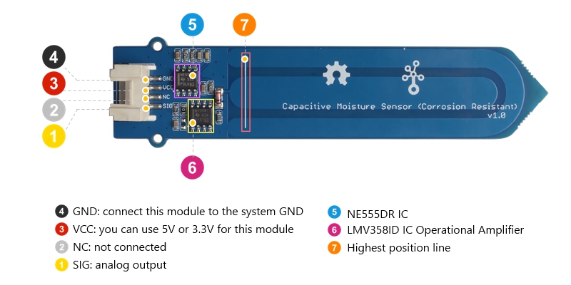
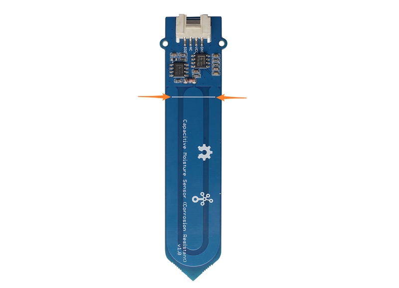
The part of the sensor inserted into the soil cannot exceed the highest position line.
Platforms Supported
| Arduino | Raspberry Pi | |||
|---|---|---|---|---|
The platforms mentioned above as supported is/are an indication of the module's hardware or theoritical compatibility. We only provide software library or code examples for Arduino platform in most cases. It is not possible to provide software library / demo code for all possible MCU platforms. Hence, users have to write their own software library.To do means not be supported now, may or may not be supported in the future.
Getting Started
Play With Arduino
Hardware
Materials required
| Seeeduino V4.2 | Base Shield | Grove - Capacitive Moisture Sensor |
|---|---|---|
 |  |  |
| Get One Now | Get One Now | Get One Now |
1 Please plug the USB cable gently, otherwise you may damage the port. Please use the USB cable with 4 wires inside, the 2 wires cable can't transfer data. If you are not sure about the wire you have, you can click here to buy
2 Each Grove module comes with a Grove cable when you buy. In case you lose the Grove cable, you can click here to buy.
1. If the you uses Arduino UNO as the motherboard, it is recommended that use the DC power supply. Otherwise, the maximum ripple of VCC may exceed 100mV. If you use Seeeduino V4.2 as the motherboard, you do not need to connect DC power.
2. Hot swap is not supported.
-
Step 1. Connect the Grove - Capacitive Moisture Sensor to port A0 of Grove-Base Shield.
-
Step 2. Plug Grove - Base Shield into Seeeduino.
-
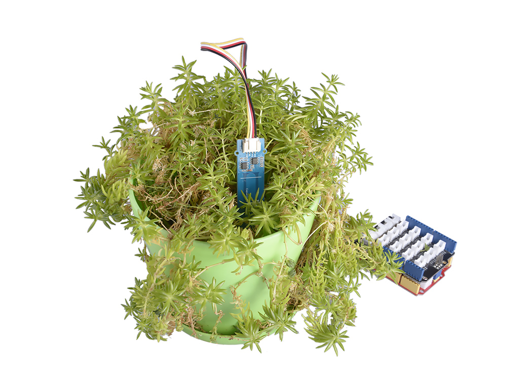
Step 3. Insert the Grove - Capacitive Moisture Sensor into the soil to be tested.
The part of the sensor inserted into the soil cannot exceed this white line.
- Step 4. Connect Seeeduino to PC via a USB cable.
If we don't have Grove Base Shield, We also can directly connect this module to Seeeduino as below.
| Seeeduino | Grove Cable | Grove - Capacitive Moisture Sensor |
|---|---|---|
| GND | Black | GND |
| 5V or 3.3V | Red | VCC |
| Not connection | White | NC |
| A0 | Yellow | SIG |
Software
If this is the first time you work with Arduino, we strongly recommend you to see Getting Started with Arduino before the start.
Step 1. Copy the code below, and download it to your arduino. If you do not know how to upload the code, please check How to upload code.
/*
  AnalogReadSerial

  Reads an analog input on pin 0, prints the result to the Serial Monitor.
  Graphical representation is available using Serial Plotter (Tools > Serial Plotter menu).
  Attach the center pin of a potentiometer to pin A0, and the outside pins to +5V and ground.

  This example code is in the public domain.

  https://arduino.cc/en/Tutorial/AnalogReadSerial
*/

// the setup routine runs once when you press reset:
void setup() {
  // initialize serial communication at 9600 bits per second:
  Serial.begin(9600);
}

// the loop routine runs over and over again forever:
void loop() {
  // read the input on analog pin 0:
  int sensorValue = analogRead(A0);
  // print out the value you read:
  Serial.println(sensorValue);
  delay(100);        // delay in between reads for stability
}
- Step 2. Open the Serial Monitor of Arduino IDE by click Tool-> Serial Monitor. Or tap the ++ctrl+shift+m++ key at the same time. Set the baud rate to 9600.
If every thing goes well, when you open the Serial Monitor it may show as below:
678
663
631
615
615
624
616
618
620
616
614
614
610
614
614
616
615
612
605
Due to individual differences in components, different module measurements in the same environment may vary.
Play with Raspberry Pi
If you want to use this module with Raspberry Pi, you may need to use any of the following hat:
- 4-Channel 16-Bit ADC for Raspberry Pi(ADS1115)
- 8-Channel 12-Bit ADC for Raspberry Pi (STM32F030)
- Grove Base Hat for Raspberry Pi
- Grove Base Hat for Raspberry Pi Zero
And you can find the demo in the wiki of those hats.
Schematic Online Viewer
Resources
-
[Zip] Grove - Capacitive Moisture Sensor (Corrosion Resistant) Eagle Files
-
[PDF] NE555DR Datasheet
-
[PDF] PDF Format Wiki
Tech Support & Product Discussion
Thank you for choosing our products! We are here to provide you with different support to ensure that your experience with our products is as smooth as possible. We offer several communication channels to cater to different preferences and needs.