Grove - Wio-E5
LoRaWAN® is a mark used under license from the LoRa Alliance®. The LoRa® Mark is a trademark of Semtech Corporation or its subsidiaries.
Grove Wio-E5 embedded with Wio-E5 STM32WLE5JC, powered by ARM Cortex M4 ultra-low-power MCU core and Wio SX126x, is a wireless radio module supporting LoRa® and LoRaWAN® protocol on the EU868 & US915 frequency and (G)FSK, BPSK, (G)MSK, LoRa® modulations. Grove - Wio-E5 can endow your development boards' strong features of ultra-long transmitting range by easily plug and play with Grove connector on board.
As an upgrade of our old version - Grove - Long Range 868MHz - powered by RFM95 ultra-long-range Transceiver Module, Grove LoRa-E5 embedded with Wio-E5 STM32WLE5JC Module is a high-performance and easy-to-use wireless radio LoRa® module supporting LoRaWAN® protocol.
Wio-E5 LoRaWAN® STM32WLE5JC module is the major functional part integrated into Grove - Wio-E5. It is a LoRaWAN® module that embedded with ARM Cortex M4 ultra-low-power MCU core and Wio SX126x, as the world-first combo of LoRa® RF and MCU chip into one single tiny module, it supports (G)FSK, BPSK, (G)MSK, and LoRa® modulations, and is FCC, CE certified. (Learn more about Wio-E5 from Wio-E5 wiki)
More comparison between the Wio-E5 and RFM95 chip:
By connecting Grove - Wio-E5 to your development boards, your devices are able to communicate with and control Wio-E5 conveniently by AT command through UART connection. Grove LoRa-E5 will be a superior choice for IoT device development, testing, and long-distance, ultra-low power consumption IoT scenarios like smart agriculture, smart office, and smart industry. It is designed with industrial standards with a wide working temperature at -40℃ ~ 85℃, high sensitivity between -116.5 dBm and -136 dBm, and power output between 10 dBm and 22 dBm.
Features
- Wio-E5 (STM32WLE5JC) embedded
- Support LoRaWAN® protocol on EU868/US915 frequency band
- Ultra-long transmitting range up to 10km (Ideal value in open space)
- Easy control by AT command via UART connection
- Rapid prototyping with plug-and-play Grove interfaces
- Ultra-low power consumption and high performance
Harware Overview
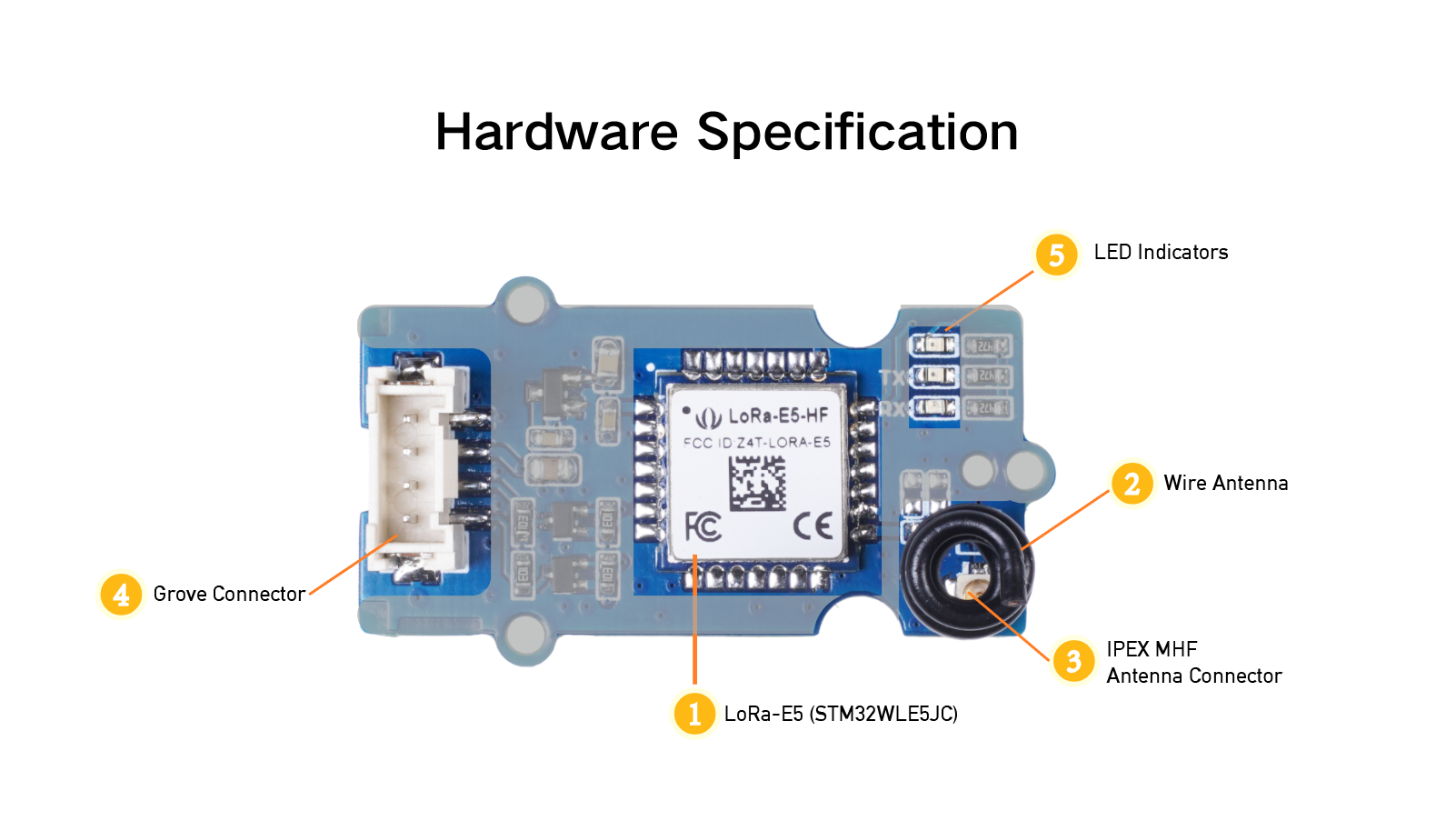
Wio-E5 STM32WLE5JC (Datasheet)
MHF IPEX Connector
Wire Antenna
Grove Connector
LED Indicators
Platform Supported
Arduino | Raspberry Pi | |||
---|---|---|---|---|
![]() | ![]() | ![]() |
Specification
General Parameters | |
---|---|
Voltage Supply: | 3.3V - 5V |
Power Output: | Up to +20 dBm at 3.3V |
Working Frequency | 868/915MHz |
Protocol | LoRaWAN® |
Sensitivity | -116.5dBm ~ -136dBm |
Modulation | LoRa®, (G)FSK, (G)MSK and BPSK |
Current | Only 60uA in sleep mode |
Size | 20*40mm |
Working Temperature | -40℃ ~ 85℃ |
Part List: | |
---|---|
Grove - Wio-E5 PCBA *1 | |
Grove Universal Cable*1 |
Application
Works for LoRaWAN® sensor nodes and any wireless communication application
IoT device testing and development
Application Notes
1. Factroy AT Firmare
Wio-E5 series has a built-in AT command firmware, which supports LoRaWAN® Class A/B/C protocol and a wide frequency plan: EU868/US915/AU915/AS923/KR920/IN865. With this AT command firmware, developers can easily and quickly build their prototype or application.
The AT command firmware contains a bootloader for DFU and the AT application. The "PB13/SPI_SCK/BOOT" pin is used to control Wio-E5 to stay in the bootloader or jump to the AT application. When PB13 is HIGH, the module will jump to AT application after reset, with a default baud rate of 9600. When PB13 is LOW (press the "Boot" button on Wio-E5 Dev Board or Wio-E5 mini), the module will stay in the bootloader, and keep transmitting "C" character every 1S at baud rate 115200.
- Factory AT Firmware is programmed with RDP(Read Protection) Level 1, developers need to remove RDP first with STM32Cube Programmer. Note that regression RDP to level 0 will cause a flash memory mass to erase and the Factory AT Firmware can't be restored again.
- The "PB13/SPI_SCK/BOOT" pin on the Wio-E5 module is just a normal GPIO, not the "BOOT0" pin of the MCU. This "PB13/SPI_SCK/BOOT" pin is used in the bootloader of the Factory AT firmware, to decide to jump to APP or stay in bootloader(for DFU). The real "BOOT0" pin doesn't pinout to the module, so users need to be careful when developing the low-power applications.
2. Clock Configuration
2.1 HSE
32MHz TCXO
TCXO power supply: PB0-VDD_TCXO
2.2 LSE
- 32.768KHz crystal oscillator
3. RF Switch
Wio-E5 module ONLY transmits through RFO_HP:
Receive: PA4=1, PA5=0
Transmit(high output power, SMPS mode): PA4=0, PA5=1
Getting Started
Preparations
Here is a demo showing you how to connect TTN (The Things Network) and Seeeduino XIAO module via Grove - Wio-E5 module. These modules are able to collect temperature and humidity parameters from the environment and send them back to TTN. The flashing LED lights on the Seeeduino Xiao indicate the status of the temperature and humidity sensor as connecting to TTN cloud.
Please ensure the consistent of the frequency band among the end nodes, gateway, and TTN configuration you are using by following this instruction. The frequency plan this demo applied is for EU868.
Hardware Required
Seeeduino XIAO | Grove - Wio-E5 | Seeeduino XIAO Expansion Board | Grove - Temperature & Humidity Sensor (DHT11) |
---|---|---|---|
If this is your first time using Seeeduino XIAO, please refer to Seeeduino XIAO's wiki. If this is your first time to use Arduino, Arduino’s website is a great resource for you to start your Arduino journey.
Hardware Connection
Step 1. Connect the Wio-E5 module directly to the "UART" slot.
Step 2. Put DH11 into the "A0/D0" socket.
Step 3. Download the code, please refer to the software part.
Software Preparation
If this is the first time you work with Arduino, we strongly recommend you to see Getting Started with Arduino before the start. Click to learn about detail about how to install an Arduino Library
Download Library
Step 1. Install the u8g2 library
Step 2. Install the DHT sensor library
Software Code
Download the example; copy the code stick onto the Aruino IDE and then upload it.
# include <Arduino.h>
# include <U8x8lib.h>
# include "DHT.h"
# define DHTPIN 0 // what pin we're connected to
// Uncomment whatever type you're using!
# define DHTTYPE DHT11 // DHT 11
// #define DHTTYPE DHT22 // DHT 22 (AM2302)
//#define DHTTYPE DHT21 // DHT 21 (AM2301)
DHT dht(DHTPIN, DHTTYPE);
U8X8_SSD1306_128X64_NONAME_HW_I2C u8x8(/*reset=*/U8X8_PIN_NONE);
// U8X8_SSD1306_128X64_NONAME_SW_I2C u8x8(/*clock=*/ SCL, /*data=*/ SDA, /*reset=*/ U8X8_PIN_NONE); // OLEDs without Reset of the Display
static char recv_buf[512];
static bool is_exist = false;
static bool is_join = false;
static int led = 0;
static int at_send_check_response(char *p_ack, int timeout_ms, char*p_cmd, ...)
{
int ch;
int num = 0;
int index = 0;
int startMillis = 0;
va_list args;
memset(recv_buf, 0, sizeof(recv_buf));
va_start(args, p_cmd);
Serial1.printf(p_cmd, args);
Serial.printf(p_cmd, args);
va_end(args);
delay(200);
startMillis = millis();
if (p_ack == NULL)
{
return 0;
}
do
{
while (Serial1.available() > 0)
{
ch = Serial1.read();
recv_buf[index++] = ch;
Serial.print((char)ch);
delay(2);
}
if (strstr(recv_buf, p_ack) != NULL)
{
return 1;
}
} while (millis() - startMillis < timeout_ms);
return 0;
}
static void recv_prase(char *p_msg)
{
if (p_msg == NULL)
{
return;
}
char*p_start = NULL;
int data = 0;
int rssi = 0;
int snr = 0;
p_start = strstr(p_msg, "RX");
if (p_start && (1 == sscanf(p_start, "RX: \"%d\"\r\n", &data)))
{
Serial.println(data);
u8x8.setCursor(2, 4);
u8x8.print("led :");
led = !!data;
u8x8.print(led);
if (led)
{
digitalWrite(LED_BUILTIN, LOW);
}
else
{
digitalWrite(LED_BUILTIN, HIGH);
}
}
p_start = strstr(p_msg, "RSSI");
if (p_start && (1 == sscanf(p_start, "RSSI %d,", &rssi)))
{
u8x8.setCursor(0, 6);
u8x8.print(" ");
u8x8.setCursor(2, 6);
u8x8.print("rssi:");
u8x8.print(rssi);
}
p_start = strstr(p_msg, "SNR");
if (p_start && (1 == sscanf(p_start, "SNR %d", &snr)))
{
u8x8.setCursor(0, 7);
u8x8.print(" ");
u8x8.setCursor(2, 7);
u8x8.print("snr :");
u8x8.print(snr);
}
}
void setup(void)
{
u8x8.begin();
u8x8.setFlipMode(1);
u8x8.setFont(u8x8_font_chroma48medium8_r);
Serial.begin(115200);
pinMode(LED_BUILTIN, OUTPUT);
digitalWrite(LED_BUILTIN, HIGH);
Serial1.begin(9600);
Serial.print("E5 LORAWAN TEST\r\n");
u8x8.setCursor(0, 0);
if (at_send_check_response("+AT: OK", 100, "AT\r\n"))
{
is_exist = true;
at_send_check_response("+ID: AppEui", 1000, "AT+ID\r\n");
at_send_check_response("+MODE: LWOTAA", 1000, "AT+MODE=LWOTAA\r\n");
at_send_check_response("+DR: EU868", 1000, "AT+DR=EU868\r\n");
at_send_check_response("+CH: NUM", 1000, "AT+CH=NUM,0-2\r\n");
at_send_check_response("+KEY: APPKEY", 1000, "AT+KEY=APPKEY,\"2B7E151628AED2A6ABF7158809CF4F3C\"\r\n");
at_send_check_response("+CLASS: C", 1000, "AT+CLASS=A\r\n");
at_send_check_response("+PORT: 8", 1000, "AT+PORT=8\r\n");
delay(200);
u8x8.setCursor(5, 0);
u8x8.print("LoRaWAN");
is_join = true;
}
else
{
is_exist = false;
Serial.print("No E5 module found.\r\n");
u8x8.setCursor(0, 1);
u8x8.print("unfound E5 !");
}
dht.begin();
u8x8.setCursor(0, 2);
u8x8.setCursor(2, 2);
u8x8.print("temp:");
u8x8.setCursor(2, 3);
u8x8.print("humi:");
u8x8.setCursor(2, 4);
u8x8.print("led :");
u8x8.print(led);
}
void loop(void)
{
float temp = 0;
float humi = 0;
temp = dht.readTemperature();
humi = dht.readHumidity();
Serial.print("Humidity: ");
Serial.print(humi);
Serial.print(" %\t");
Serial.print("Temperature: ");
Serial.print(temp);
Serial.println(" *C");
u8x8.setCursor(0, 2);
u8x8.print(" ");
u8x8.setCursor(2, 2);
u8x8.print("temp:");
u8x8.print(temp);
u8x8.setCursor(2, 3);
u8x8.print("humi:");
u8x8.print(humi);
if (is_exist)
{
int ret = 0;
if (is_join)
{
ret = at_send_check_response("+JOIN: Network joined", 12000, "AT+JOIN\r\n");
if (ret)
{
is_join = false;
}
else
{
at_send_check_response("+ID: AppEui", 1000, "AT+ID\r\n");
Serial.print("JOIN failed!\r\n\r\n");
delay(5000);
}
}
else
{
char cmd[128];
sprintf(cmd, "AT+CMSGHEX=\"%04X%04X\"\r\n", (int)temp, (int)humi);
ret = at_send_check_response("Done", 5000, cmd);
if (ret)
{
recv_prase(recv_buf);
}
else
{
Serial.print("Send failed!\r\n\r\n");
}
delay(5000);
}
}
else
{
delay(1000);
}
}
TTN Console Configuration Setup
Step 1. Visit The Things Network website and sign up for a new account
Step 2. After logging in, click your profile and select Console
- Step 3. Select a cluster to start adding devices and gateways
- Step 4. Click Go to applications
- Step 5. Click + Add application
- Step 6. Fill Application ID and click Create application
Note: Here Application name and Description are not compulsory fields. If Application name is left blank, it will use the same name as Application ID by default
The following is the newly created application
- Step 7: Navigate to
Payload formatters > Uplink
, select Formatter Type as Javascript and fill the Formatter parameter as follows
function Decoder(bytes, port) {
var decoded = {};
if (port === 8) {
decoded.temp = bytes[0] <<8 | bytes[1];
decoded.humi = bytes[2] <<8 | bytes[3];
}
return decoded;
}
- Step 8: Upload the Arduino code to Seeeduino XIAO as explained before, and open serial monitor to see the following output
Humidity: 50% Temperature: 25.00 *C
AT+JOIN
+JOIN: Start
+JOIN: NORMAL
+JOIN: Join failed
+JOIN: Done
AT+ID
+ID: DevAddr, 24:40:00:7C
+ID: DevEui, 2C:F7:F1:20:24:90:03:63
+ID: AppEui, 80:00:00:00:00:00:00:07
+JOIN: Join failed
Note down DevEui and AppEUi generated above
- Step 9: Go back to the Overview page of the created application and click + Add end device
- Step 10. Click Manually, to enter the registration credentials manually
- Step 11. Select the Frequency plan according to your region. Also make sure you use the same frequency as the gateway in which you will connect this device to. Select MAC V1.0.2 as the LoRaWAN® version and PHY V1.0.2 REV B as the Regional Parameters version. These settings are according to the LoraWAN® stack of Wio-E5.
- Step 12. Copy and paste the previously obtained information from step 8 into DevEUI and AppEUI fields. End device ID field will be automatically filled when we fill DevEUI. For AppKey field, use: 2B7E151628AED2A6ABF7158809CF4F3C.
Finally click Register end device
- Step 13. Register your LoRaWAN® Gateway with TTN Console. Please refer to the instructions shown here
If you see the following output on serial monitor after everything is setup, that means the Seeeduino XIAO is successfully connected with TTN and sending the temperature and humidity sensor data!
- Step 14. Go back to the application page and navigate to End devices, select the created device and click Live data
Here you will see the temperature and humidity sensor data displayed in real-time!
- Step 15. Navigate to
Messaging > Downlink
, type 01 under Payload and click Schedule downlink to turn on the built-in yellow LED on the Seeeduino XIAO.
- Step 16. Send the Payload as 00 to turn off the built-in yellow LED
Grove - Wio-E5 P2P Example
This is the example of how to build a Point-to-Point Transmission Application with Grove - Wio-E5 and Seeeduino XIAO.
Preparations
- Grove - Wio E5 *2
- Seeeduino XIAO* 2
- Seeeduino XIAO Expansion board *2
- USB typc cable* 2
If this is your first time using Seeeduino XIAO, please refer to Seeeduino XIAO's wiki.
If this is your first time using Arduino, Please put hand on here to start your Arduino journey.
Connecting hardware
We can connect the Wio-E5 module to the UART socket directly as the below picture shows.
Download Library
The u8g2 library must be installed for this demo. Click to download the library and install it (How to install an Arduino Library).
Download the example
Copy the code stick on the Aruino IDE then upload it. One of them is used as a master, and the NODE_SLAVE macro definition in the code needs to be commented out, and the other is used as a slave, and the NODE_SLAVE macro definition in the code needs to be turned on.
# include <Arduino.h>
# include <U8x8lib.h>
// #define NODE_SLAVE
U8X8_SSD1306_128X64_NONAME_HW_I2C u8x8(/*reset=*/U8X8_PIN_NONE);
// U8X8_SSD1306_128X64_NONAME_SW_I2C u8x8(/*clock=*/ SCL, /*data=*/ SDA, /*reset=*/ U8X8_PIN_NONE); // OLEDs without Reset of the Display
static char recv_buf[512];
static bool is_exist = false;
static int at_send_check_response(char *p_ack, int timeout_ms, char*p_cmd, ...)
{
int ch = 0;
int index = 0;
int startMillis = 0;
va_list args;
memset(recv_buf, 0, sizeof(recv_buf));
va_start(args, p_cmd);
Serial1.printf(p_cmd, args);
Serial.printf(p_cmd, args);
va_end(args);
delay(200);
startMillis = millis();
if (p_ack == NULL)
{
return 0;
}
do
{
while (Serial1.available() > 0)
{
ch = Serial1.read();
recv_buf[index++] = ch;
Serial.print((char)ch);
delay(2);
}
if (strstr(recv_buf, p_ack) != NULL)
{
return 1;
}
} while (millis() - startMillis < timeout_ms);
return 0;
}
static int recv_prase(void)
{
char ch;
int index = 0;
memset(recv_buf, 0, sizeof(recv_buf));
while (Serial1.available() > 0)
{
ch = Serial1.read();
recv_buf[index++] = ch;
Serial.print((char)ch);
delay(2);
}
if (index)
{
char *p_start = NULL;
char data[32] = {
0,
};
int rssi = 0;
int snr = 0;
p_start = strstr(recv_buf, "+TEST: RX \"5345454544");
if (p_start)
{
p_start = strstr(recv_buf, "5345454544");
if (p_start && (1 == sscanf(p_start, "5345454544%s", data)))
{
data[4] = 0;
u8x8.setCursor(0, 4);
u8x8.print(" ");
u8x8.setCursor(2, 4);
u8x8.print("RX: 0x");
u8x8.print(data);
Serial.print(data);
Serial.print("\r\n");
}
p_start = strstr(recv_buf, "RSSI:");
if (p_start && (1 == sscanf(p_start, "RSSI:%d,", &rssi)))
{
u8x8.setCursor(0, 6);
u8x8.print(" ");
u8x8.setCursor(2, 6);
u8x8.print("rssi:");
u8x8.print(rssi);
}
p_start = strstr(recv_buf, "SNR:");
if (p_start && (1 == sscanf(p_start, "SNR:%d", &snr)))
{
u8x8.setCursor(0, 7);
u8x8.print(" ");
u8x8.setCursor(2, 7);
u8x8.print("snr :");
u8x8.print(snr);
}
return 1;
}
}
return 0;
}
static int node_recv(uint32_t timeout_ms)
{
at_send_check_response("+TEST: RXLRPKT", 1000, "AT+TEST=RXLRPKT\r\n");
int startMillis = millis();
do
{
if (recv_prase())
{
return 1;
}
} while (millis() - startMillis < timeout_ms);
return 0;
}
static int node_send(void)
{
static uint16_t count = 0;
int ret = 0;
char data[32];
char cmd[128];
memset(data, 0, sizeof(data));
sprintf(data, "%04X", count);
sprintf(cmd, "AT+TEST=TXLRPKT,\"5345454544%s\"\r\n", data);
u8x8.setCursor(0, 3);
u8x8.print(" ");
u8x8.setCursor(2, 3);
u8x8.print("TX: 0x");
u8x8.print(data);
ret = at_send_check_response("TX DONE", 2000, cmd);
if (ret == 1)
{
count++;
Serial.print("Sent successfully!\r\n");
}
else
{
Serial.print("Send failed!\r\n");
}
return ret;
}
static void node_recv_then_send(uint32_t timeout)
{
int ret = 0;
ret = node_recv(timeout);
delay(100);
if (!ret)
{
Serial.print("\r\n");
return;
}
node_send();
Serial.print("\r\n");
}
static void node_send_then_recv(uint32_t timeout)
{
int ret = 0;
ret = node_send();
if (!ret)
{
Serial.print("\r\n");
return;
}
if (!node_recv(timeout))
{
Serial.print("recv timeout!\r\n");
}
Serial.print("\r\n");
}
void setup(void)
{
u8x8.begin();
u8x8.setFlipMode(1);
u8x8.setFont(u8x8_font_chroma48medium8_r);
Serial.begin(115200);
// while (!Serial);
Serial1.begin(9600);
Serial.print("ping pong communication!\r\n");
u8x8.setCursor(0, 0);
if (at_send_check_response("+AT: OK", 100, "AT\r\n"))
{
is_exist = true;
at_send_check_response("+MODE: TEST", 1000, "AT+MODE=TEST\r\n");
at_send_check_response("+TEST: RFCFG", 1000, "AT+TEST=RFCFG,866,SF12,125,12,15,14,ON,OFF,OFF\r\n");
delay(200);
# ifdef NODE_SLAVE
u8x8.setCursor(5, 0);
u8x8.print("slave");
# else
u8x8.setCursor(5, 0);
u8x8.print("master");
# endif
}
else
{
is_exist = false;
Serial.print("No E5 module found.\r\n");
u8x8.setCursor(0, 1);
u8x8.print("unfound E5 !");
}
}
void loop(void)
{
if (is_exist)
{
# ifdef NODE_SLAVE
node_recv_then_send(2000);
# else
node_send_then_recv(2000);
delay(3000);
# endif
}
}
Review Results
Resources
Datasheet:
Certifications:
Relevant SDK:
Tech Support
if you have any technical issue. submit the issue into our forum.