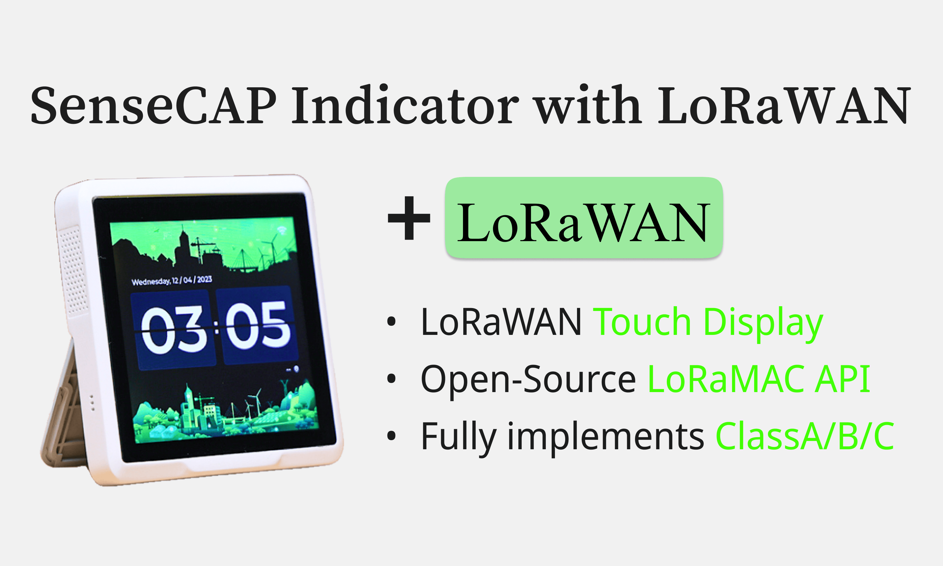
LoRaWAN End Node - SenseCAP Indicator
Hands-On Demo
In this section, we'll delve into the SenseCAP Indicator's basic LoRaWAN(Class C & OTAA) functionality through a practical demonstration. The process is divided into three main steps:
- Obtain Firmware: Customize and install the firmware as needed.
- Registering the Device: Add your device to a LoRaWAN Network Server.
- Configuring LoRaWAN Credentials: Enter necessary network details on your SenseCAP Indicator.
Before we begin, let's get some background on LoRaWAN.
LoRaWAN
LoRaWAN is described as a Low Power, Wide Area (LPWA) networking protocol that wirelessly connects battery-operated devices to the internet across large regions or networks. It's a part of the LoRa wireless system and operates in a license-free spectrum, supporting long-range communication with limited bandwidth. It is characterized by long-range communication (up to 10 miles), long battery life (up to 10 years), low cost, and low power usage with a payload size ranging from 51 to 241 bytes depending on the data1.
Advanced Perception System
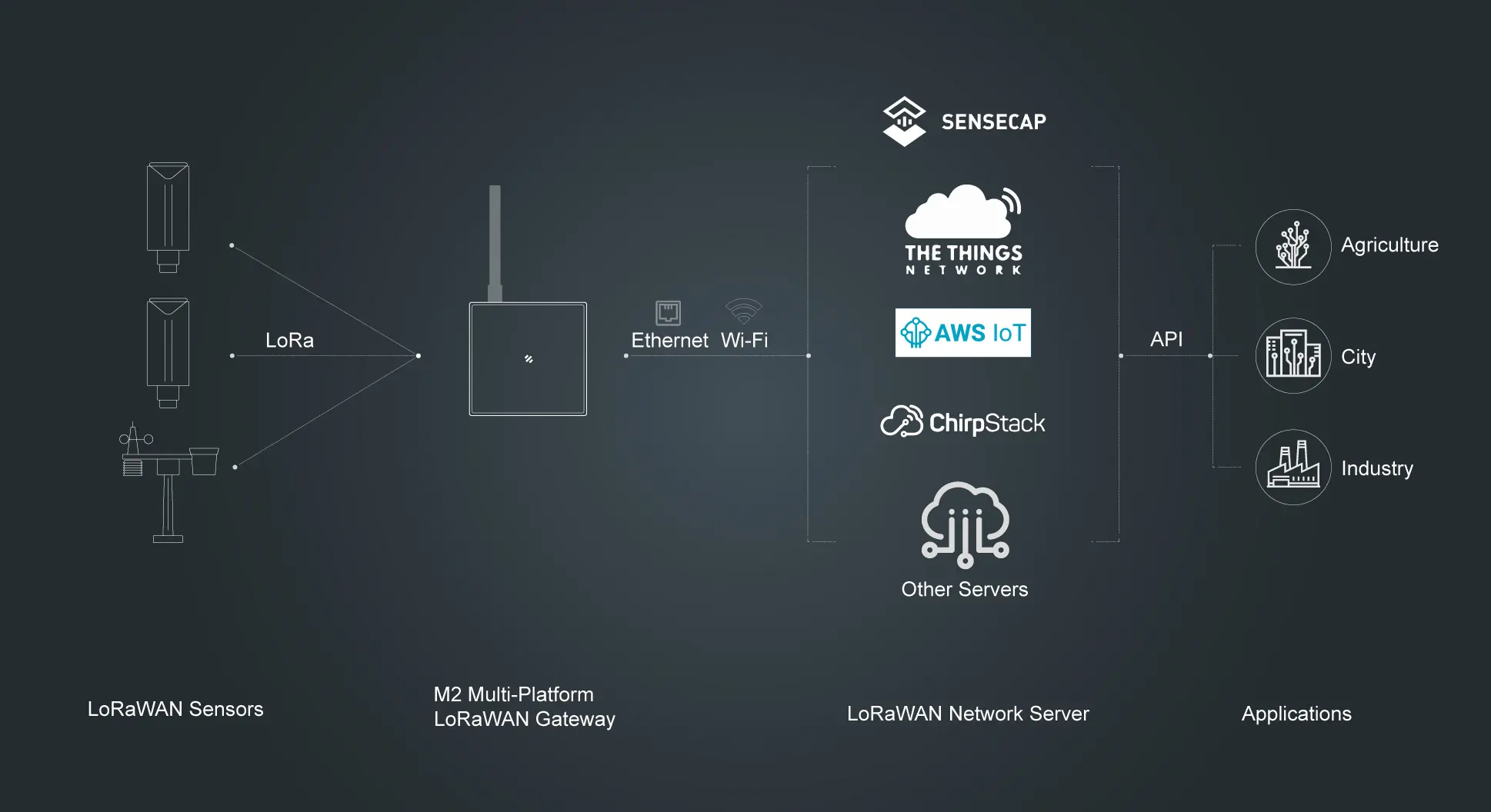
Seeed Studio's "Advanced Perception System" is an IoT solution that provides a comprehensive array of sensing, networking, edge computing tools and cloud designed to enhance environmental awareness across various industries. This system, equipped with a diverse array of modules and devices2, acts as the digital "eyes and ears," facilitating a transformative understanding of the real world.
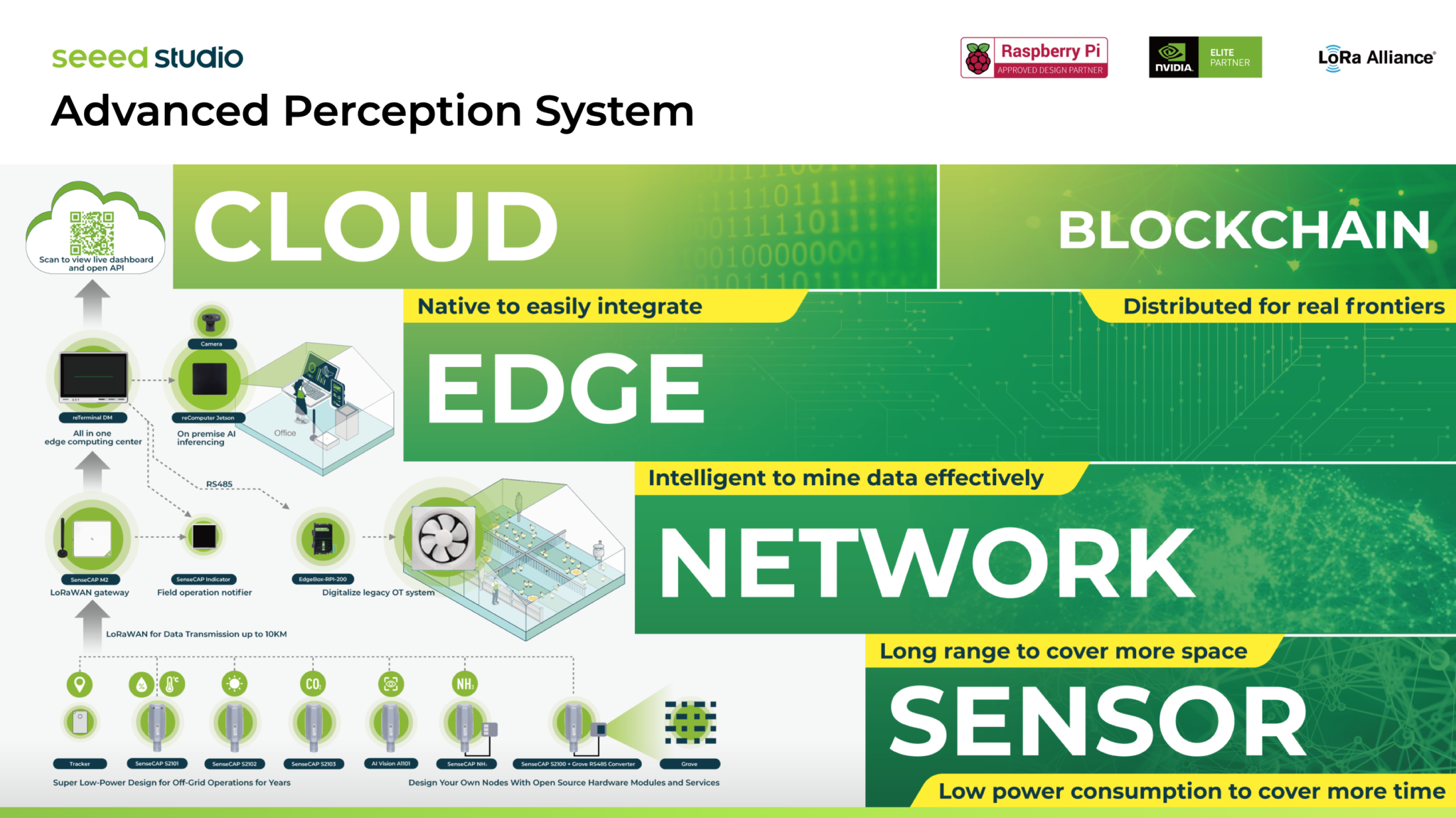
The SenseCAP Team focuses primarily on Sensor and Network components, committing to delivering top-notch quality and bespoke industry solutions. Their work has resulted in the creation of acclaimed offerings, such as the innovative Smart Village Solution, which has garnered praise for its practicality and forward-thinking design.
In the realm of the Helium network, the team's contributions are particularly noteworthy. Devices like the SenseCAP M1, M2, and M4 are not just high-performance Helium hotspots; they are pivotal in enabling users to earn HNT cryptocurrency while concurrently constructing a decentralized wireless LoRaWAN® network infrastructure. The SenseCAP M4 Square stands out for its ability to operate multiple Web 3.0 Apps, thereby streamlining the deployment of intricate multi-application systems.3
Leveraging this profound expertise and continual engagement with a diverse customer base, the SenseCAP Team has strategically decided to integrate LoRa functionality into the SenseCAP Indicator.
Let's take a closer look at the SenseCAP Indicator's LoRaWAN functionality.
Overview
| Feature | Details |
|---|---|
| Radio Transceivers | SX1262 |
| Classes Supported | Class A/B/C |
| Supported Frequency Bands | AS923, AU915, CN779, EU433, EU868, KR920, IN865, US915, RU864, US915 |
| LoRaWAN Mac Version | 1.0.4/1.1.0 |
| End-device LoRaWAN Stack Adopted | LoRaMac-node |
| Documentation | LoRaMac Documentation |
Step 1. Obtain Firmware
1.1 Download Firmware
To begin, download the LoRaWAN firmware, indicator_lorawan.bin, for the SenseCAP Indicator from the GitHub Release page.
The ESP-IDF Programming Guide(v5.1) provides insights on building your own. You can access and modify the source code to suit your specific needs.
1.2 Flash Firmware
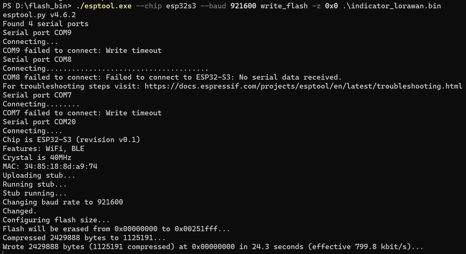
To flash the firmware onto the SenseCAP Indicator, download it first and then use esptool (or esptool.py if you have an ESP-IDF environment) to flash it(for comprehensive guidance, refer to the instructions).
Flashing firmware on Windows using esptool:
Use the command below in the Windows command prompt to flash the firmware:
<tool_path>/esptool.exe --chip esp32s3 --baud 921600 write_flash -z 0x0 <firmware_path>/indicator_lorawan.bin
For example, if your flash_bin folder is located in drive D: and contains the following structure:
flash_bin/
├── esptool.exe
└── indicator_lorawan.bin
Your command will look like this:
./esptool.exe --chip esp32s3 --baud 921600 write_flash -z 0x0 ./indicator_lorawan.bin
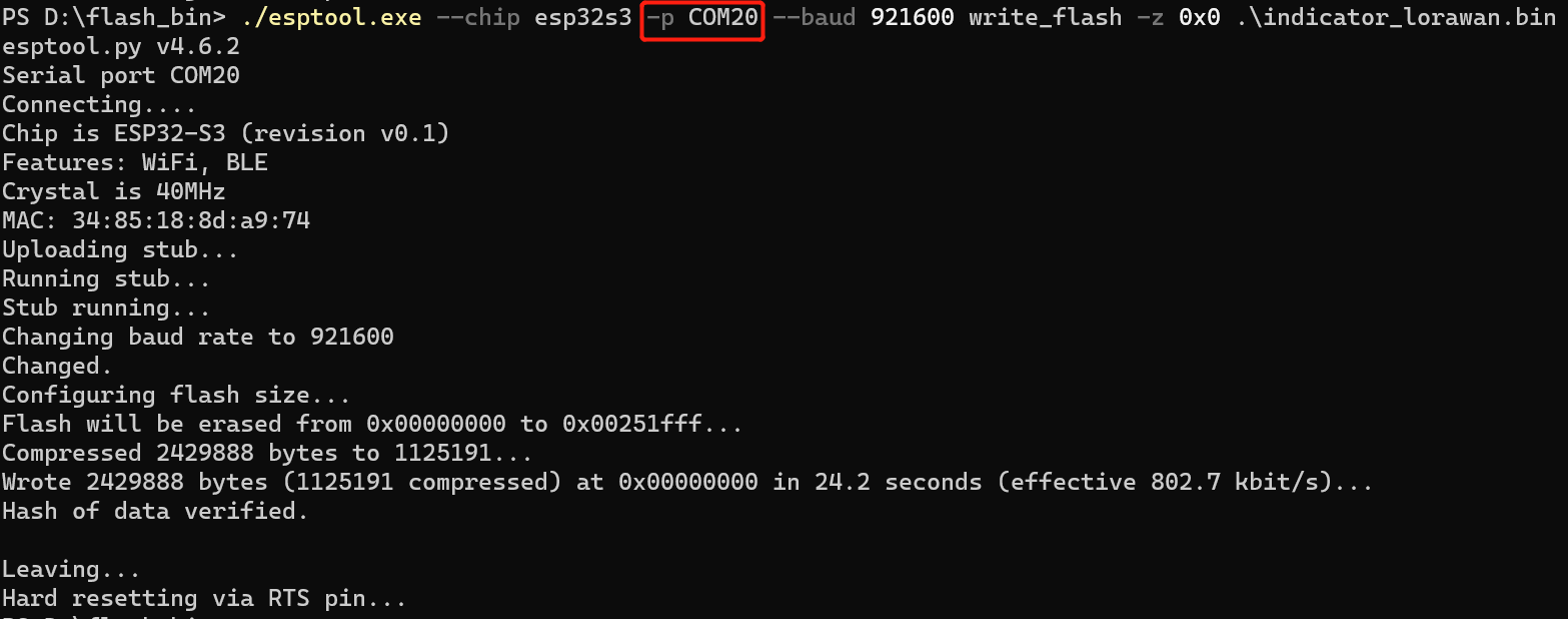
If you have multiple ports and need to specify one, use the -p or --port argument:
./esptool.exe --chip esp32s3 -p COM20 --baud 921600 write_flash -z 0x0 ./indicator_lorawan.bin
Mac users should replace ./esptool.exe with ./esptool.
If you encounter issues during flashing, consider reducing the baud speed or refer to these troubleshooting steps.
Once the firmware is successfully flashed, retrieve essential parameters like the Device EUI and APPkey from the LoRaWAN Network Server from the subsequent steps.
Step 2. Register the Device on LoRaWAN Network Server
Before starting, ensure your device is within a LoRaWAN network's coverage area.
This section will guide you through connecting to a local LoRaWAN network server. We will use the ChirpStack platform as an example, alongside the SenseCAP M2 Multi-Platform LoRaWAN Indoor Gateway (EU868). If you are employing a different network server, the procedure will be similar; you'll need to collect the essential information for activation:
- OTAA (Over The Air Activation):
- DevEUI
- AppKey
- JoinEUI/AppEUI (Mac Version 1.1.0 needed)
- ABP (Activation By Personalization):
- DevEUI
- DevAddr
- AppSKey
- NwkSKey
2.1 Configure the SenseCAP LoRaWAN Gateway
To configure your SenseCAP gateway, access its web interface where you'll begin setting up a ChirpStack network server. Below is a visual guide displaying the configuration page:
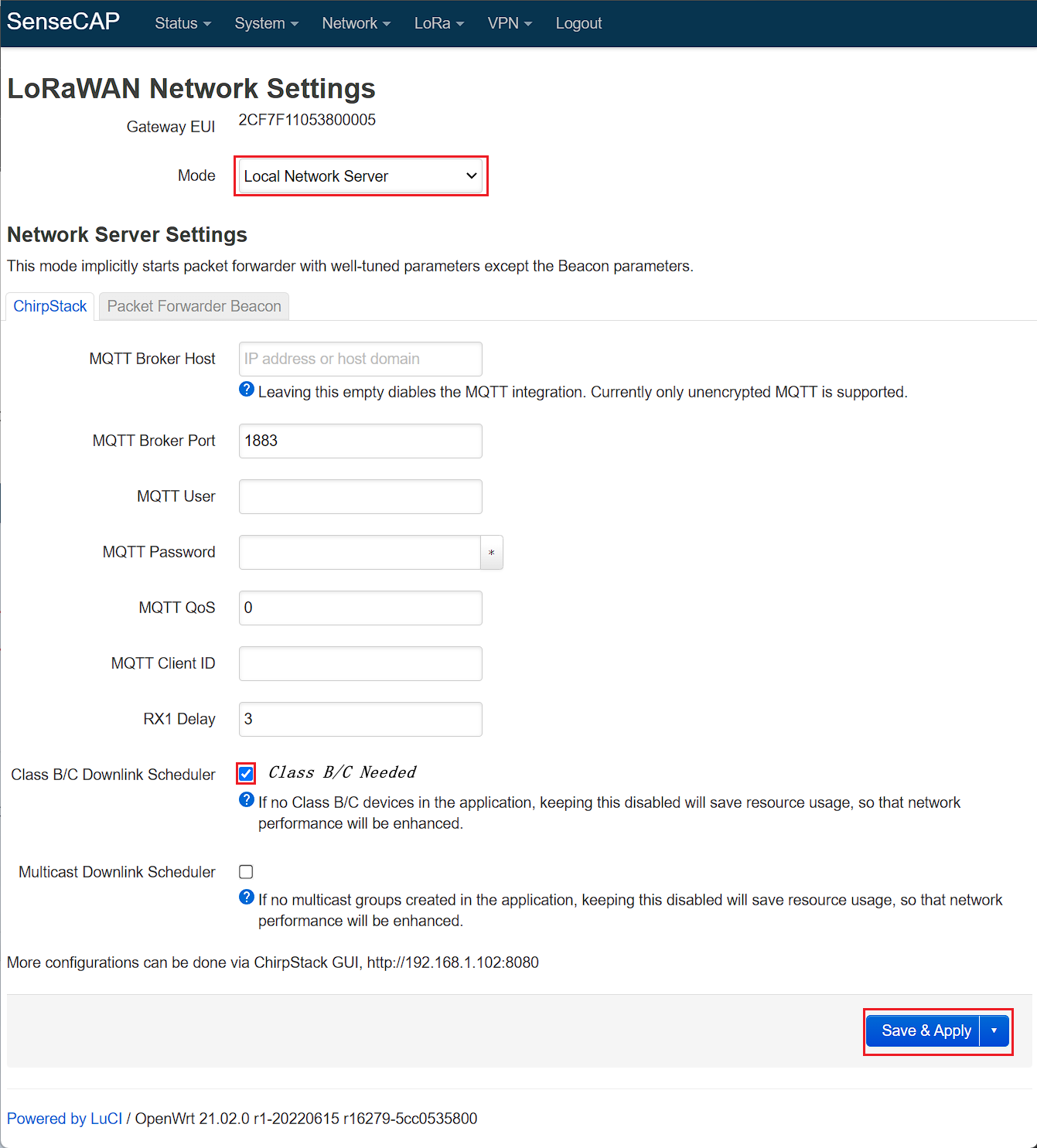
After adjusting the settings, click Save & Apply to commit your changes. You can then access the ChirpStack interface using the provided URL (for example, http://192.168.1.102:8080).
Use the following default credentials to log in:
- Username:
admin - Password:
admin
For further details and advanced configuration options, visit the SenseCAP M2 Gateway LNS Configuration Guide.
2.2 Configure the Local Network Server (ChirpStack)
Refer to the ChirpStack documentation for detailed features and LoRaWAN version support: ChirpStack Network Server Documentation.
Here are the steps to configure your local network server using ChirpStack:
- Create a Device Profile: This standardizes the settings and capabilities of your devices. It's crucial for ensuring that your devices communicate effectively within the network.
- Add an Application: This helps organize and manage your devices. Applications are used to group devices that share the same purpose or characteristics, making management more straightforward.
- Register a device under an application: This step links your device to the specific settings and data handling rules you've established in your application. It's a critical step to make sure your device operates correctly within your network.
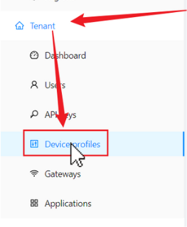
2.2.1 Create a Device Profile
To create a new device profile in Device profiles, go to 'Tenant' in the sidebar and then select 'Device profiles'.
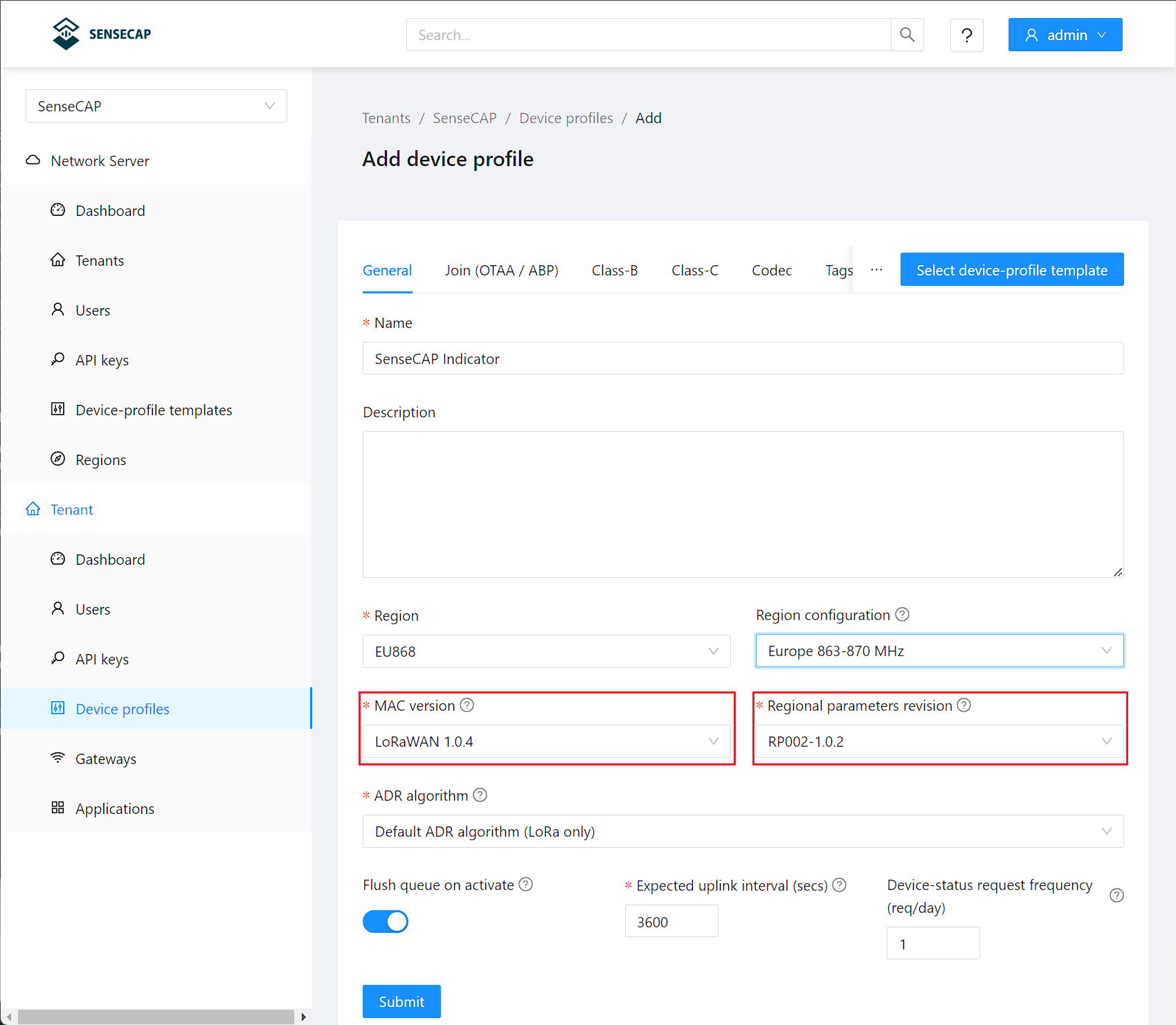
Creating a device profile is a crucial step in ensuring your device effectively communicates over the LoRaWAN network. This involves selecting technical parameters that influence the device's performance and compatibility. Here's how you can set it up:
- MAC Version: This refers to the version of the Media Access Control (MAC) protocol your device utilizes. The MAC protocol is essential for managing how your device accesses the network. You can select between versions v1.0.4 and v1.1.0.
- Regional Parameters Revision: These are the specific parameters that need to be configured based on the geographical location of your device. They ensure that the device complies with local regulations and network specifications.
Choosing MAC Version
The MAC version you select is pivotal as it determines the set of credentials your device will require:
- MAC Version 1.0.4
- MAC Version 1.1.0
You'll need the following credentials:
- DevEUI: This is a unique identifier assigned to your device, ensuring global uniqueness.
- AppKey: A secret key used for encrypting and securing your device's communications.
Your device will require these credentials:
- DevEUI: A globally unique identifier for your device.
- AppEUI/JoinEUI: A unique identifier for the application your device connects to.
- AppKey: The cryptographic key used for securing communications.
Choosing Regional Parameters Revision
In the context of setting up a device profile for the LoRaWAN network, the Regional Parameters (RP) version you choose is crucial for ensuring your device operates in compliance with specific regional standards and specifications.
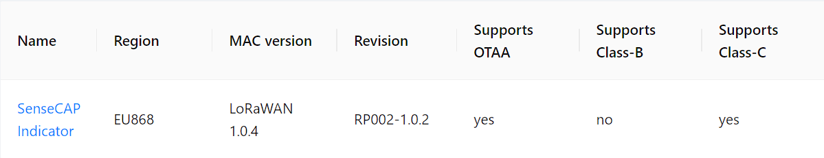
Current Setup
For now, we are setting up a device profile with MAC Version 1.0.4 and Regional Parameters Revision RP002-1.0.2.
For configuring a device profile on the LoRaWAN network, RP002-1.0.2 is a suitable choice for current needs. RP002-1.0.3 is recommended by the code as per the v4.7.0 LoRaMac-node specification.
Correctly understanding and configuring the necessary elements is key to ensuring your device communicates effectively and securely over the LoRaWAN network.
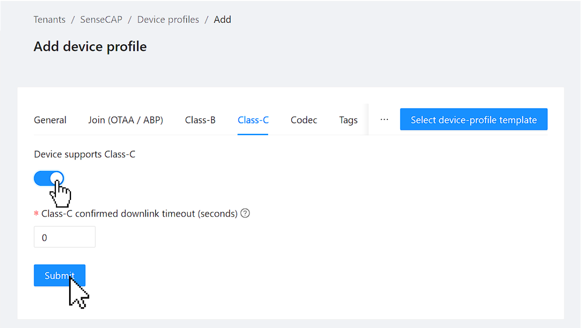
To use Class C device type, it's important to specifically enable this functionality in your device profile.
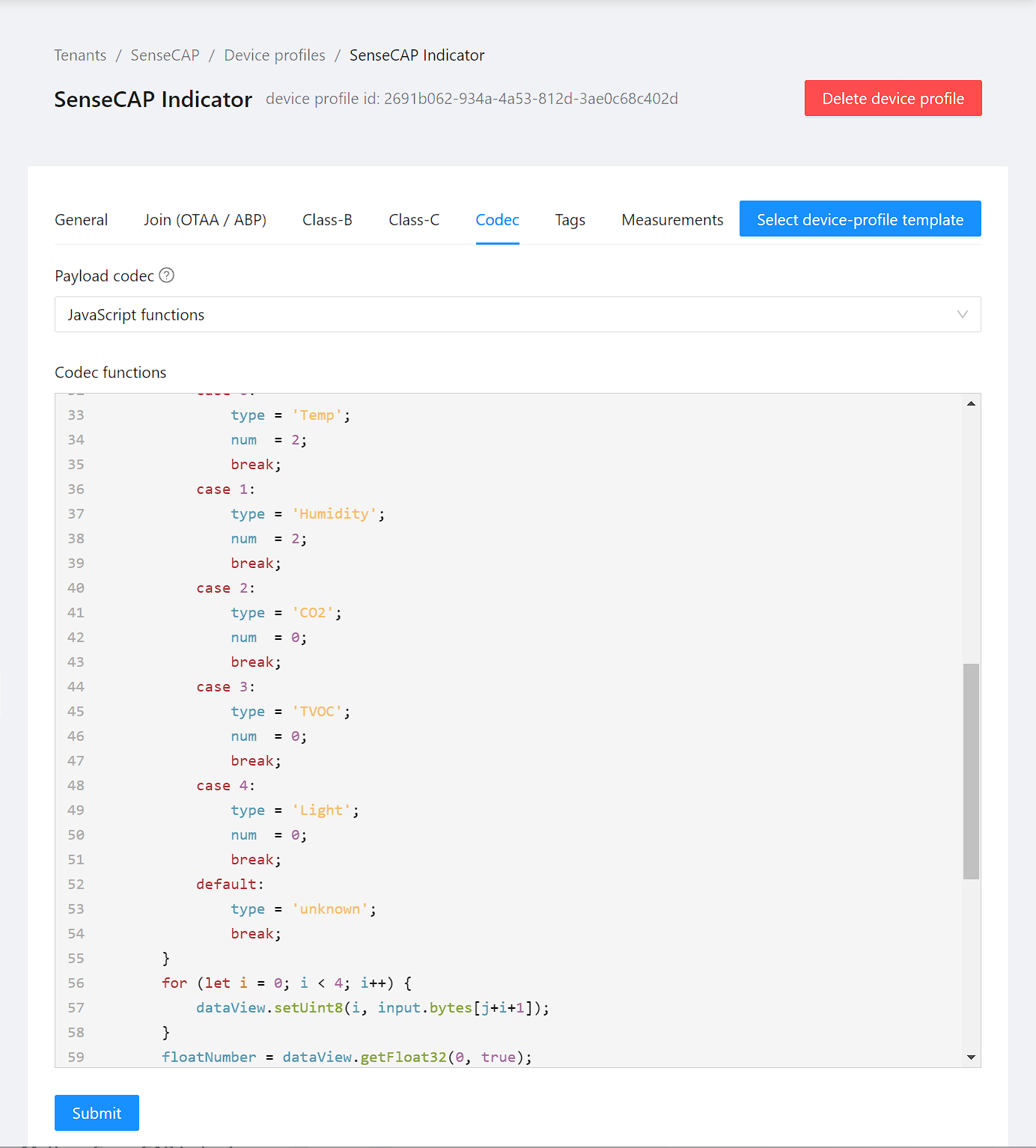
Decoder Function
Indeed, to make the payload data transmitted by your device meaningful and interpretable, it's essential to implement a decoder within the device profile. This decoder will translate the raw binary data into a readable format, allowing you to understand and utilize the information your device sends effectively.
Click to copy Decoder.js
The docoder is from GitHub repository
function decodeUplink(input) {
    var decoded = {
        data:[]
    };
    var type;
    var floatNumber;

    if ( (input.bytes.length  % 5) !== 0) {
        decoded.data.push({
            type: "error",
            Value: -1
        });

        return { data: decoded }
    }

    const arrayBuffer = new ArrayBuffer(4);
    const dataView = new DataView(arrayBuffer);

    for(let j =0 ; j < input.bytes.length; j+=5) {
        var num =0;
        switch ( input.bytes[j]) {
            case 0:
                type = 'Temp';
                num  = 2;
                break;
            case 1:
                type = 'Humidity';
                num  = 2;
                break;
            case 2:
                type = 'CO2';
                num  = 0;
                break;
            case 3:
                type = 'TVOC';
                num  = 0;
                break;
            case 4:
                type = 'Light';
                num  = 0;
                break;
            default:
                type = 'unknown';
                break;
        }
        for (let i = 0; i < 4; i++) {
            dataView.setUint8(i, input.bytes[j+i+1]);
        }
        floatNumber = dataView.getFloat32(0, true);
        decoded.data.push({
            type:  type,
            Value: floatNumber.toFixed(num)
        });
    }
    return { data: decoded }
}

function encodeDownlink(input) {
  return {
    bytes: [225, 230, 255, 0]
  };
}
Once device profile is created, the next step is to add an application.
2.2.2 Add an Application
Create and configure an application within your LoRaWAN Network Server to manage your devices.
To create a new Application, go to 'Tenant' in the sidebar and then select 'Application'.
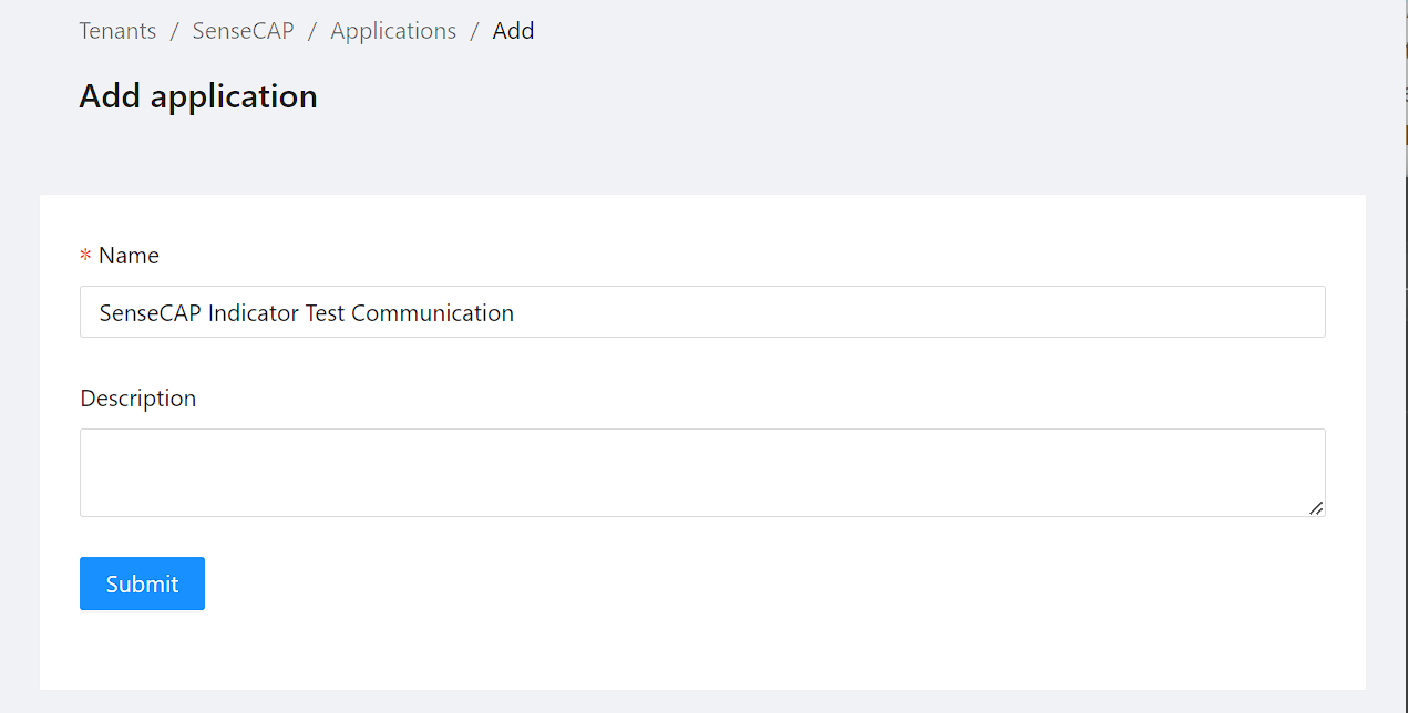
To submit, set the Name and optionally provide a description.
2.2.3 Register a device under an application
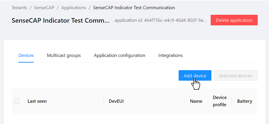
Press the Add device button in your application.
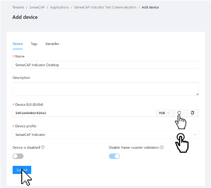
To add a device, you need to specify a Name and provide a Device EUI along with the Device Profile you've previously created.
You can opt to auto-generate the Device EUI or use an existing one from your device.
For this process, we'll employ the auto-generated Device EUI. After submitting these details, the device will be added to the application, and you'll be automatically redirected to the OTAA Keys section.
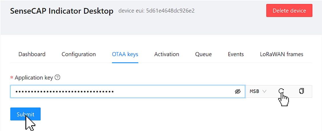
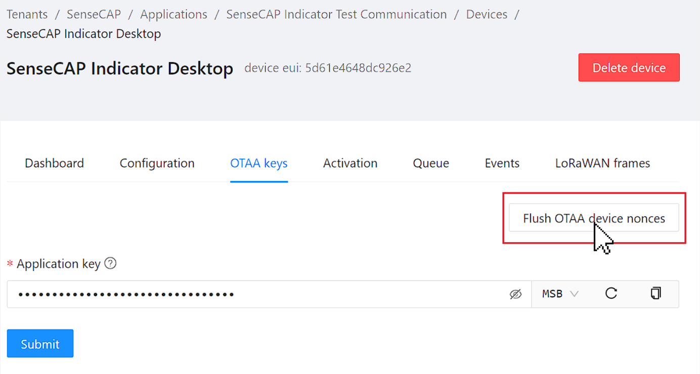
Click the button to generate a random Application Key (AppKey) or opt to use a pre-existing one. Ensure you have all the necessary credentials and parameters. For MAC Version 1.0.4, the required credentials are:
- DevEUI (Example):
5d61e4648dc926e2 - AppKey (Example):
ec2b966c2c4bbe94a6ef79d0479db0e5
With these details, we have the command:
lorawan --eui 5d61e4648dc926e2 --app_key ec2b966c2c4bbe94a6ef79d0479db0e5
For additional commands and assistance, refer to the console command section.
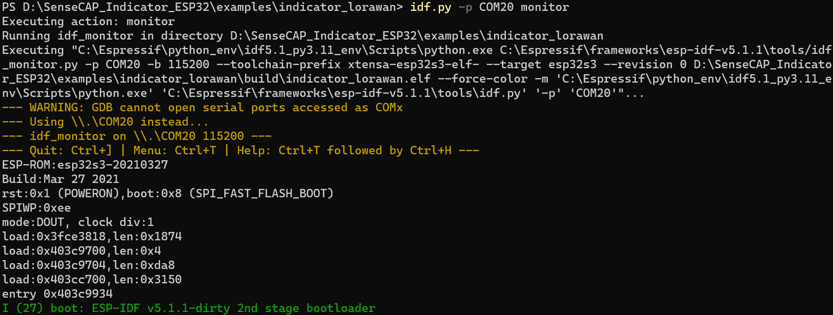
Step 3. Configure SenseCAP Indicator to Join Network
To establish a connection with your SenseCAP Indicator, you can use any serial tool(Minicom, Putty, etc.) or just use idf monitor(follow the detailed instructions provided in the ESP-IDF documentation):
Ensure your device hasn't started the LoRaWAN connection before this step. If it has, you'll need to stop it.
Enter the commands including the credentials in the console.
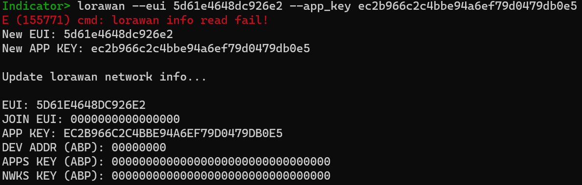
Now, you should be able to view the keys on your SenseCAP Indicator. If necessary, make any required updates to the configurations.
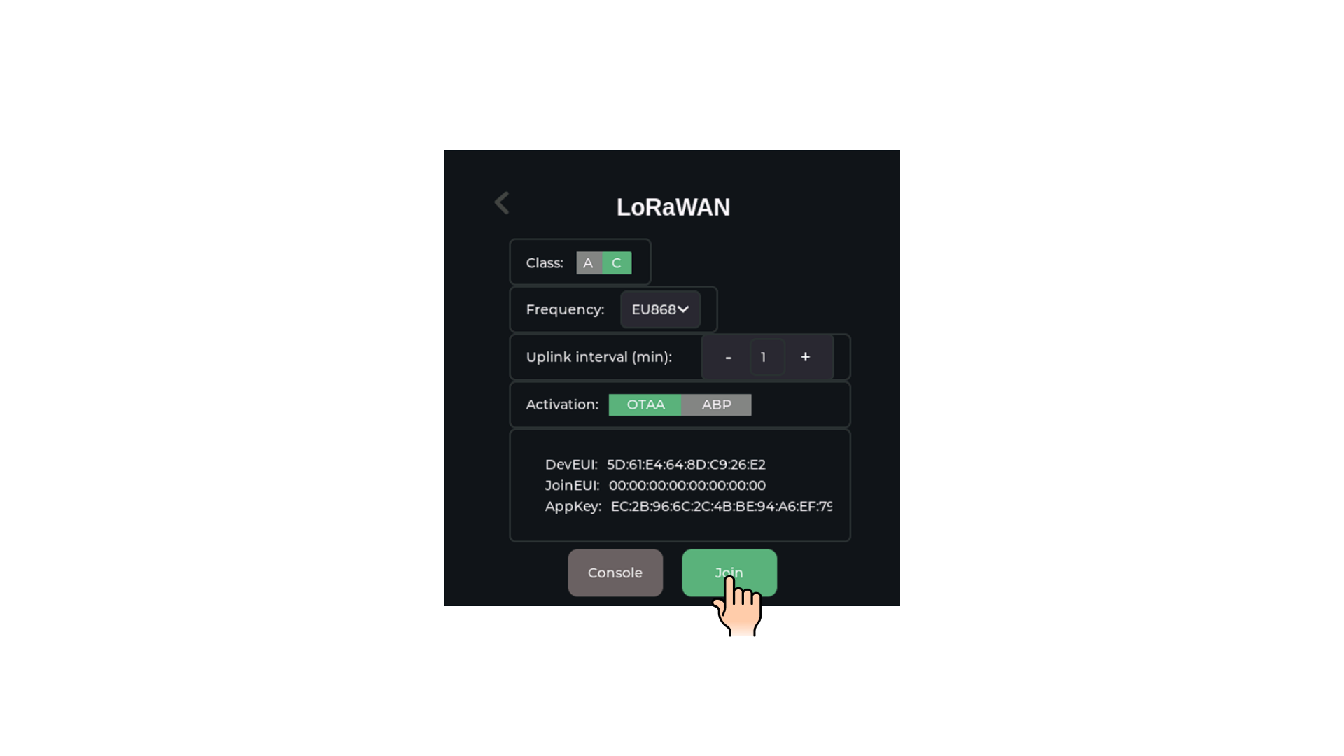
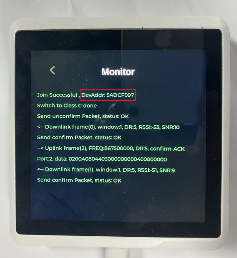
When you pressed the Join button, you'll be able to observe the connection process directly through the console, allowing you to monitor and verify the successful establishment of the connection.
Step 4 Sending and Receiving Messages
In this section, we will walk you through the process of monitoring both uplink and downlink communications between your device and the LoRaWAN network.4
Uplink Message
Uplink messages are fundamental in a LoRaWAN network, enabling devices like the SenseCAP Indicator to transmit data to a network server. These messages are crucial for reporting sensor data, device status, and other telemetry information.
The Concept of Uplink Message
Uplink in LoRaWAN:
In a LoRaWAN network, an uplink message is any communication initiated by an end device (like the SenseCAP Indicator) and sent to the network server through a gateway. These messages are typically used for transmitting sensor readings or device status.
-
Data Collection: The SenseCAP Indicator collects data from its sensors or internal processes. This could include environmental readings, device status, or other relevant metrics.
-
Data Packaging: The collected data is then packaged into a predefined format suitable for transmission. This may involve encoding the data to optimize payload size and ensure efficient transmission.
-
Sending the Message: The device transmits the uplink message through the LoRaWAN network. This transmission is usually scheduled based on specific intervals (e.g., every 5 minutes) or triggered by certain events (e.g., a threshold breach).
Receiving and Processing at the Network Server:
Once the uplink message is sent by the SenseCAP Indicator, it is received by the LoRaWAN network server via a gateway. The network server then processes the message as follows:
-
Message Reception: The network server receives the uplink message from the gateway and decodes it.
-
Data Processing and Analysis: After decoding, the server processes the data, which might involve logging it, triggering alerts, or performing further analysis. The data can include various types of information such as temperature readings, humidity levels, or other sensor data, depending on the capabilities of the device.
-
Response Actions: Based on the received data, the network server may take action, such as sending a downlink message to the device with instructions or updates. This response can be automated based on predefined rules or triggered manually by a user monitoring the system.
Uplink Message: upload Sensor Data
In the context of the LoRaWAN demo using the SenseCAP Indicator, the uplink message might consist of simple sensor data, like temperature or humidity readings.
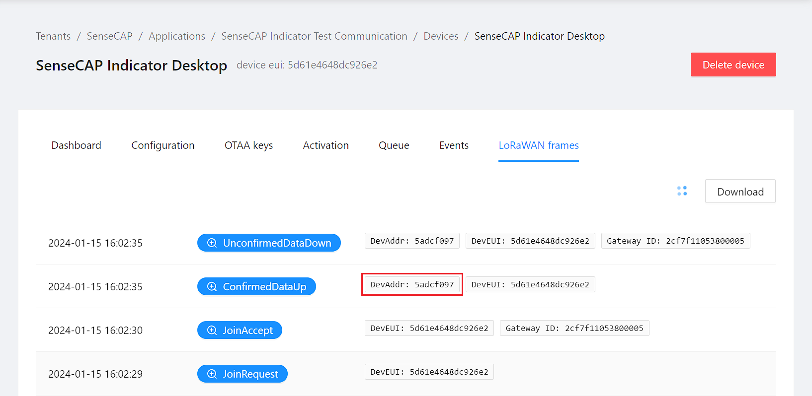
Once the join process is successful, you can view the logs in the LoRaWAN frames section to monitor the data transmission and receive a detailed account of the device's communication with the network.
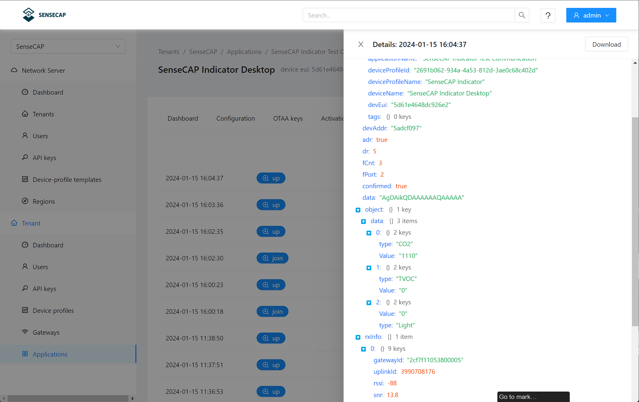
Navigate to the LoRaWAN frames section of a device within the application you've created, and locate your specific device. This is where you can monitor and manage the data packets being transmitted and received by your device, ensuring smooth communication and operation within the LoRaWAN network.
Now, with the decoder function activated, you should be able to see the parsed data under the event section (you can reveal this by pressing the +up button). This will allow you to understand and analyze the incoming data from your device more effectively.
Downlink Message
The downlink process in the LoRaWAN network is critical for bi-directional communication, allowing the transmission of data and commands from the network server back to the SenseCAP Indicator device. This capability is particularly useful for various operational commands, configuration changes, or firmware updates.
The Concept of Downlink Message
Downlink in LoRaWAN:
In the LoRaWAN demo environment, downlink messages are used to control an animated bulb on the SenseCAP Indicator, allowing users to switch it on or off. However, this functionality can be extended to execute specific commands or configurations as needed.
Sending a Downlink Message
-
Initiating a Downlink Message: To send a downlink message, you will typically use the network server’s interface. Navigate to the section where you can schedule downlink messages for your device.
-
Message Format: Ensure that the message is formatted according to the specifications required by the SenseCAP Indicator. This could include specific payload formats or encoding methods, depending on what the downlink message is intended to do.
-
Scheduling the Message: After composing the message, schedule it to be sent at an appropriate time. The timing may depend on various factors, such as the device’s data transmission schedule or its expected time of activity.
Receiving and Processing the Downlink Message on the Device
Once a downlink message is transmitted by the LoRaWAN network server, the SenseCAP Indicator will receive it during its next receive window. The device processes the message as follows:
-
Message Reception: The SenseCAP Indicator listens for downlink messages during predefined receive windows. It is crucial that the device is in a receptive state during these periods.
-
Processing the Message: Upon receiving a downlink message, the device will process the contents. This could involve changing a setting, updating a parameter, or triggering an action like toggling a relay or adjusting a sensor threshold5.
- Feedback and Confirmation: If the downlink message requires confirmation (in case of a confirmed downlink), the device will send an acknowledgment in its next uplink message.
Demo Message: Controlling a Bulb
In this demonstration, we'll illustrate how downlink messages can be used to control a simulated bulb on the Indicator within via the LoRaWAN network. This example showcases the practical application of downlink communication for remote device management.
1. Scenario Overview:
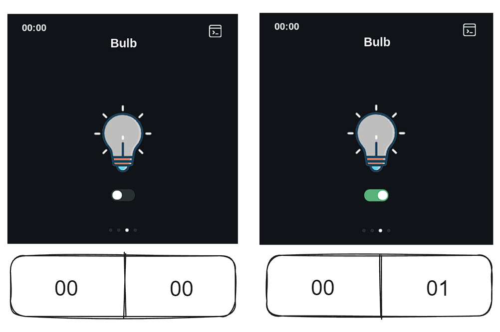
- In this demo, the SenseCAP Indicator is configured with a virtual bulb, which represents a simple, controllable device.
- The bulb has two states: 'on' and 'off', which are controlled via downlink messages sent from the LoRaWAN network server.
2. Preparing the Downlink Message:
-
To control the bulb, a specific payload structure is defined for the downlink message. For simplicity, let's assume:
- Sending the payload
0001turns the bulb on. - Sending the payload
0000turns the bulb off.
- Sending the payload
-
These payloads are encoded in a format that the SenseCAP Indicator is programmed to understand and act upon.6
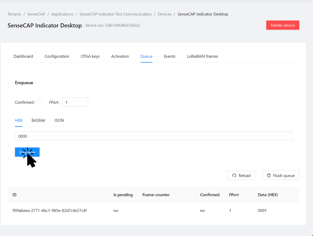
3. Sending the Downlink Message:
- Through the network server's interface, you can schedule the downlink message with the corresponding payload.
- The message is then queued and sent to the SenseCAP Indicator during its next available receive window(so there is delay).
4. Receiving the Downlink Message:
For turning the bulb on, you schedule a downlink with payload 0001. To turn it off, you use payload 0000. As I had enqueued a downlink message 0001, now I want to send a downlink message 0000 to turn the bulb off.
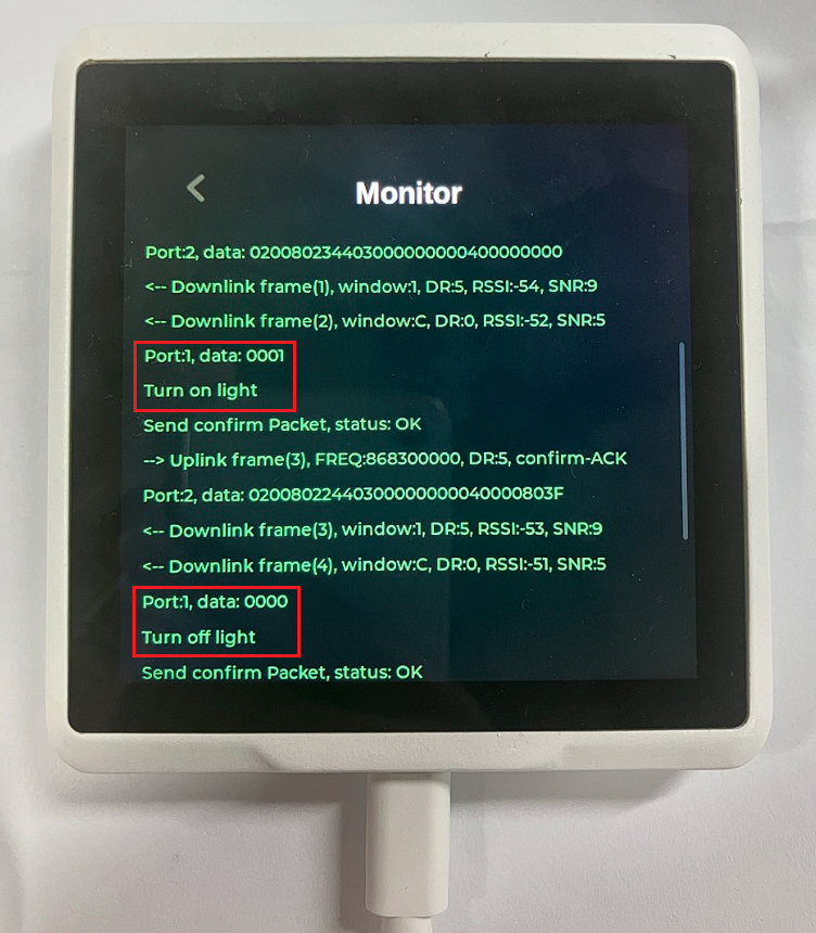
And you can see that the bulb is turned off.
Funtionalities wait to be explored
There's a wide array of functionalities in the SenseCAP Indicator waiting to be explored. In this demo, we illustrate uploading sensor data and using downlink messages to control the SenseCAP Indicator's virtual bulb.
Key Capabilities to Explore:
1. Command Reception and Execution:
- The SenseCAP Indicator efficiently receives downlink messages.
- It processes these messages, interpreting commands like turning the virtual bulb on or off.
- The bulb's state changes accordingly, offering a realistic simulation of device control.
2. Confirmation and Verification:
- Following command execution, the SenseCAP Indicator sends back an uplink message as confirmation.
- This acknowledgment can be tracked via the
network server's interface, ensuring the command was effectively received and acted upon.
3. Practical Applications:
- This simple demo underscores the utility of LoRaWAN downlink messages in manipulating IoT devices.
- It showcases a key aspect of IoT ecosystems: the ability to remotely direct and manage devices, demonstrating its practical value.
This demonstration is just the beginning. The SenseCAP Indicator offers a versatile platform for various IoT applications, from environmental monitoring to smart automation. By delving deeper into its capabilities, you can unlock the full potential of this powerful tool, paving the way for innovative solutions and enhanced control in your IoT projects. We encourage you to experiment and discover the many ways the SenseCAP Indicator can enhance your IoT endeavors.
Console Manual Page
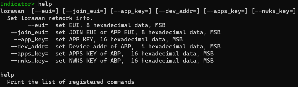
Here's an introduction to the terminal command for setting up LoRaWAN network information, styled like a manual entry:
lorawan
This command configures the LoRaWAN network information for a device. It allows you to set various parameters required for both OTAA (Over-the-Air Activation) and ABP (Activation By Personalization) methods.
Usage
lorawan [--eui=] [--join_eui=] [--app_key=] [--dev_addr=] [--apps_key=] [--nwks_key=]
Options
-
--eui=: Sets the EUI (Extended Unique Identifier) for the device. It requires 8 hexadecimal digits, with MSB (Most Significant Bit) first. -
--join_eui=: Sets the JOIN EUI (formerly known as APP EUI) which is an application identifier in OTAA. It requires 8 hexadecimal digits, with MSB first. -
--app_key=: Sets the APP KEY, which is a cryptographic key used in the OTAA joining process. It requires 16 hexadecimal digits, with MSB first. -
--dev_addr=: Sets the Device Address for ABP. It's a 4 hexadecimal digit identifier, with MSB first. -
--apps_key=: Sets the APPS KEY for ABP, which is used for encrypting application payloads. It requires 16 hexadecimal digits, with MSB first. -
--nwks_key=: Sets the NWKS KEY for ABP, which is used for encrypting network payloads and for device authentication. It requires 16 hexadecimal digits, with MSB first.
FAQs
Can the SenseCAP Indicator serve as my LoRaWAN Gateway?
No, the SenseCAP Indicator is not designed to function as a LoRaWAN Gateway according to the SX1262 lora transceiver. It is primarily an end device in the LoRaWAN network architecture. A LoRaWAN Gateway typically has different hardware and software capabilities, designed to connect multiple end devices like the SenseCAP Indicator to the network server. If you're looking for a LoRaWAN Gateway, you should consider devices specifically designed for this purpose.
Why is the True Network Server not sending a joinAccept?
Note: There are a few scenarios where a device may fail to receive a joinAccept from the network server:
-
Frequency Change: If you alter the frequency settings but retain the same device credentials on the network server, the device may not synchronize properly.
-
Device Flash Cleaned: If you've cleared the device's flash memory but continue using the same credentials, this can lead to synchronization issues.
In both cases, it's crucial to ensure that the OTAA (Over-the-Air Activation) device nonces (number used once) are in sync. To address this, use the Flush OTAA device nonces feature on your network server. This action will reset the nonces and help re-establish a proper connection.
Which FPort to send downlink message?
In the current setup of our LoRaWAN demo, there isn't a pre-defined port designated for sending downlink messages. The demo code is designed to be flexible and can be adapted to your specific needs.
If you require the processing of messages on a specific port in a particular manner, you have the option to modify the code accordingly. This customization allows for tailored handling of downlink messages based on different ports, giving you greater control over how your device interprets and responds to these communications.
How to Use MAC Version 1.1.0?
To utilize the features of LoRaWAN MAC version 1.1.0, it's necessary to configure the cryptographic settings appropriately. You can do this by using the idf.py menuconfig command to enable the USE LRWAN_1_1_X_CRYPTO option.
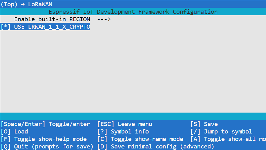
The implementation of version 1.1.0 in LoRaWAN requires specific cryptographic algorithms for enhanced security. By setting this option, you ensure that your device is compatible with the enhanced security features and protocols introduced in this version.
ODM Service
Seeed Studio offers a comprehensive one-stop ODM service to accommodate rapid customizations and scaling requirements for diverse needs. If you're looking to tailor your project with specialized features or need assistance in scaling up your operations efficiently, please reach out to us. For inquiries and more detailed information, contact us at [email protected]. We're here to help turn your unique ideas into reality.
Tech Support
Need help with your SenseCAP Indicator? We're here to assist you!
If you encounter any issues or have any questions while following this tutorial, please feel free to reach out to our tech support. We are always here to help!
Visit our Seeed Official Discord Channel to ask your questions or the GitHub discussions to share all you want!