使用 Seeed Studio XIAO ESP32-S3(Sense)进行引脚复用
| Seeed Studio XIAO ESP32-S3 | Seeed Studio XIAO ESP32-S3 Sense | Seeed Studio XIAO ESP32-S3 Plus |
|---|---|---|
 |  |  |
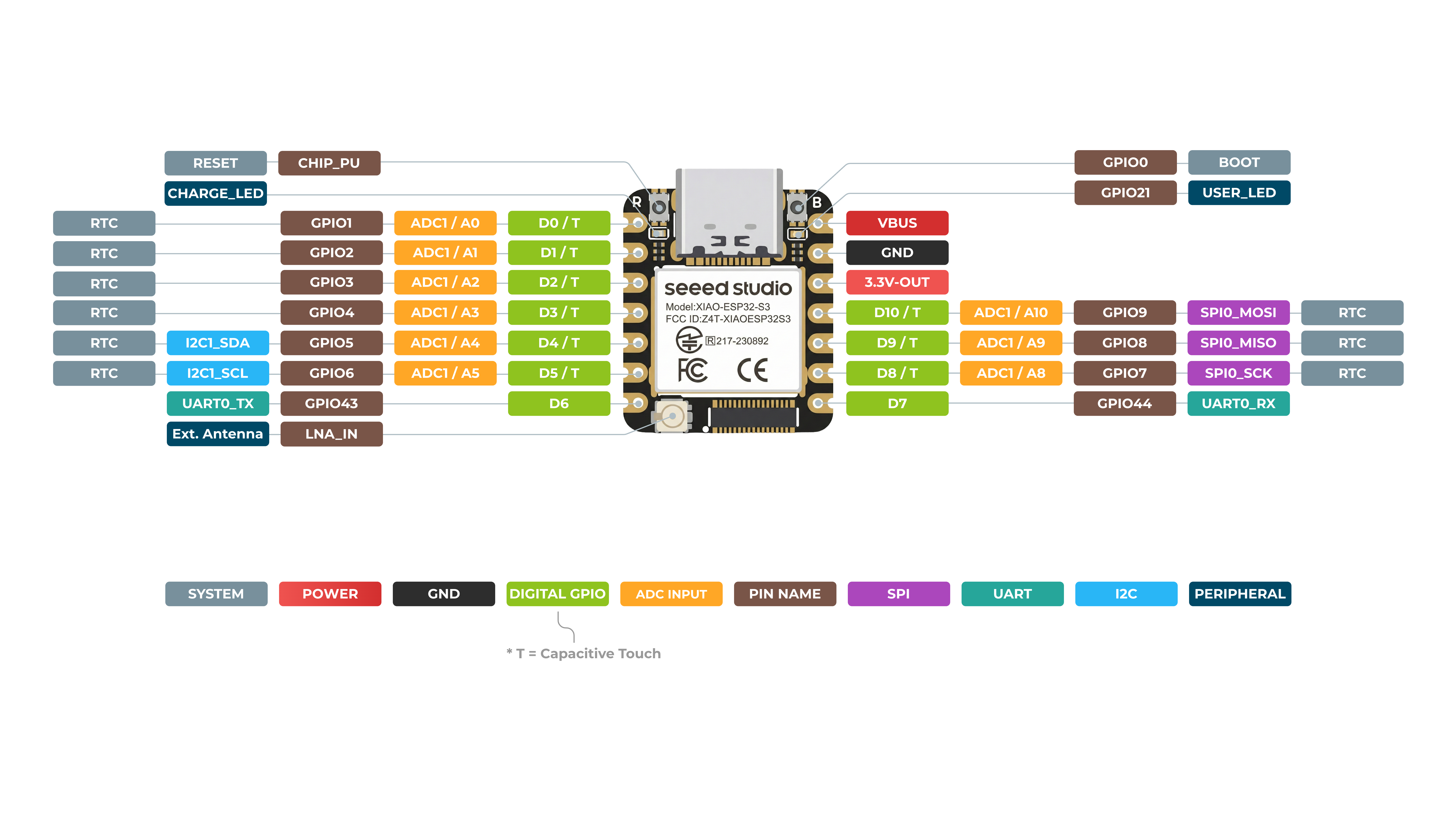
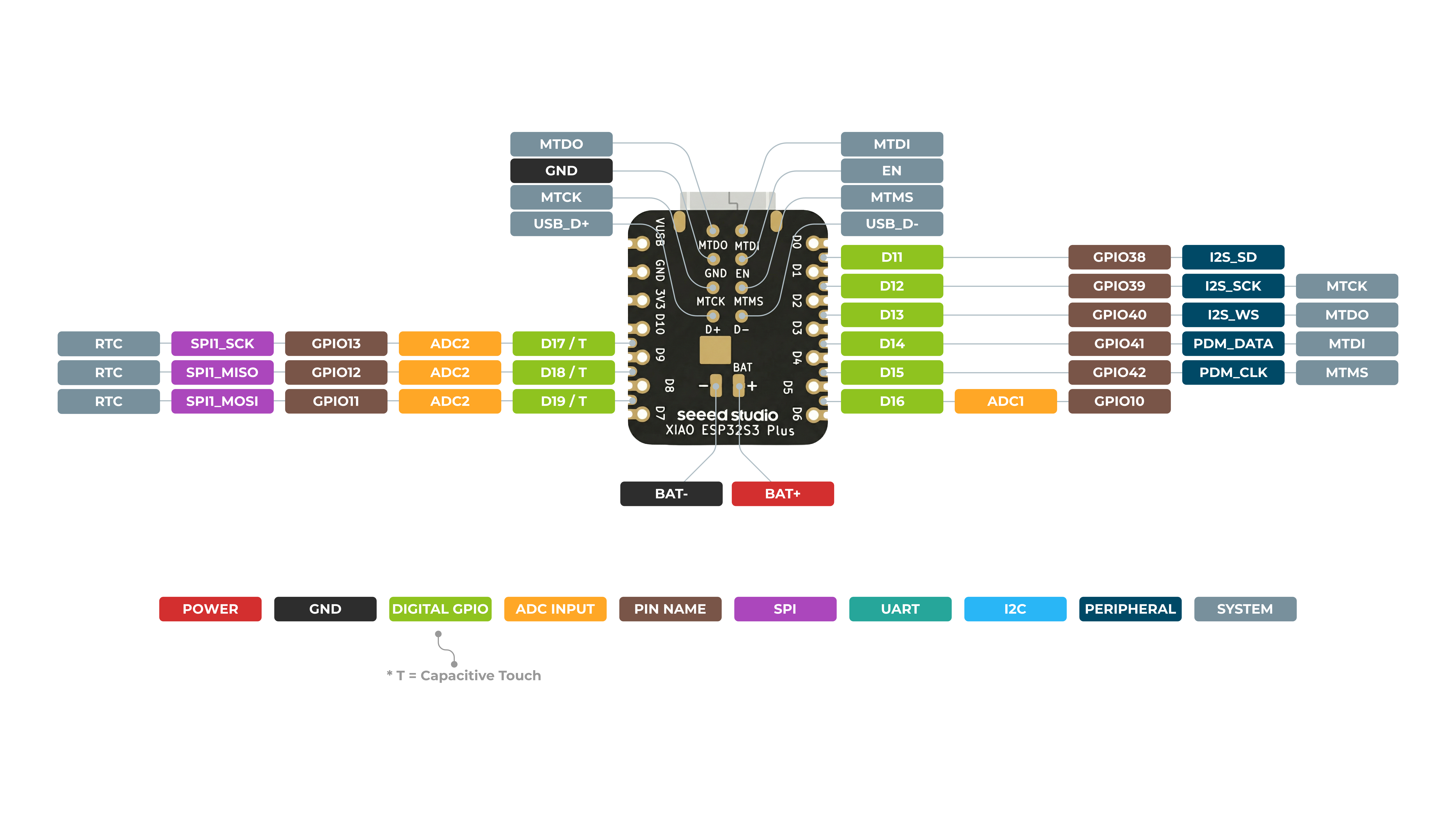
Seeed Studio XIAO ESP32-S3 是一款功能强大且多用途的开发板,具有多种外设接口和 GPIO 引脚。这些引脚可用于多种用途,例如与其他设备通信、读取模拟传感器、控制 LED 等。在本教程中,我们将通过以下原理图来探索 XIAO ESP32-S3 及其相关板卡 XIAO ESP32-S3 Sense 的引脚分布,并学习如何将这些引脚用于不同的用途。具体来说,我们将介绍 1 路 UART、1 路 IIC、1 路 IIS、1 路 SPI、11 路 GPIO(PWM)、9 路 ADC、1 个用户 LED、1 个充电 LED、1 个复位按钮、1 个 Boot 按钮,以及对于 XIAO ESP32-S3 Sense,1 个 B2B 连接器(带 2 个额外 GPIO)。在完成本教程后,你将对 XIAO ESP32-S3 的引脚分布有良好的理解,并能够在你的项目中高效地使用它。
入门指南
引脚概览
在开始之前,让我们先通过下图原理图回顾一下 XIAO ESP32-S3 拥有的所有引脚及其功能。
硬件概述
在一切开始之前,了解一些产品的基本参数是非常重要的。下表提供了有关 Seeed Studio XIAO ESP32-S3 特性的相关信息。
- XIAO ESP32-S3
- XIAO ESP32-S3 Sense
- XIAO ESP32-S3 Plus
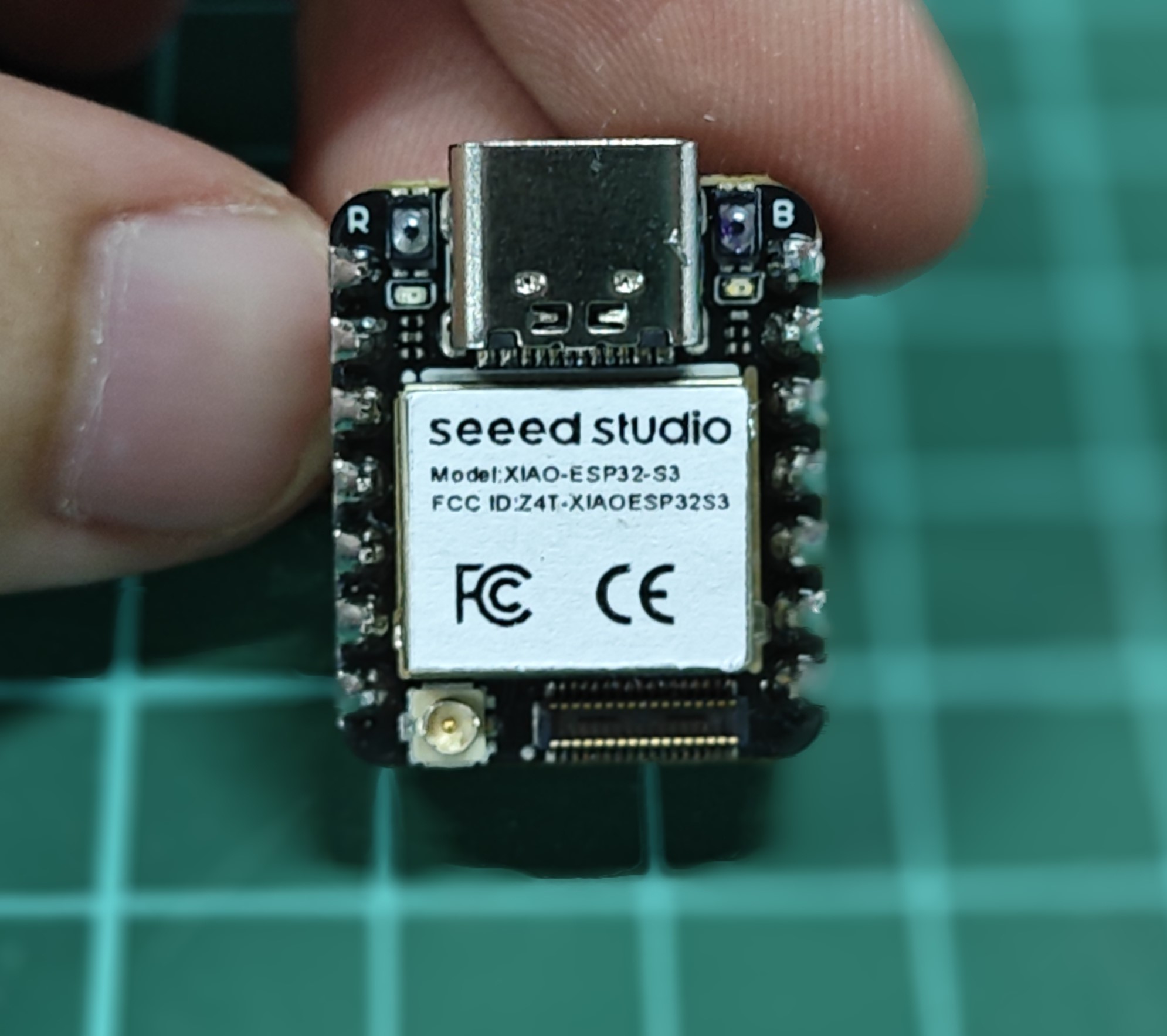
XIAO ESP32-S3 正面
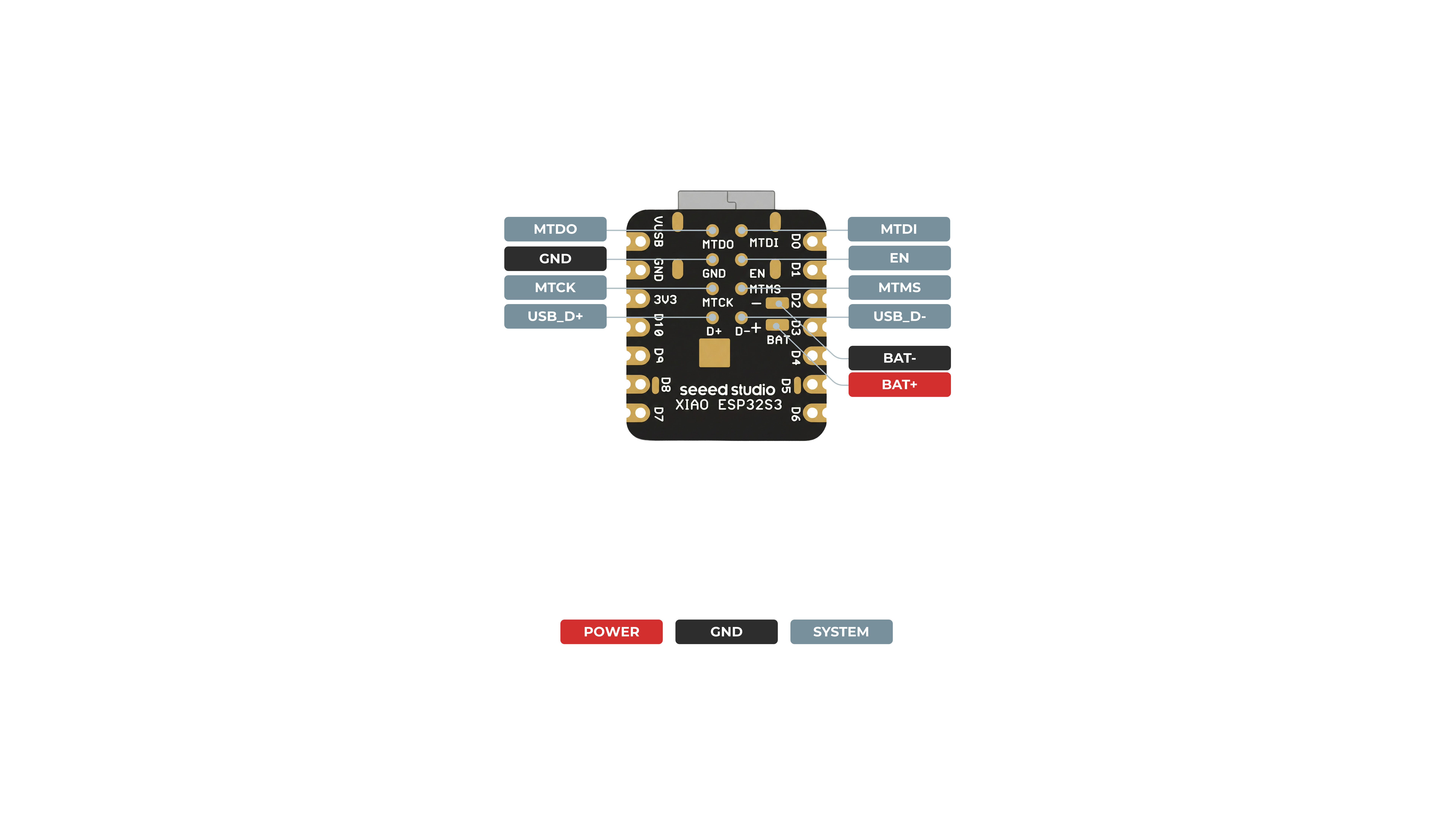
XIAO ESP32-S3 背面
引脚映射
| XIAO 引脚 | 功能 | 芯片引脚 | 复用功能 | 描述 |
|---|---|---|---|---|
| 5V | VBUS | 电源输入/输出 | ||
| GND | ||||
| 3V3 | 3V3_OUT | 电源输出 | ||
| D0 | 模拟 | GPIO1 | TOUCH1 | GPIO,ADC |
| D1 | 模拟 | GPIO2 | TOUCH2 | GPIO,ADC |
| D2 | 模拟 | GPIO3 | TOUCH3 | GPIO,ADC |
| D3 | 模拟 | GPIO4 | TOUCH4 | GPIO,ADC |
| D4 | 模拟,SDA | GPIO5 | TOUCH5 | GPIO,I2C 数据,ADC |
| D5 | 模拟,SCL | GPIO6 | TOUCH6 | GPIO,I2C 时钟,ADC |
| D6 | TX | GPIO43 | GPIO,UART 发送 | |
| D7 | RX | GPIO44 | GPIO,UART 接收 | |
| D8 | 模拟,SCK | GPIO7 | TOUCH7 | GPIO,SPI 时钟,ADC |
| D9 | 模拟,MISO | GPIO8 | TOUCH8 | GPIO,SPI 数据,ADC |
| D10 | 模拟,MOSI | GPIO9 | TOUCH9 | GPIO,SPI 数据,ADC |
| D11 | 模拟 | GPIO42 | TOUCH12 | GPIO,ADC |
| D12 | 模拟 | GPIO41 | TOUCH13 | GPIO,ADC |
| MTDO | GPIO40 | JTAG | ||
| MTDI | GPIO41 | JTAG,ADC | ||
| MTCK | GPIO39 | JTAG,ADC | ||
| MTMS | GPIO42 | JTAG,ADC | ||
| Reset | CHIP_PU | |||
| Boot | GPIO0 | 进入 Boot 模式 | ||
| U.FL-R-SMT1 | LNA_IN | UFL 天线 | ||
| CHARGE_LED | 充电指示灯 | |||
| USER_LED | GPIO21 | 用户指示灯 |
XIAO ESP32-S3 Sense 正面
XIAO ESP32-S3 Sense 背面

引脚映射
| XIAO 引脚 | 功能 | 芯片引脚 | 复用功能 | 描述 |
|---|---|---|---|---|
| 5V | VBUS | 电源输入/输出 | ||
| GND | ||||
| 3V3 | 3V3_OUT | 电源输出 | ||
| D0 | 模拟 | GPIO1 | TOUCH1 | GPIO,ADC |
| D1 | 模拟 | GPIO2 | TOUCH2 | GPIO,ADC |
| D2 | 模拟 | GPIO3 | TOUCH3 | GPIO,ADC |
| D3 | 模拟 | GPIO4 | TOUCH4 | GPIO,ADC |
| D4 | 模拟,SDA | GPIO5 | TOUCH5 | GPIO,I2C 数据,ADC |
| D5 | 模拟,SCL | GPIO6 | TOUCH6 | GPIO,I2C 时钟,ADC |
| D6 | TX | GPIO43 | GPIO,UART 发送 | |
| D7 | RX | GPIO44 | GPIO,UART 接收 | |
| D8 | 模拟,SCK | GPIO7 | TOUCH7 | GPIO,SPI 时钟,ADC |
| D9 | 模拟,MISO | GPIO8 | TOUCH8 | GPIO,SPI 数据,ADC |
| D10 | 模拟,MOSI | GPIO9 | TOUCH9 | GPIO,SPI 数据,ADC |
| D11 | 模拟 | GPIO42 | TOUCH12 | GPIO,ADC |
| D12 | 模拟 | GPIO41 | TOUCH13 | GPIO,ADC |
| MTDO | GPIO40 | JTAG | ||
| MTDI | GPIO41 | JTAG,ADC | ||
| MTCK | GPIO39 | JTAG,ADC | ||
| MTMS | GPIO42 | JTAG,ADC | ||
| Reset | CHIP_PU | |||
| Boot | GPIO0 | 进入 Boot 模式 | ||
| U.FL-R-SMT1 | LNA_IN | UFL 天线 | ||
| CHARGE_LED | 充电指示灯 | |||
| USER_LED | GPIO21 | 用户指示灯 | ||
| Digital microphone_CLK | GPIO42 | MIC 的 PDM 时钟引脚 | ||
| Digital microphone_DATA | GPIO41 | MIC 的 PDM 数据引脚 | ||
| Onboard SD Card__CS | GPIO3 | 板载 SD 卡片选引脚 | ||
| Onboard SD Card_SCK | GPIO7 | 板载 SD 卡时钟引脚 | ||
| Onboard SD Card_MISO | GPIO8 | 板载 SD 卡数据输入引脚 | ||
| Onboard SD Card Slot_MOSI | GPIO9 | 板载 SD 卡数据输出引脚 |
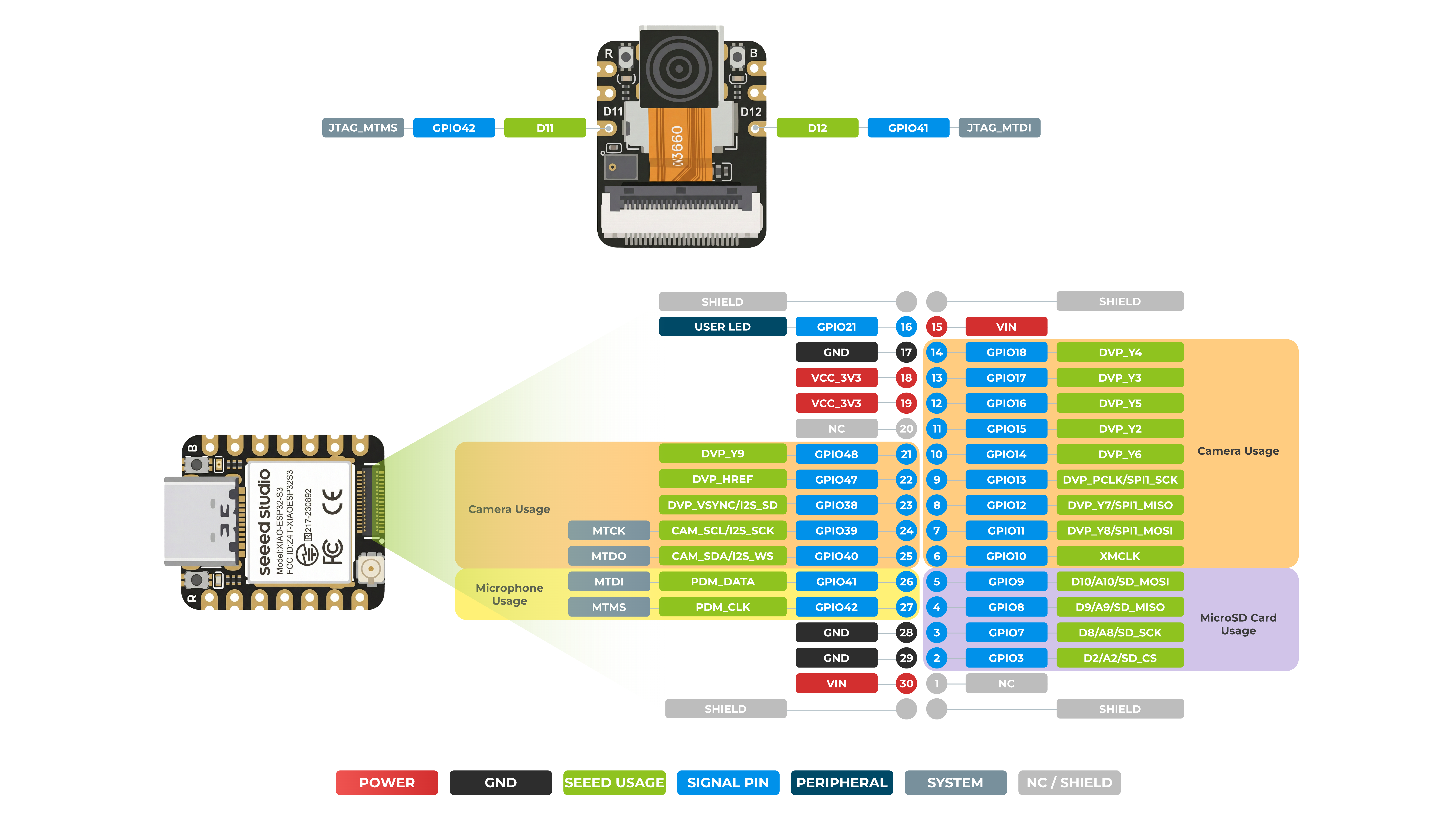
摄像头
| 芯片引脚 | 描述 |
|---|---|
| GPIO10 | 摄像头相关时钟引脚 |
| GPIO11 | 摄像头视频数据引脚 (Y8) |
| GPIO12 | 摄像头视频数据引脚 (Y7) |
| GPIO13 | 摄像头像素时钟引脚 |
| GPIO14 | 摄像头视频数据引脚 (Y6) |
| GPIO15 | 摄像头视频数据引脚 (Y2) |
| GPIO16 | 摄像头视频数据引脚 (Y5) |
| GPIO17 | 摄像头视频数据引脚 (Y3) |
| GPIO18 | 摄像头视频数据引脚 (Y4) |
| GPIO40 | 摄像头 I2C 数据引脚 |
| GPIO39 | 摄像头 I2C 时钟引脚 |
| GPIO38 | 摄像头垂直同步引脚 |
| GPIO47 | 摄像头水平同步引脚 |
| GPIO48 | 摄像头视频数据引脚 (Y9) |
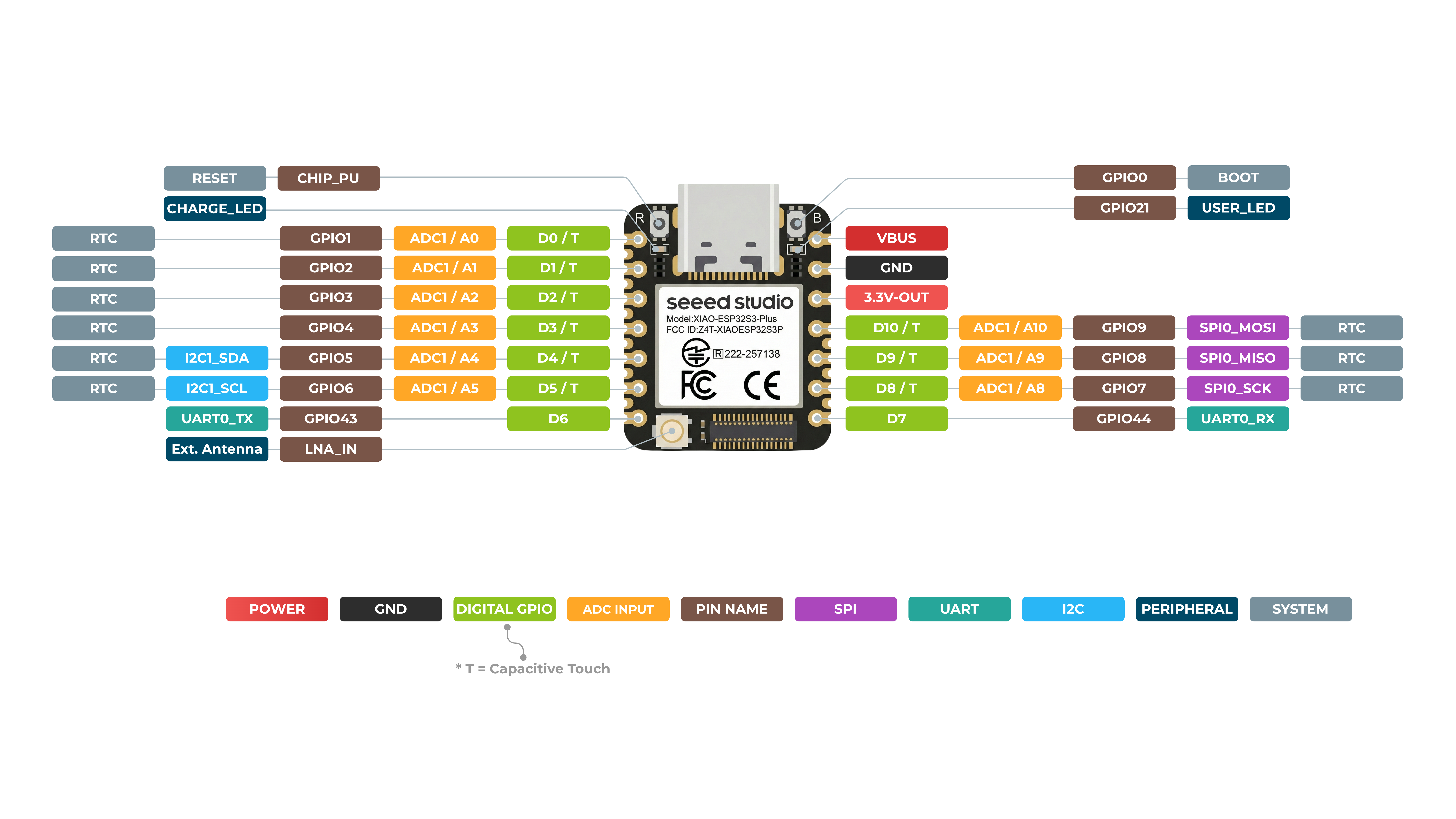
XIAO ESP32-S3 Plus 正面
XIAO ESP32-S3 Plus 背面
引脚映射
| XIAO 引脚 | 功能 | 芯片引脚 | 复用功能 | 描述 |
|---|---|---|---|---|
| 5V | VBUS | 电源输入/输出 | ||
| GND | ||||
| 3V3 | 3V3_OUT | 电源输出 | ||
| D0 | 模拟 | GPIO1 | GPIO,ADC | |
| D1 | 模拟 | GPIO2 | GPIO,ADC | |
| D2 | 模拟 | GPIO3 | GPIO,ADC | |
| D3 | 模拟 | GPIO4 | GPIO,ADC | |
| D4 | 模拟,SDA | GPIO5 | GPIO,I2C 数据,ADC | |
| D5 | 模拟,SCL | GPIO6 | GPIO,I2C 时钟,ADC | |
| D6 | TX | GPIO43 | GPIO,UART 发送 | |
| D7 | RX | GPIO44 | GPIO,UART 接收 | |
| D8 | 模拟,SCK | GPIO7 | GPIO,SPI 时钟,ADC | |
| D9 | 模拟,MISO | GPIO8 | GPIO,SPI 数据,ADC | |
| D10 | 模拟,MOSI | GPIO9 | GPIO,SPI 数据,ADC | |
| D11 | GPIO38 | GPIO,ADC | ||
| D12 | GPIO39 | GPIO,ADC | ||
| D13 | GPIO40 | |||
| D14 | GPIO41 | |||
| D15 | GPIO42 | |||
| D16 | GPIO10 | |||
| D17 | GPIO13 | |||
| D18 | GPIO12 | |||
| D19 | GPIO11 | |||
| MTDO | GPIO40 | JTAG | ||
| MTDI | GPIO41 | JTAG,ADC | ||
| MTCK | GPIO39 | JTAG,ADC | ||
| MTMS | GPIO42 | JTAG,ADC | ||
| Reset | CHIP_PU | |||
| Boot | GPIO0 | 进入 Boot 模式 | ||
| ADC_BAT | GPIO10 | 读取电池电压值 | ||
| U.FL-R-SMT1 | LNA_IN | UFL 天线 | ||
| CHARGE_LED | VCC_3V3 | CHG-LED | ||
| USER_LED | GPIO21 | 用户指示灯 |
-
尽管 XIAO ESP32-S3 将 GPIO41 和 GPIO42 分配给 A11 和 A12 引脚,但由于 ESP32-S3 芯片本身的特性,A11 和 A12 引脚不支持 ADC 功能。请务必加以区分和辨别。
-
XIAO ESP32-S3 Plus 的 B2B 连接器兼容 Wio-SX1262 extension board,但不兼容插拔式摄像头传感器板。
-
5V - 这是来自 USB 接口的 5V 输出。你也可以将其用作电压输入,但必须在外部电源和该引脚之间串联某种二极管(肖特基、信号或功率二极管),二极管的阳极接电池,阴极接 5V 引脚。
-
3V3 - 这是板载稳压器的稳压输出。你最多可以从中汲取 700mA 电流
-
GND - 电源/数据/信号地
下面是 XIAO ESP32-S3 功能引脚的概览。
| 引脚编号 | 功能描述 |
|---|---|
| -- PDM 麦克风引脚 -- | |
| GPIO 41 | PDM 麦克风 DATA |
| GPIO 42 | PDM 麦克风 CLK |
| -- MicroSD 卡 SPI 引脚 -- | |
| GPIO 21 | MicroSD SPI CS |
| D8 / A8 / Qt7 / GPIO7 | MicroSD SPI SCK |
| D9 / A9 / Qt8 / GPIO8 | MicroSD SPI MISO |
| D10 / A10 / Qt9 / GPIO9 | MicroSD SPI MOSI |
| -- 摄像头引脚 -- | |
| GPIO 10 | XMCLK |
| GPIO 11 | DVP_Y8 |
| GPIO 12 | DVP_Y7 |
| GPIO 13 | DVP_PCLK |
| GPIO 14 | DVP_Y6 |
| GPIO 15 | DVP_Y2 |
| GPIO 16 | DVP_Y5 |
| GPIO 17 | DVP_Y3 |
| GPIO 18 | DVP_Y4 |
| GPIO 38 | DVP_VSYNC |
| GPIO 39 | 摄像头 SCL |
| GPIO 40 | 摄像头 SDA |
| GPIO 47 | DVP_HREF |
| GPIO 48 | DVP_Y9 |
焊接排针
为了按照本教程使用各个引脚的功能,我们建议你事先将排针焊接好。
由于 XIAO ESP32-S3 体积非常小,焊接排针时请务必小心,不要将不同引脚焊接在一起,也不要让焊锡粘到屏蔽罩或其他元件上。否则可能导致 XIAO 短路或无法正常工作,由此造成的后果将由用户自行承担。
如果你选择了 Sense 版本,恭喜你!你将拥有两个额外的 GPIO 引脚。如果计划使用它们,可以单独在这两个引脚上焊接排针。
数字
XIAO ESP32-S3 最多具有 11 个常规 GPIO 引脚和 9 个模拟引脚。在本示例中,我们将使用 XIAO ESP32-S3、XIAO 扩展板和一个继电器来演示如何使用不同的数字引脚进行读写。
硬件准备
| Seeed Studio XIAO ESP32-S3 | Seeed Studio XIAO ESP32-S3 Sense | Seeed Studio Expansion Base for XIAO with Grove OLED | Grove - Relay |
|---|---|---|---|
| |  |  |
请将 XIAO ESP32-S3 或 Sense 安装到扩展板上,并通过 Grove 线缆将继电器连接到扩展板的 A0/D0 接口。最后,通过 USB-C 线缆将 XIAO 连接到电脑。
软件实现
在本示例中,我们将通过连接到 XIAO 扩展板的按键来实现对继电器开关状态的控制。按下按键时,继电器打开;松开按键时,继电器关闭。
const int buttonPin = D1;     // the number of the pushbutton pin
int buttonState = 0;          // variable for reading the pushbutton status
const int relayPin = D0;

void setup() {
  // initialize the Relay pin as an output:
  pinMode(relayPin, OUTPUT);
  // initialize the pushbutton pin as an input:
  pinMode(buttonPin, INPUT_PULLUP);
}

void loop() {
  // read the state of the pushbutton value:
  buttonState = digitalRead(buttonPin);

  // check if the pushbutton is pressed. If it is, the buttonState is HIGH:
  if (buttonState == HIGH) {
    // turn Relay on:
    digitalWrite(relayPin, HIGH);
  } else {
    // turn Relay off:
    digitalWrite(relayPin, LOW);
  }
}
如果一切顺利,在上传程序后,你应该会看到如下效果。
如果你想使用数字功能,那么你应该使用字母 "D" 作为引脚编号的前缀,例如 D4、D5。相反,如果你想使用引脚的模拟功能,则应该使用字母 "A" 作为引脚编号的前缀,例如 A4、A5。
适用于 Sense 版本
对于 XIAO ESP32-S3 Sense,除了可以使用 XIAO 上的 11 个数字引脚外,你还可以使用扩展板上的两个引脚,即 D11 和 D12。如果你想使用它们,请按照以下步骤操作。
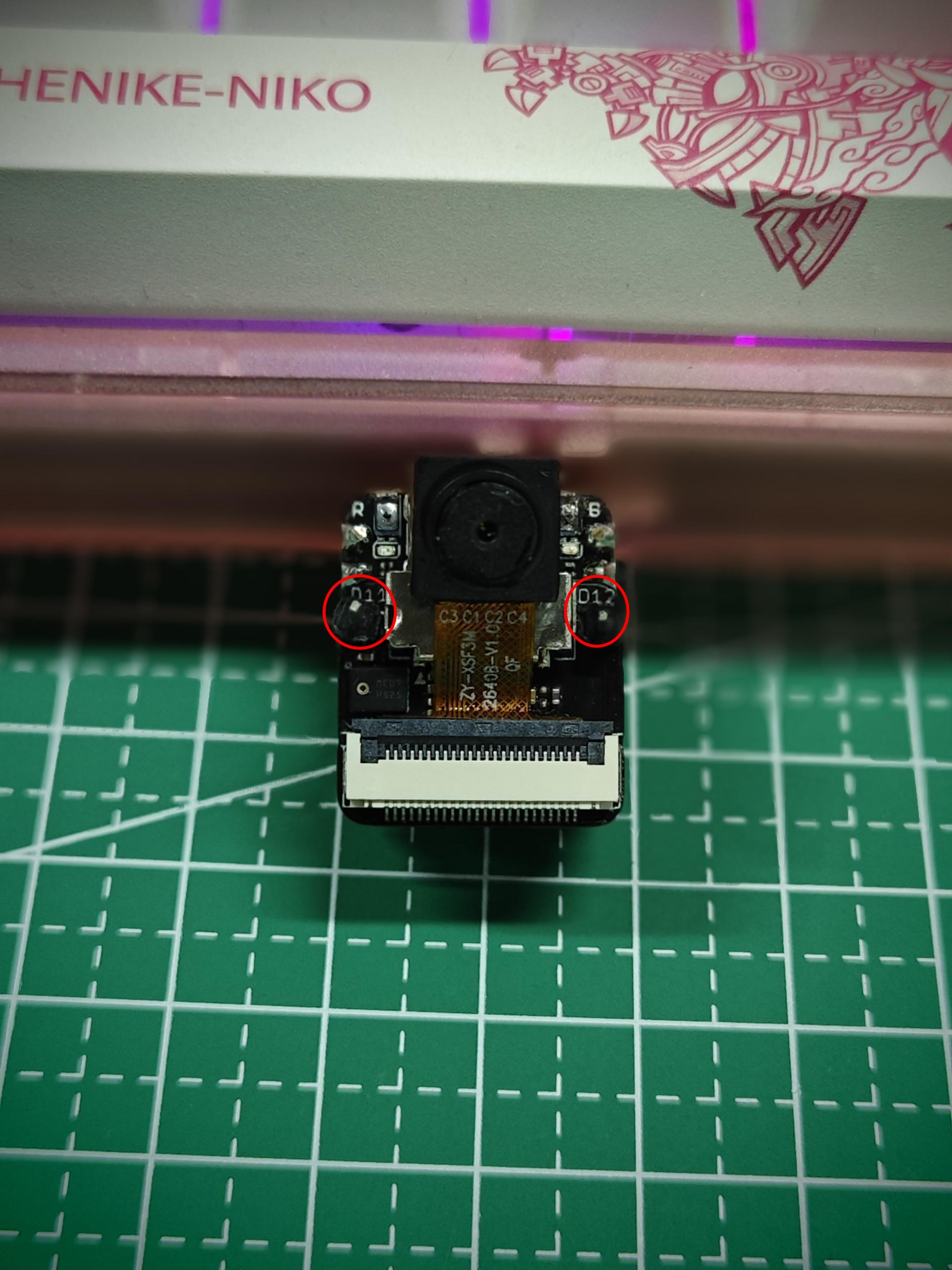
步骤 1. 切断 J1 和 J2 之间的连接
由于 ESP32-S3 的引脚数量有限,Sense 扩展板上的 D11 和 D12 默认保留给麦克风使用。如果你确实需要将 D11 和 D12 用于其他用途,可以将 Sense 扩展板翻过来,用一把锋利的刀沿着两个焊盘之间的白线切断 J1 和 J2 之间的连接。
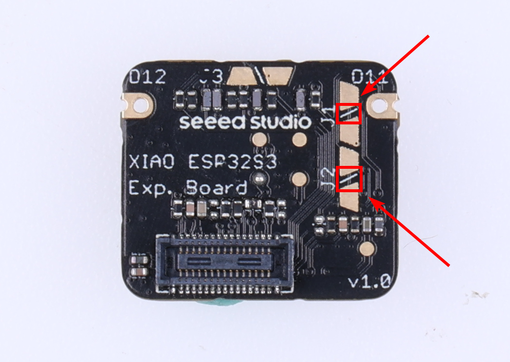
从图片中可以看出,由于 XIAO 的空间限制,许多走线布局非常紧凑。因此,在切断 J1 和 J2 之间的连接时,请务必非常小心,不要切到白线之外,否则可能会导致开发板无法正常工作!
虽然 XIAO ESP32-S3 将 GPIO41 和 GPIO42 分配给 A11 和 A12 引脚,但由于 ESP32-S3 芯片本身的特性,A11 和 A12 引脚不支持 ADC 功能。请务必加以区分和辨别。
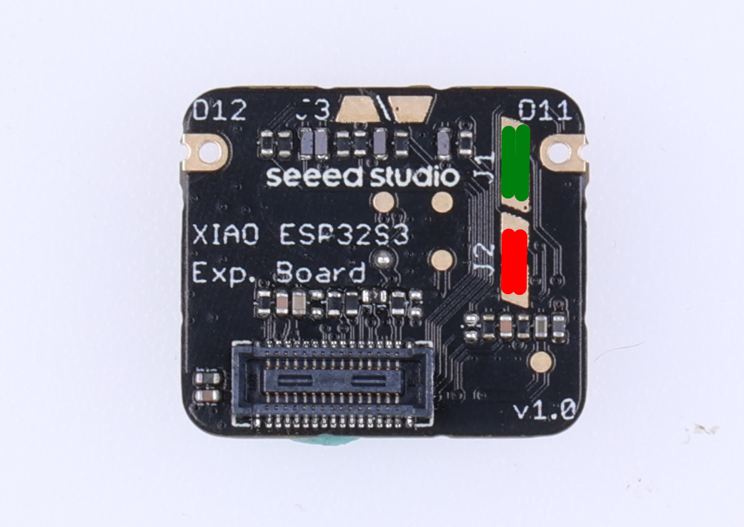
在你切断 J1 和 J2 之间的连接后,扩展板上的麦克风功能将不再可用。如果你需要使用麦克风功能,则不能同时使用 D11 和 D12 引脚。在这种情况下,你可以分别给 J1 和 J2 的两个焊盘上锡,以恢复麦克风功能。如下面图片所示,分别给红色和绿色区域焊接。
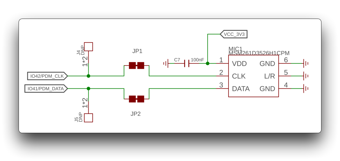
关于实际电路原理图,请参考下图:
步骤 2. 硬件准备
| Seeed Studio XIAO ESP32-S3 Sense | Grove - Relay |
|---|---|
| |
步骤 3. 软件实现
下面的程序每隔 500 毫秒切换一次继电器。将继电器的 SIG 引脚连接到扩展板的 GPIO42 接口。
const int relayPin = 42;

void setup() {
  // initialize the Relay pin as an output:
  pinMode(relayPin, OUTPUT);
}

void loop() {
    // turn Relay on:
    digitalWrite(relayPin, HIGH);
    delay(500);
    // turn Relay off:
    digitalWrite(relayPin, LOW);
    delay(500);
}
上述方法同样适用于 Digital as PWM 和 Analog 部分。你只需要修改你想要使用的扩展板引脚编号。这里不再赘述。
对于 XIAO ESP32-S3 Sense 上新增的两个引脚 D11 和 D12,我们尚未对这些引脚进行宏定义。也就是说,你目前还不能使用 D11/A11 或 D12/A12 来控制这两个引脚,但你可以分别通过 GPIO 编号 GPIO42 和 GPIO41 来控制这两个引脚。我们会尽快提交这两个引脚的宏定义,一旦提交完成,你就可以使用 D/A 形式的引脚定义。
数字引脚作为 PWM 使用
XIAO ESP32-S3 上的所有 GPIO 引脚都支持 PWM 输出。因此,你可以使用任意引脚输出 PWM 来调节灯光亮度、控制舵机以及实现其他功能。
硬件准备
| Seeed Studio XIAO ESP32-S3 | Seeed Studio XIAO ESP32-S3 Sense | Seeed Studio Expansion Base for XIAO with Grove OLED | Grove - Variable Color LED |
|---|---|---|---|
| | |  |
请将 XIAO ESP32-S3 或 Sense 安装到扩展板上,然后使用 Grove 线缆将 Variable Color LED 连接到扩展板的 A0/D0 接口。最后,通过 USB-C 线缆将 XIAO 连接到电脑。
软件实现
在本示例中,我们将演示如何使用 PWM 输出来控制灯光的亮度。
int LED_pin = D0;    // LED connected to digital pin 10

void setup() {
  // declaring LED pin as output
  pinMode(LED_pin, OUTPUT);
}

void loop() {
  // fade in from min to max in increments of 5 points:
  for (int fadeValue = 0 ; fadeValue <= 255; fadeValue += 5) {
    // sets the value (range from 0 to 255):
    analogWrite(LED_pin, fadeValue);
    // wait for 30 milliseconds to see the dimming effect
    delay(30);
  }

  // fade out from max to min in increments of 5 points:
  for (int fadeValue = 255 ; fadeValue >= 0; fadeValue -= 5) {
    // sets the value (range from 0 to 255):
    analogWrite(LED_pin, fadeValue);
    // wait for 30 milliseconds to see the dimming effect
    delay(30);
  }
}
如果程序运行成功,你将看到如下运行效果。
模拟量
在 XIAO ESP32-S3 上,11 个内置 GPIO 引脚中,除用于串行通信的 D6 和 D7 引脚外,其余 9 个引脚都支持模拟功能。你可以使用这些具有模拟功能的 GPIO 引脚来读取输出模拟信号的传感器的数值,例如氧气传感器、光强传感器等。
虽然 XIAO ESP32-S3 将 GPIO41 和 GPIO42 分配给 A11 和 A12 引脚,但由于 ESP32-S3 芯片本身的特性,A11 和 A12 引脚不支持 ADC 功能。请务必加以区分和辨别。
硬件准备
| Seeed Studio XIAO ESP32-S3 | Seeed Studio XIAO ESP32-S3 Sense | Seeed Studio Expansion Base for XIAO with Grove OLED | Grove - Oxygen Sensor |
|---|---|---|---|
| | |  |
请将 XIAO ESP32-S3 或 Sense 安装到扩展板上,然后使用 Grove 线缆将 Oxygen Sensor 连接到扩展板上的 A0/D0 接口。最后,通过 USB-C 线缆将 XIAO 连接到电脑。
软件实现
在下面的程序中,我们将使用 analogRead() 方法读取传感器的模拟值,并通过 Serial 接口打印传感器结果。
// Grove - Gas Sensor(O2) test code
// Note:
// 1. It need about about 5-10 minutes to preheat the sensor
// 2. uncomment the module name you're using
// 3. modify VRefer if needed

// comment useless one
// #define MIX8410
#define O2_W2

#ifdef MIX8410
  #define O2_COEFFICIENT 0.21
#elif defined(O2_W2)
  #define O2_COEFFICIENT 0.087
#endif

const float VRefer = 3.34;       // voltage of adc reference
const int pinAdc   = A0;

void setup()
{
    // put your setup code here, to run once:
    Serial.begin(9600);
    Serial.println("Grove - Oxygen Sensor(MIX8410) Test Code...");
}

void loop()
{
    // put your main code here, to run repeatedly:
    float Vout =0;
    Serial.print("Vout =");

    Vout = readO2Vout();
    Serial.print(Vout);
    Serial.print(" V, Concentration of O2 is ");
    Serial.println(readConcentration());
    delay(500);
}

float readO2Vout()
{
    long sum = 0;
    for(int i=0; i<32; i++)
    {
        sum += analogRead(pinAdc);
    }

    sum >>= 5;

    float MeasuredVout = sum * (VRefer / 1023.0);
    return MeasuredVout;
}

float readConcentration()
{
    // Vout samples are with reference to 3.3V
    float MeasuredVout = readO2Vout();

    //float Concentration = FmultiMap(MeasuredVout, VoutArray,O2ConArray, 6);
    //when its output voltage is 2.0V,
    float Concentration = MeasuredVout * O2_COEFFICIENT / 2.0;
    float Concentration_Percentage=Concentration*100;
    return Concentration_Percentage;
}
如果你想使用某个引脚的模拟功能,应当在引脚编号前加上字母 “A” 作为前缀,例如 A4、A5。相反,如果你想使用数字功能,则应在引脚编号前加上字母 “D” 作为前缀,例如 D4、D5。
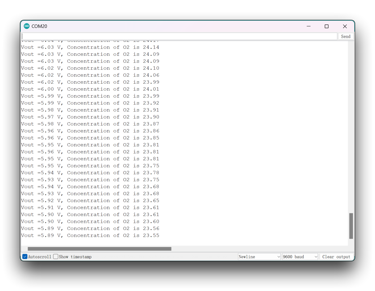
上传程序后,在 Arduino IDE 中打开 Serial Monitor,并将波特率设置为 9600。等待氧气传感器预热完成后,你就可以看到准确的氧气浓度数值。
串口
在使用 Arduino IDE 进行开发时,串口通信是许多项目中必不可少的一部分。要在 Arduino IDE 中使用 Serial,首先需要打开 Serial Monitor 窗口。这可以通过点击工具栏中的 Serial Monitor 图标,或按下 Ctrl+Shift+M 快捷键来完成。
常规用法
一些常用的 Serial 函数包括:
Serial.begin()-- 用于以指定的波特率初始化通信;Serial.print()-- 以可读格式向串口发送数据;Serial.write()-- 向串口发送二进制数据;Serial.available()-- 检查串口中是否有可供读取的数据;Serial.read()-- 从串口读取一个字节的数据;Serial.flush()-- 等待所有要发送的串口数据传输完成。
通过使用这些 Serial 函数,你可以在 Arduino 开发板和电脑之间发送和接收数据,从而为创建交互式项目提供了许多可能性。
下面是一个示例程序:
void setup() {
  // initialize serial communication at 9600 bits per second:
  Serial.begin(9600);
}

void loop() {
  // send data to the serial port
  Serial.println("Hello World!");

  // read data from the serial port
  if (Serial.available() > 0) {
    // read the incoming byte:
    char incomingByte = Serial.read();
    // print the incoming byte to the serial monitor:
    Serial.print("I received: ");
    Serial.println(incomingByte);
  }

  // wait for a second before repeating the loop
  delay(1000);
}
在这段代码中,我们首先在 setup() 函数中使用 Serial.begin() 函数以 9600 的波特率初始化串口通信。然后在 loop() 函数中,我们使用 Serial.print() 函数向串口发送 "Hello World!"。
我们还使用 Serial.available() 函数检查串口中是否有可供读取的数据。如果有,我们使用 Serial.read() 函数读取传入的字节,并将其存储在名为 incomingByte 的变量中。然后,我们使用 Serial.print() 和 Serial.println() 函数在串口监视器中打印出 "I received: ",后面跟上 incomingByte 的值。
最后,我们添加了一个 delay() 函数,在重复循环之前等待一秒钟。这段代码演示了如何在 Arduino IDE 中使用一些常用的 Serial 函数,通过串口发送和接收数据。
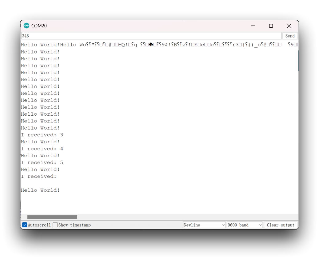
在上传程序后,打开 Arduino IDE 中的串口监视器,并将波特率设置为 9600。你会在串口监视器上看到如下信息,它每秒输出一次“Hello World!”。此外,你还可以通过串口监视器向 XIAO ESP32-S3 发送内容,XIAO 会打印出你发送内容的每一个字节。
Serial1 用法
根据上文中 XIAO ESP32-S3 引脚图中的具体参数,我们可以看到有 TX 引脚和 RX 引脚。 这与 USB 串口通信不同,但用法也非常相似,只是需要额外添加几个参数。 所以接下来,我们将使用芯片引出的引脚进行串口通信。
需要包含的核心函数:
Serial1.begin(BAUD,SERIAL_8N1,RX_PIN,TX_PIN);-- 启用 Serial1,函数原型:<Serial.Type>.begin(unsigned long baud, uint32_t config, int8_t rxPin, int8_t txPin);baud:波特率config:配置位rxPin:接收引脚txPin:发送引脚
值得注意的是,如果我们使用数字引脚端口来定义,这里应为 #define RX_PIN D7、#define TX_PIN D6;如果使用 GPIO 引脚端口来定义,这里应为 #define RX_PIN 44、#define TX_PIN 43,具体参数请参考不同 XIAO 系列的引脚图。
下面是一个示例程序:
#define RX_PIN D7
#define TX_PIN D6
#define BAUD 115200

void setup() {
    Serial1.begin(BAUD,SERIAL_8N1,RX_PIN,TX_PIN);
}

void loop() {
  if(Serial1.available() > 0)
  {
    char incominByte = Serial1.read();
    Serial1.print("I received : ");
    Serial1.println(incominByte);
  }
  delay(1000);
}
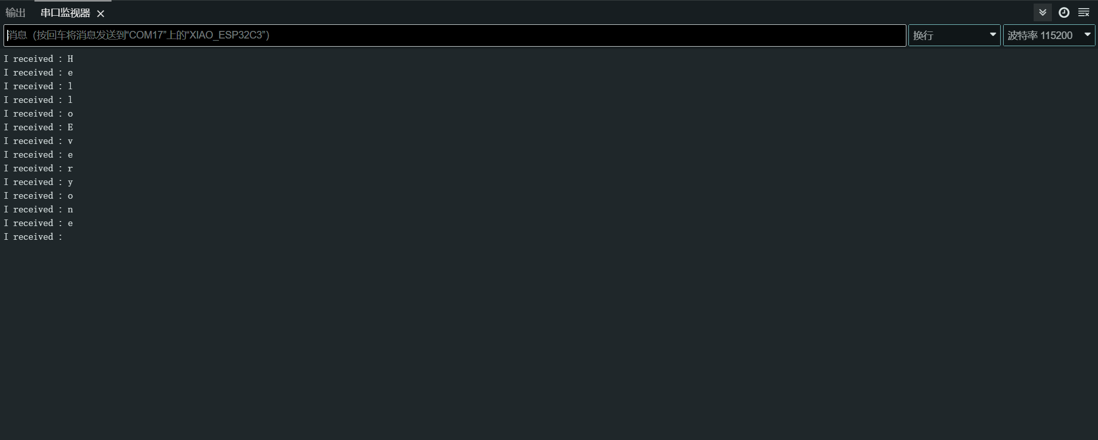
在上传程序后,打开 Arduino IDE 中的串口监视器,并将波特率设置为 115200。然后,你可以通过串口监视器 Serial 向 XIAO ESP32-S3 发送你想要的内容,XIAO 会打印出你发送内容的每一个字节。这里我输入的内容是 “Hello Everyone”,我的结果图如下所示。
软件串口的使用
如果你觉得一个硬件串口不够用,你也可以使用 ESP32 的软件串口功能,将一些引脚设置为软件串口,以扩展串口数量。
当然,我们更推荐使用第二种映射硬件串口的方法,因为这是 ESP32 独有的特性。你可以在 Other Hardware Serial 部分阅读更多内容。
对于 ESP32 系列芯片产品,如果需要使用软件串口,需要单独下载第三方软件串口库。这里提供一个参考。
目前我们推荐使用 EspSoftwareSerial 库的 7.0.0 版本。其他版本可能存在不同程度的问题,导致软件串口无法正常工作。
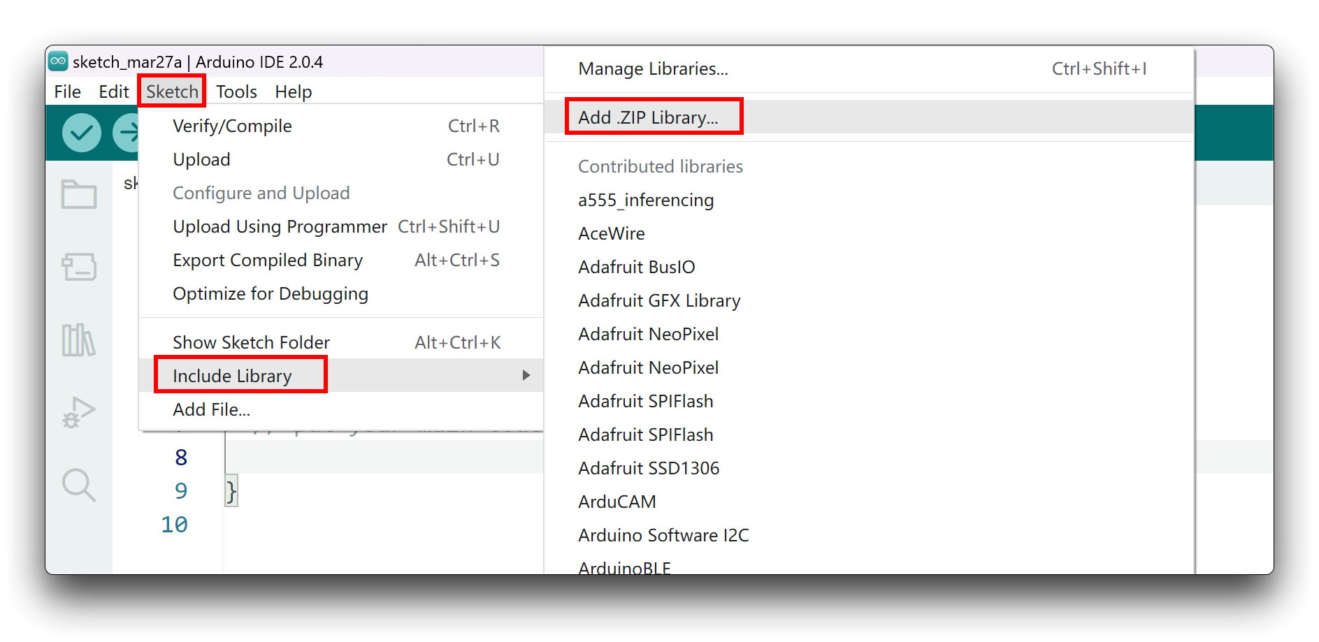
由于你已经下载了 zip 库文件,打开 Arduino IDE,点击 Sketch > Include Library > Add .ZIP Library。选择你刚刚下载的 zip 文件,如果库安装正确,你会在提示窗口中看到 Library added to your libraries,这表示库已成功安装。
接下来,你就可以使用 ESP32 的软件串口了。
如果你的电脑上安装了其他软件串口库,很可能会引起冲突,请自行检查。
#include <SoftwareSerial.h>

SoftwareSerial mySerial(2, 3); // RX, TX

void setup() {
  // initialize serial communication
  Serial.begin(9600);
  while (!Serial);

  // initialize software serial
  mySerial.begin(9600);
}

void loop() {
  // read data from software serial
  if (mySerial.available()) {
    char data = mySerial.read();
    Serial.print("Received data: ");
    Serial.println(data);
  }

  // write data to software serial
  mySerial.print("Hello World!");

  // wait for a second before repeating the loop
  delay(1000);
}
在这个程序中,我们首先包含 SoftwareSerial.h 库以使用软件串口。然后,我们创建了一个名为 mySerial 的新的 SoftwareSerial 对象,分别使用引脚 2 和 3 作为 RX 和 TX。
在 setup() 函数中,我们初始化了硬件串口(Serial.begin())和软件串口(mySerial.begin())。
在 loop() 函数中,我们使用 mySerial.available() 函数检查软件串口是否有可读取的数据。如果有,我们使用 mySerial.read() 函数读取传入的字节,并将其存储在名为 data 的变量中。然后我们使用 Serial.print() 和 Serial.println() 函数在硬件串口上打印“Received data: ”,并在其后输出 data 的值。
我们还使用 mySerial.print() 函数向软件串口写入“Hello World!”。这会将数据从 XIAO 发送到连接在软件串口上的设备。
最后,我们添加了一个 delay() 函数,在重复循环之前等待一秒钟。
请注意,要在 ESP32-S3 上使用软件串口,你需要选择未被其他用途占用的合适 RX 和 TX 引脚。在本示例中,我们使用了 9 和 10 引脚分别作为 RX 和 TX。
其他硬件串口
ESP32S3 一共有三个 UART 通信接口,编号从 0 到 2,分别为 UART0、UART1 和 UART2。这三个串口的引脚都不是固定的,可以被重新映射到任意 IO 端口。
默认情况下,我们不使用 UART0,因为它被用于 USB 串口通信。你可以通过自定义硬件串口映射来使用其他硬件串口。
// Need this for the lower level access to set them up.
#include <HardwareSerial.h>

//Define two Serial devices mapped to the two internal UARTs
HardwareSerial MySerial0(0);
HardwareSerial MySerial1(1);

void setup()
{
    // For the USB, just use Serial as normal:
    Serial.begin(115200);

    // Configure MySerial0 on pins TX=D6 and RX=D7 (-1, -1 means use the default)
    MySerial0.begin(9600, SERIAL_8N1, -1, -1);
    MySerial0.print("MySerial0");

    // And configure MySerial1 on pins RX=D9, TX=D10
    MySerial1.begin(115200, SERIAL_8N1, D9, D10);
    MySerial1.print("MySerial1");
}

void loop()
{

}
下面我们将以正在销售的 60GHz mmWave Sensor - Human Resting Breathing and Heartbeat Module 为例,说明如何使用 D9 和 D10 硬件串口以及 USB 串口。
请准备好以下物品。
| Seeed Studio XIAO ESP32-S3 | Seeed Studio XIAO ESP32-S3 Sense | 60GHz mmWave Sensor - Human Resting Breathing and Heartbeat Module |
|---|---|---|
| |  |
将传感器库下载到你的电脑上,并将其添加到 Arduino IDE 中。
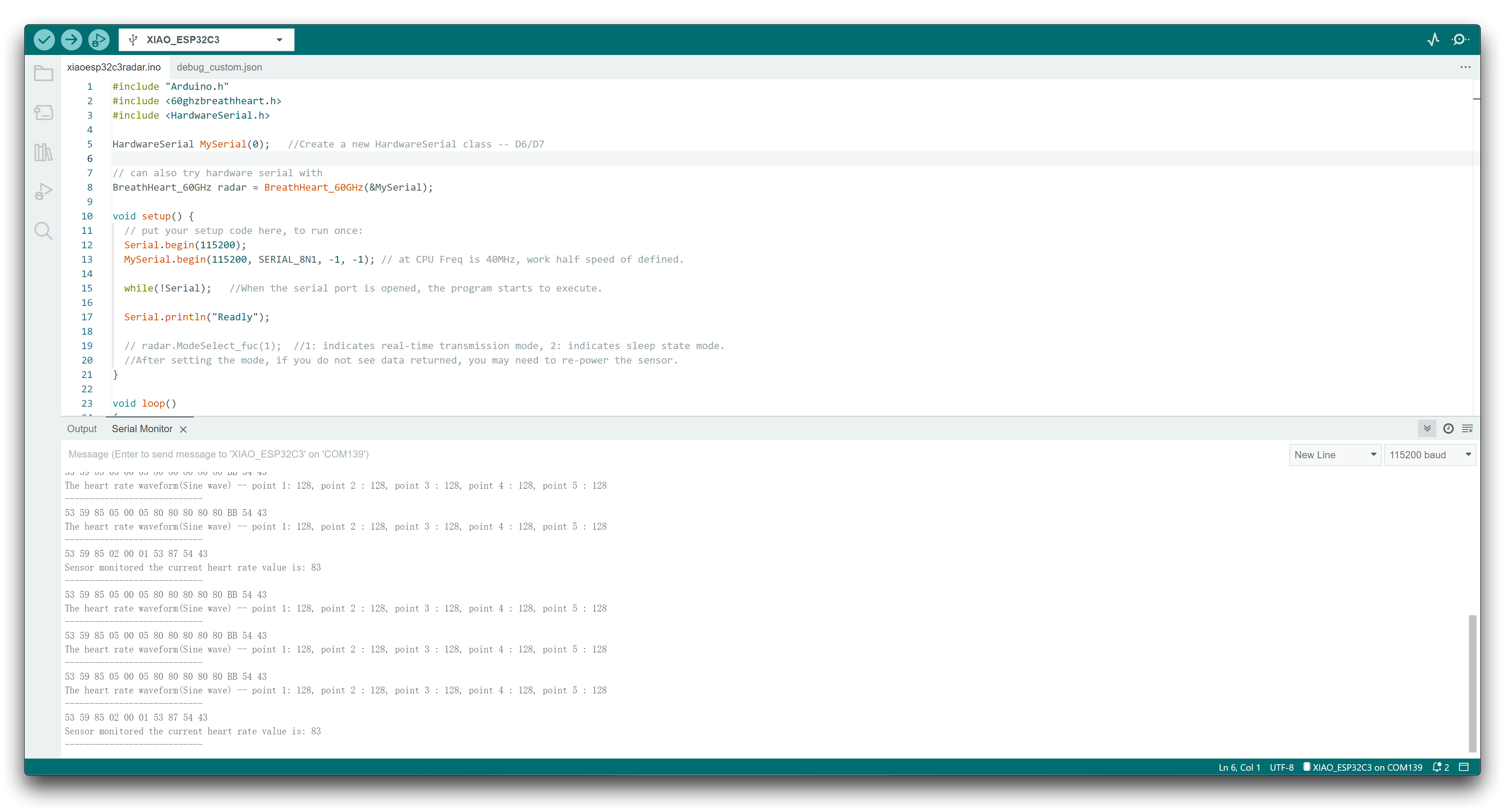
在这里,我们希望解析心跳和呼吸数据信息,然后你可以像这样重写你的程序。
#include "Arduino.h"
#include <60ghzbreathheart.h>
#include <HardwareSerial.h>

HardwareSerial MySerial(0);   //Create a new HardwareSerial class -- D6/D7

// can also try hardware serial with
BreathHeart_60GHz radar = BreathHeart_60GHz(&MySerial);

void setup() {
  // put your setup code here, to run once:
  Serial.begin(115200);
  MySerial.begin(115200, SERIAL_8N1, 9, 10); // at CPU Freq is 40MHz, work half speed of defined.

  while(!Serial);   //When the serial port is opened, the program starts to execute.

  Serial.println("Readly");

  // radar.ModeSelect_fuc(1);  //1: indicates real-time transmission mode, 2: indicates sleep state mode.
  //After setting the mode, if you do not see data returned, you may need to re-power the sensor.
}

void loop()
{
  // put your main code here, to run repeatedly:
  radar.Breath_Heart();           //Breath and heartbeat information output
  if(radar.sensor_report != 0x00){
    switch(radar.sensor_report){
      case HEARTRATEVAL:
        Serial.print("Sensor monitored the current heart rate value is: ");
        Serial.println(radar.heart_rate, DEC);
        Serial.println("----------------------------");
        break;
      case HEARTRATEWAVE:  //Valid only when real-time data transfer mode is on
        Serial.print("The heart rate waveform(Sine wave) -- point 1: ");
        Serial.print(radar.heart_point_1);
        Serial.print(", point 2 : ");
        Serial.print(radar.heart_point_2);
        Serial.print(", point 3 : ");
        Serial.print(radar.heart_point_3);
        Serial.print(", point 4 : ");
        Serial.print(radar.heart_point_4);
        Serial.print(", point 5 : ");
        Serial.println(radar.heart_point_5);
        Serial.println("----------------------------");
        break;
      case BREATHNOR:
        Serial.println("Sensor detects current breath rate is normal.");
        Serial.println("----------------------------");
        break;
      case BREATHRAPID:
        Serial.println("Sensor detects current breath rate is too fast.");
        Serial.println("----------------------------");
        break;
      case BREATHSLOW:
        Serial.println("Sensor detects current breath rate is too slow.");
        Serial.println("----------------------------");
        break;
      case BREATHNONE:
        Serial.println("There is no breathing information yet, please wait...");
        Serial.println("----------------------------");
        break;
      case BREATHVAL:
        Serial.print("Sensor monitored the current breath rate value is: ");
        Serial.println(radar.breath_rate, DEC);
        Serial.println("----------------------------");
        break;
      case BREATHWAVE:  //Valid only when real-time data transfer mode is on
        Serial.print("The breath rate waveform(Sine wave) -- point 1: ");
        Serial.print(radar.breath_point_1);
        Serial.print(", point 2 : ");
        Serial.print(radar.breath_point_2);
        Serial.print(", point 3 : ");
        Serial.print(radar.breath_point_3);
        Serial.print(", point 4 : ");
        Serial.print(radar.breath_point_4);
        Serial.print(", point 5 : ");
        Serial.println(radar.breath_point_5);
        Serial.println("----------------------------");
        break;
    }
  }
  delay(200);                       //Add time delay to avoid program jam
}
请上传程序,然后打开串口监视器并将波特率设置为 115200。
如果一切顺利,你会在串口监视器上看到数据信息。
IIC
XIAO ESP32-S3 具有一个 I2C 接口,可用于许多传感器的数据传输和解析,也可以用于驱动一些 OLED 屏幕。
硬件准备
| Seeed Studio XIAO ESP32-S3 | Seeed Studio XIAO ESP32-S3 Sense | Seeed Studio Expansion Base for XIAO with Grove OLED |
|---|---|---|
| | |
XIAO 扩展板上的 OLED 显示屏使用 I2C 协议,并通过板载的 I2C 电路连接到 XIAO 的 I2C 接口。因此,我们可以直接将 XIAO 插到扩展板上,并通过编程在屏幕上显示内容。
软件实现
本示例介绍如何使用 Seeed Studio Expansion Base for XIAO ESP32-S3 上的 OLED 显示屏。
步骤 1. 将 Seeed Studio XIAO ESP32-S3 安装到扩展板上,然后连接 Type-C 线缆
步骤 2. 安装 u8g2 库
步骤 3. 复制代码并粘贴到 Arduino IDE 中,然后上传
#include <Arduino.h>
#include <U8x8lib.h>
#include <Wire.h>

U8X8_SSD1306_128X64_NONAME_HW_I2C u8x8(/* clock=*/ SCL, /* data=*/ SDA, /* reset=*/ U8X8_PIN_NONE);   // OLEDs without Reset of the Display

void setup(void) {
  u8x8.begin();
  u8x8.setFlipMode(1);   // set number from 1 to 3, the screen word will rotary 180
}

void loop(void) {
  u8x8.setFont(u8x8_font_chroma48medium8_r);
  u8x8.setCursor(0, 0);
  u8x8.print("Hello World!");
}
在代码的前几行中,我们包含了所需的库,例如 Arduino.h、U8x8lib.h 和 Wire.h。U8x8lib.h 库提供了控制 OLED 显示屏的函数,而 Wire.h 库提供了用于 I2C 通信的函数。
在 setup() 函数中,我们使用 u8x8.begin() 函数初始化 OLED 显示屏。我们还使用 u8x8.setFlipMode() 函数设置显示屏的翻转模式,将屏幕旋转 180 度。
在 loop() 函数中,我们使用 u8x8.setFont() 函数设置字体,并使用 u8x8.setCursor() 函数指定显示屏上光标的位置。最后,我们使用 u8x8.print() 函数在 OLED 显示屏上显示字符串 "Hello World!"。
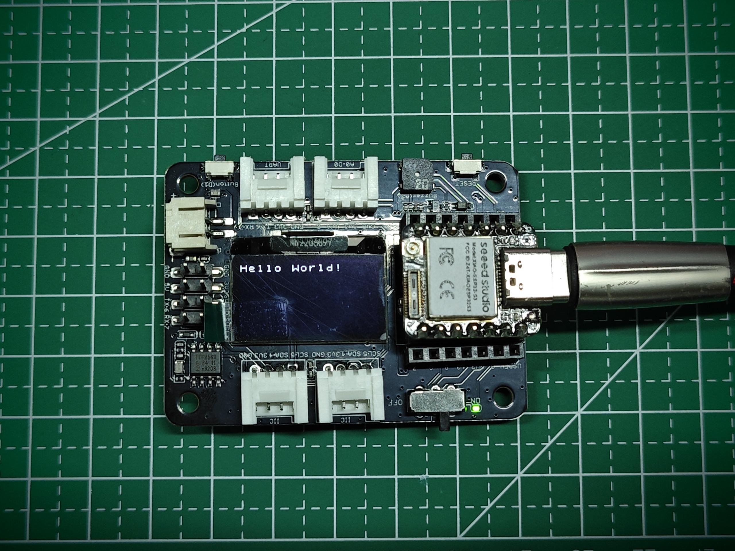
如果你向 XIAO ESP32-S3 上传程序,你将在扩展板上的 OLED 显示屏上看到显示的内容。
SPI
ESP32-S3 芯片集成了多种外设,其中包括可用于连接外部 SPI 设备(如闪存、显示屏、传感器等)的 SPI 接口。ESP32-S3 还支持高速 SPI 传输模式,最高 SPI 传输速率可达 80 MHz,能够满足大多数 SPI 设备的数据传输需求。
硬件准备
| Seeed Studio XIAO ESP32-S3 | Seeed Studio XIAO ESP32-S3 Sense | Grove - OLED Display 1.12 (SH1107) V3.0 - SPI/IIC |
|---|---|---|
| | _V3.0/img/10402050_Main-02.png) |
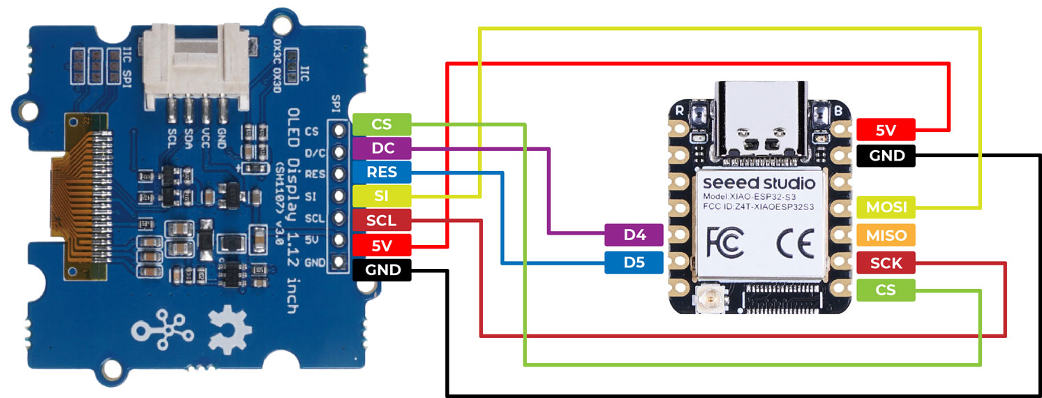
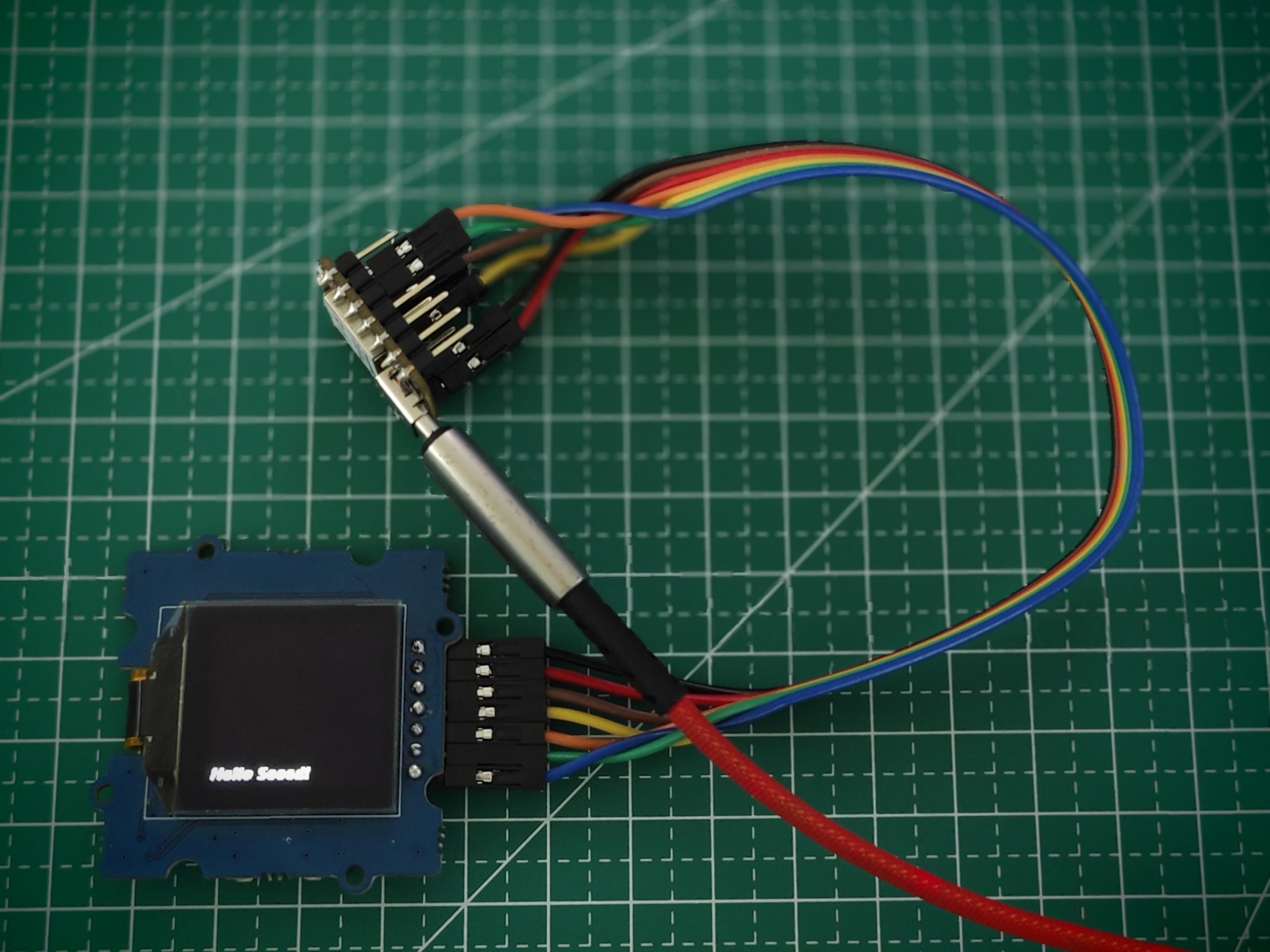
按照上述说明准备好硬件后,使用跳线将 XIAO 与 OLED 的 SPI 接口连接起来。接线方式请参考下图。
软件实现
接下来,我们将以下程序作为示例,介绍如何使用 SPI 接口控制 OLED 屏幕显示。
安装 u8g2 库。
#include <Arduino.h>
#include <U8g2lib.h>
#include <SPI.h>
#include <Wire.h>

U8G2_SH1107_128X128_1_4W_HW_SPI u8g2(U8G2_R3, /* cs=*/ D7, /* dc=*/ D4, /* reset=*/ D5);

void setup(void) {
  u8g2.begin();
}

void loop(void) {
  u8g2.firstPage();

  do {
    u8g2.setFont(u8g2_font_luBIS08_tf);
    u8g2.drawStr(0,24,"Hello Seeed!");
  } while ( u8g2.nextPage() );
}
在 setup() 函数中,使用合适的构造函数参数实例化 U8G2_SH1107_128X128_1_4W_HW_SPI 类,这些参数指定了用于片选(cs)、数据/命令(dc)和复位的引脚。然后调用 u8g2.begin() 函数来初始化显示屏。
在 loop() 函数中,使用 u8g2.firstPage()、u8g2.setFont() 和 u8g2.drawStr() 函数来用新内容更新显示屏。u8g2.firstPage() 函数用于为写入设置显示缓冲区,而 u8g2.nextPage() 则用于显示更新后的内容。do-while 循环确保内容会持续显示,直到程序停止。
总体来说,该代码演示了如何使用 U8g2 库来控制 OLED 显示屏并在其上显示文本。
适用于 Sense
如果你购买的是 Sense 版本并需要连接扩展板,请注意扩展板上的 SD 卡会占用 SPI 引脚,这可能会导致 SPI 引脚不可用。
Sense 扩展板上提供的焊盘接口允许用户选择所需的功能。其中,J3 焊盘的功能是启用 SPI 或 SD 卡功能。
| 如果你想使用 SPI 引脚 / 禁用扩展板上的 SD 卡 | 如果你想启用扩展板上的 SD 卡 / 禁用 SPI 引脚 |
|---|---|
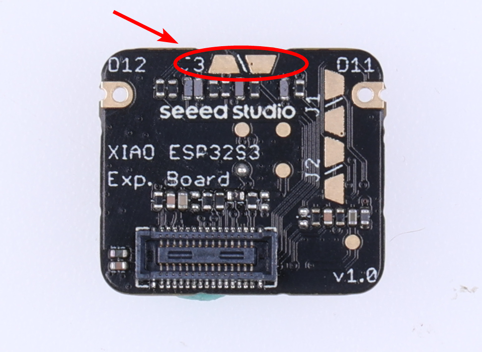 |  |
| 沿着白色细线切断,以断开焊盘连接。 | 将两个焊盘焊接在一起。 |
从图中可以看出,由于 XIAO 的空间限制,很多走线布局非常紧凑。因此,在切断 J3 连接时,请务必非常小心,不要切到白线外,否则可能会导致开发板无法正常工作!
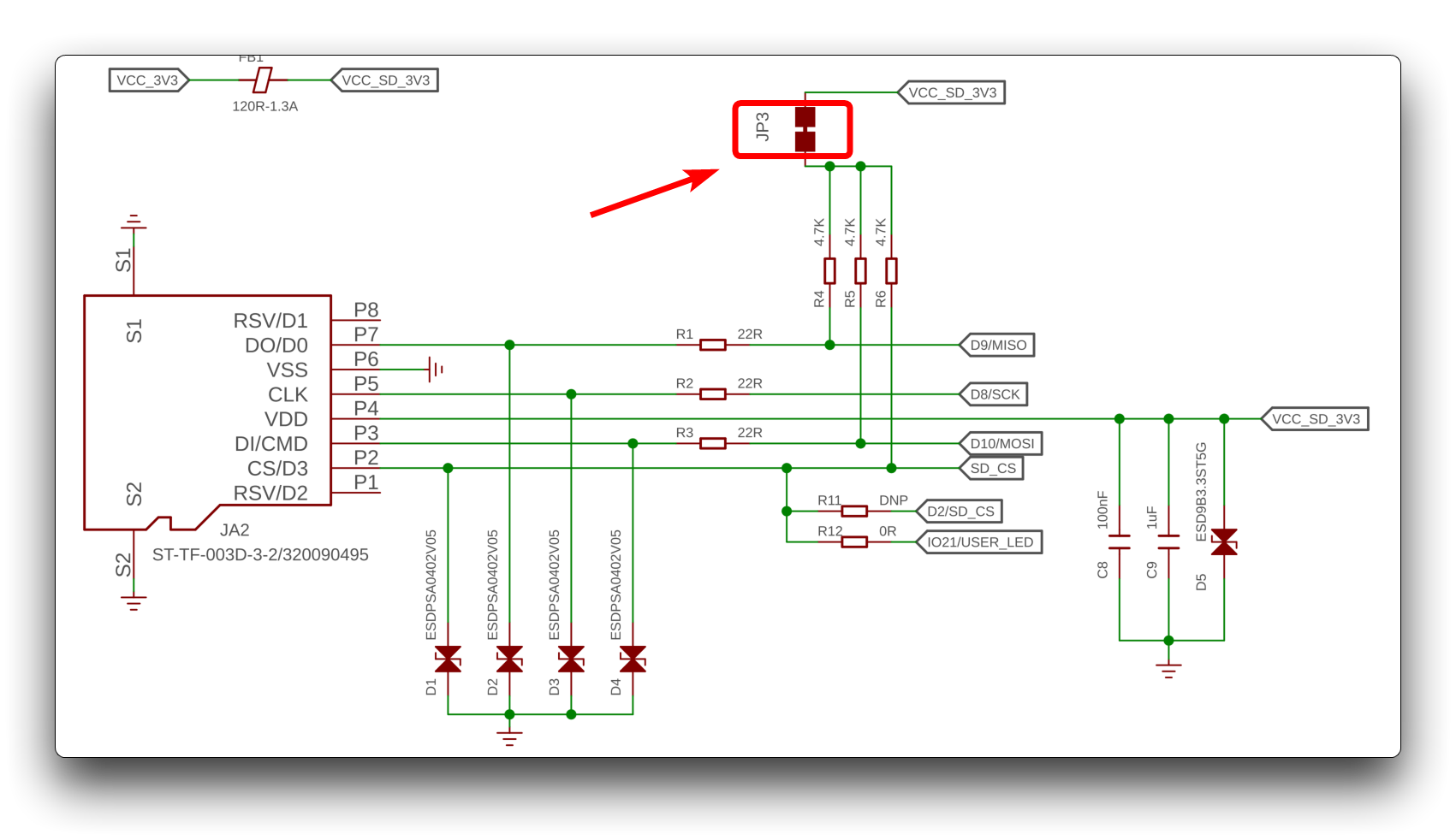
出于通俗描述的考虑,上文只是简单地将 J3 描述为一个控制 SD 卡功能开关的接口,但这实际上并不准确。实际的电路连接如下图所示。切断 J3 实际上是将 R4 到 R6 的上拉电阻断开,这才是 SD 卡功能被禁用而 SPI 功能恢复正常的主要原因。
触摸引脚
除了上述常见的功能引脚外,XIAO ESP32-S3/XIAO ESP32-S3 Sense 还具有 9 个触摸检测引脚 A0A5、A8A10。
我们可以通过读取引脚的模拟值来判断该引脚是否被触摸,非常方便。下面的程序用于检测引脚 A5 是否被触摸。
const int touch_pin = A5;

void setup(void) {
  Serial.begin(9600);
}

void loop(void) {
  Serial.print("Touch value: ");
  Serial.println(analogRead(touch_pin));
  delay(1000);
}
上传程序后,打开串口监视器并将波特率设置为 9600。然后触摸引脚 A5,你会发现模拟读取值会明显大于触摸前的数值。
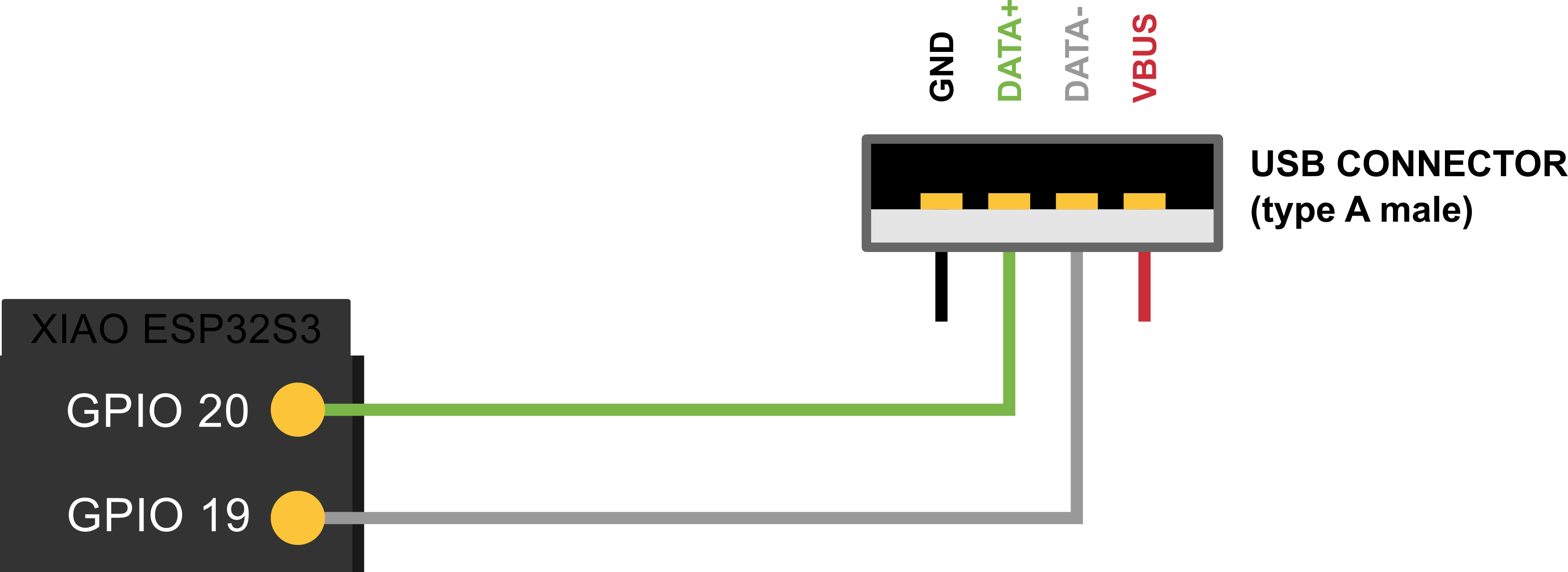
USB 引脚
ESP32-S3 是一款集成了 Wi-Fi 和蓝牙功能的微控制器,其 D+ 和 D- 引脚用于支持 USB 通信。具体来说,这两个引脚是差分信号线,用于在 USB 2.0 设备与主机之间进行高速数据传输。
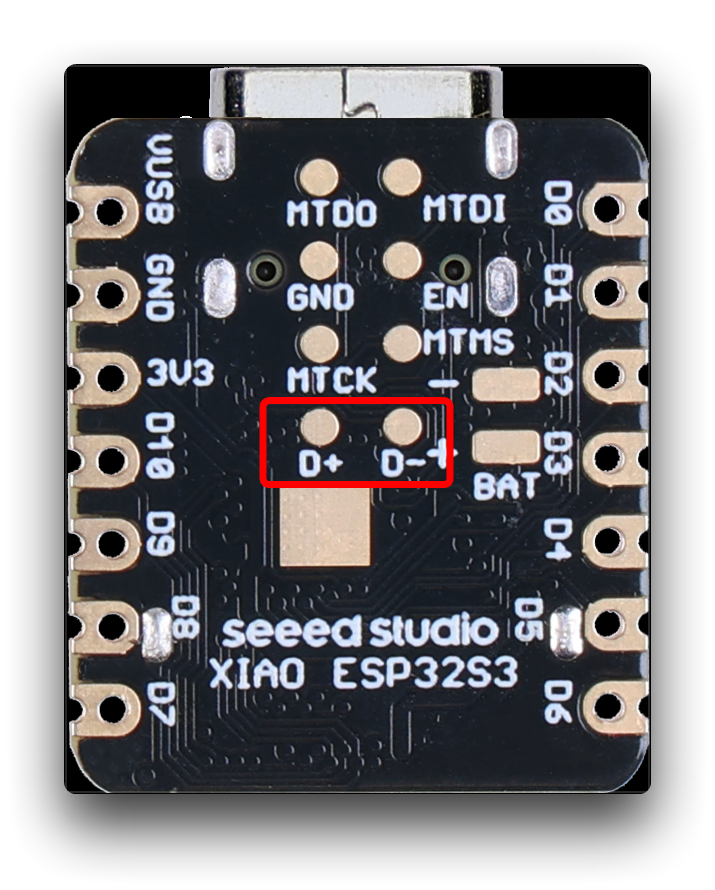
D+ 引脚是用于发送数据的正极信号线,而 D- 引脚是用于发送数据的负极信号线。当 USB 设备连接到主机时,主机会通过检测这两个引脚上的电压变化来判断设备的连接状态和传输速度。在数据传输过程中,D+ 和 D- 引脚交替传输数据位和同步信号,以实现可靠的数据传输。
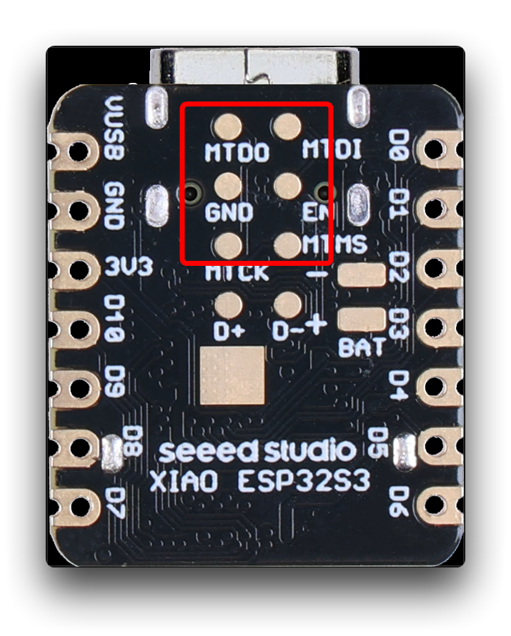
JTAG 引脚
ESP32-S3 的 JTAG(Joint Test Action Group)接口是一个调试和测试接口,可用于在开发、调试和测试过程中进行非常底层的硬件调试和编程。JTAG 接口包括一组标准信号线,包括时钟线、数据输入线、数据输出线、测试模式选择线、测试模式时钟线等。
ESP32-S3 的 JTAG 接口可以用于以下目的:
-
调试:JTAG 接口可用于在 ESP32-S3 芯片中进行调试和单步执行,帮助开发者发现并解决代码错误。
-
烧录程序:通过 JTAG 接口,可以将程序或调试固件加载到 ESP32-S3 芯片中。
-
读取 CPU 状态:可以使用 JTAG 接口读取 ESP32-S3 芯片的 CPU 状态、内存内容和寄存器值,用于调试和测试。
需要注意的是,使用 JTAG 接口需要专用的硬件设备和软件工具,以及相应的专业知识和技能。因此,一般情况下,JTAG 接口只在开发、调试和测试等特定场景中使用。对于普通用户来说,使用 ESP32-S3 的其他功能和接口已经足够。
如果你想了解更多关于 JTAG 调试的信息,请阅读官方的 ESP32 文档。
故障排查
Q1:为什么我在使用串口监视器时会出现以下错误?
A:如果你遇到此类错误,请打开 USB CDC On Boot 开关。
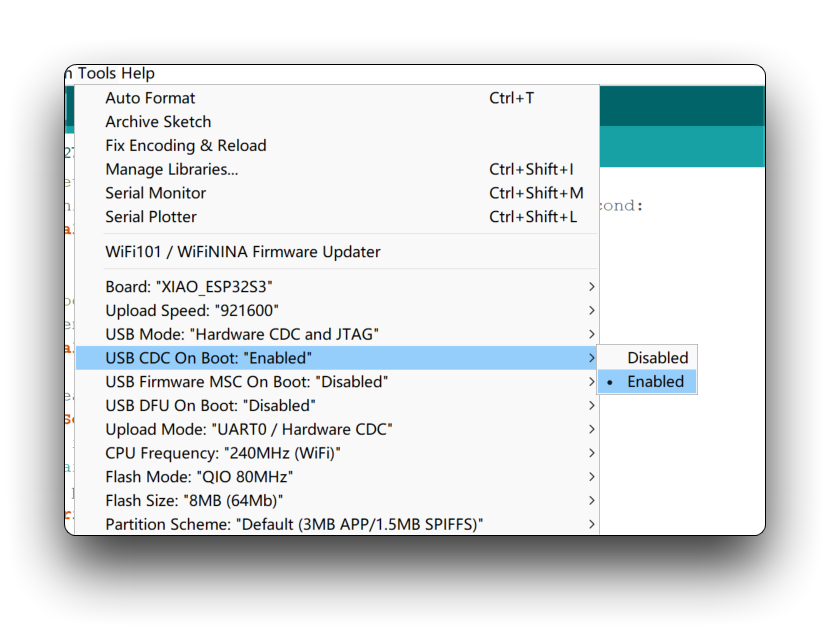
这个问题在 Arduino IDE 2.x 中也可能表现为串口输出为空,也可能是同样的原因导致的。
Q2:ESP-32 支持或不支持哪些特性?
A:以下是 ESP32 提供的已支持/不支持特性列表。截止日期为 2023 年 4 月 10 日。
| 外设 | ESP32 | ESP32-S2 | ESP32-C3 | ESP32-S3 | 备注 |
|---|---|---|---|---|---|
| ADC | Yes | Yes | Yes | Yes | |
| Bluetooth | Yes | Not Supported | Not Supported | Not Supported | Bluetooth Classic |
| BLE | Yes | Not Supported | Yes | Yes | |
| DAC | Yes | Yes | Not Supported | Not Supported | |
| Ethernet | Yes | Not Supported | Not Supported | Not Supported | (*) |
| GPIO | Yes | Yes | Yes | Yes | |
| Hall Sensor | Yes | Not Supported | Not Supported | Not Supported | |
| I2C | Yes | Yes | Yes | Yes | |
| I2S | Yes | Yes | Yes | Yes | |
| LEDC | Yes | Yes | Yes | Yes | |
| Motor PWM | No | Not Supported | Not Supported | Not Supported | |
| Pulse Counter | No | No | No | No | |
| RMT | Yes | Yes | Yes | Yes | |
| SDIO | No | No | No | No | |
| SDMMC | Yes | Not Supported | Not Supported | Yes | |
| Timer | Yes | Yes | Yes | Yes | |
| Temp. Sensor | Not Supported | Yes | Yes | Yes | |
| Touch | Yes | Yes | Not Supported | Yes | |
| TWAI | No | No | No | No | |
| UART | Yes | Yes | Yes | Yes | |
| USB | Not Supported | Yes | Yes | Yes | ESP32-C3 only CDC/JTAG |
| Wi-Fi | Yes | Yes | Yes | Yes |
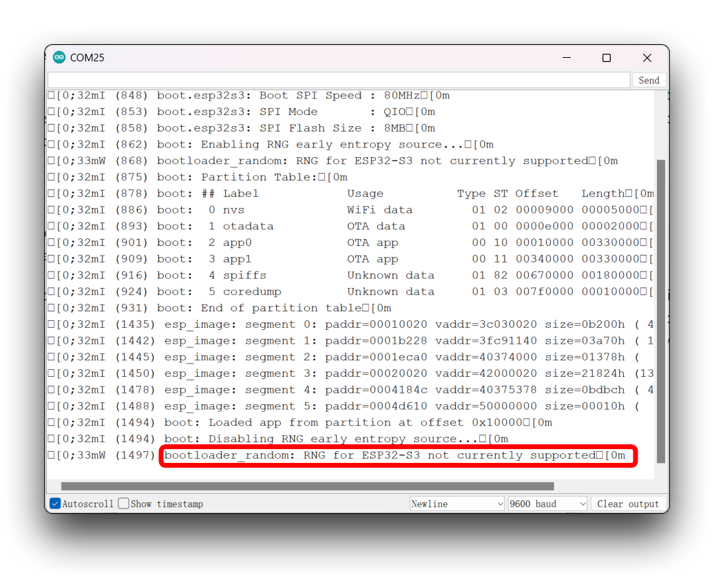
Q3:为什么我总能在串口监视器中看到芯片的调试信息?
A:你可以尝试使用以下方法关闭调试信息的输出,在 Arduino IDE 中选择 Tool -> Core Debug Level: -> None。
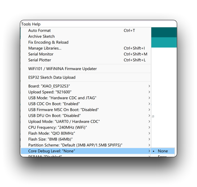
然而,这种方法并不总是有效,实际上,ESP32-S3 的调试信息总是从串口打印输出,这是无法改变的。请多包涵,它只是太迫切地想让你知道它正在正常工作。
Q4:为什么我切断了 J3 的连接,但测试时 D8 和 D9 引脚仍然为高电平?向 microSD 卡写入数据仍然有一定成功概率?
从 SD 卡设计的角度来看,正确的电路必须带有上拉电阻才能使 microSD 卡正常工作。如果你发现切断 J3 后引脚电平以及卡的读写仍然正常,这可能只是一个幸运的情况,我们并不建议你在这种情况下对卡进行读写,这可能会导致已写入数据丢失的问题。而在切断 J3 之后,可以通过写入低电平来改变 D8 和 D9 引脚的电平。
技术支持与产品讨论
感谢你选择我们的产品!我们将为你提供多种支持,以确保你在使用我们产品的过程中尽可能顺利。我们提供多种沟通渠道,以满足不同的偏好和需求。