Seeed Studio XIAO ESP32S3 Sense 摄像头使用
本教程内容仅适用于 Seeed Studio XIAO ESP32S3 Sense。
在本教程中,我们将带你一步步使用 XIAO ESP32S3 Sense 上的摄像头模块。本教程分为以下几个部分:首先,我们会讲解 ESP32 提供的摄像头功能及其作用;其次,我们将从拍照和录像两个维度介绍如何使用摄像头;最后,我们会围绕拍照和录像制作一些有趣的项目。
| Seeed Studio XIAO ESP32S3 Sense |
|---|
 |
入门指南
本教程可能会用到 microSD 卡、摄像头、天线等。请根据你的项目需求准备以下材料,并正确安装。
天线安装
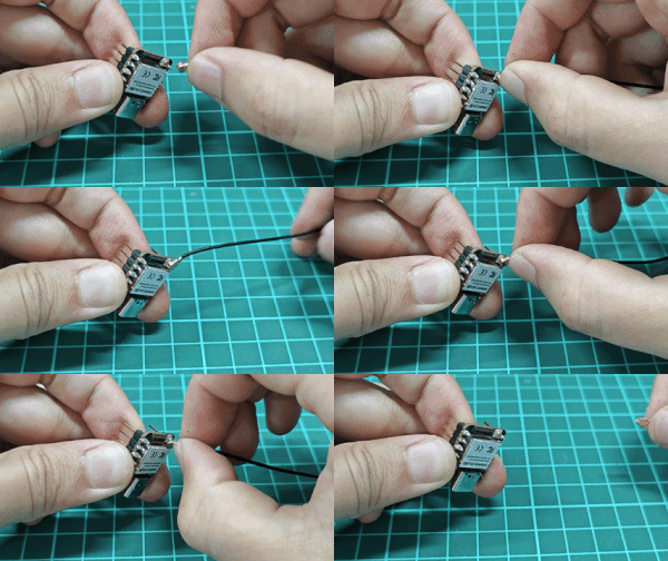
在 XIAO ESP32S3 正面左下角,有一个独立的 “WiFi/BT Antenna Connector”。为了获得更好的 WiFi/Bluetooth 信号,你需要取出包装内附带的天线,并将其安装到该连接器上。
天线的安装有一个小技巧,如果直接用力向下按,你会发现非常难按下去,而且手指会很疼!正确的安装方式是先将天线连接器的一侧卡入连接器块中,然后再轻轻按下另一侧,天线就能安装到位。
扩展板安装(适用于 Sense)
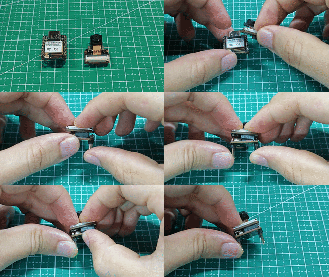
扩展板的安装非常简单,你只需要将扩展板上的连接器与 XIAO ESP32S3 上的 B2B 连接器对齐,用力按下,听到 “咔哒” 一声,安装就完成了。
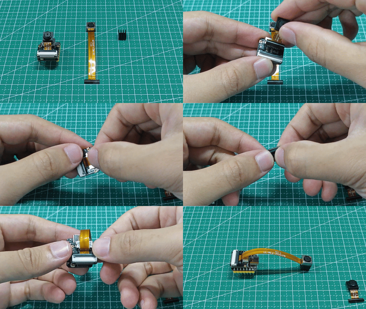
我们现在上架了一款全新、与 XIAO ESP32S3 Sense 完全兼容的高性能摄像头 OV5640,如果你购买它,就可以更换原有摄像头来使用。
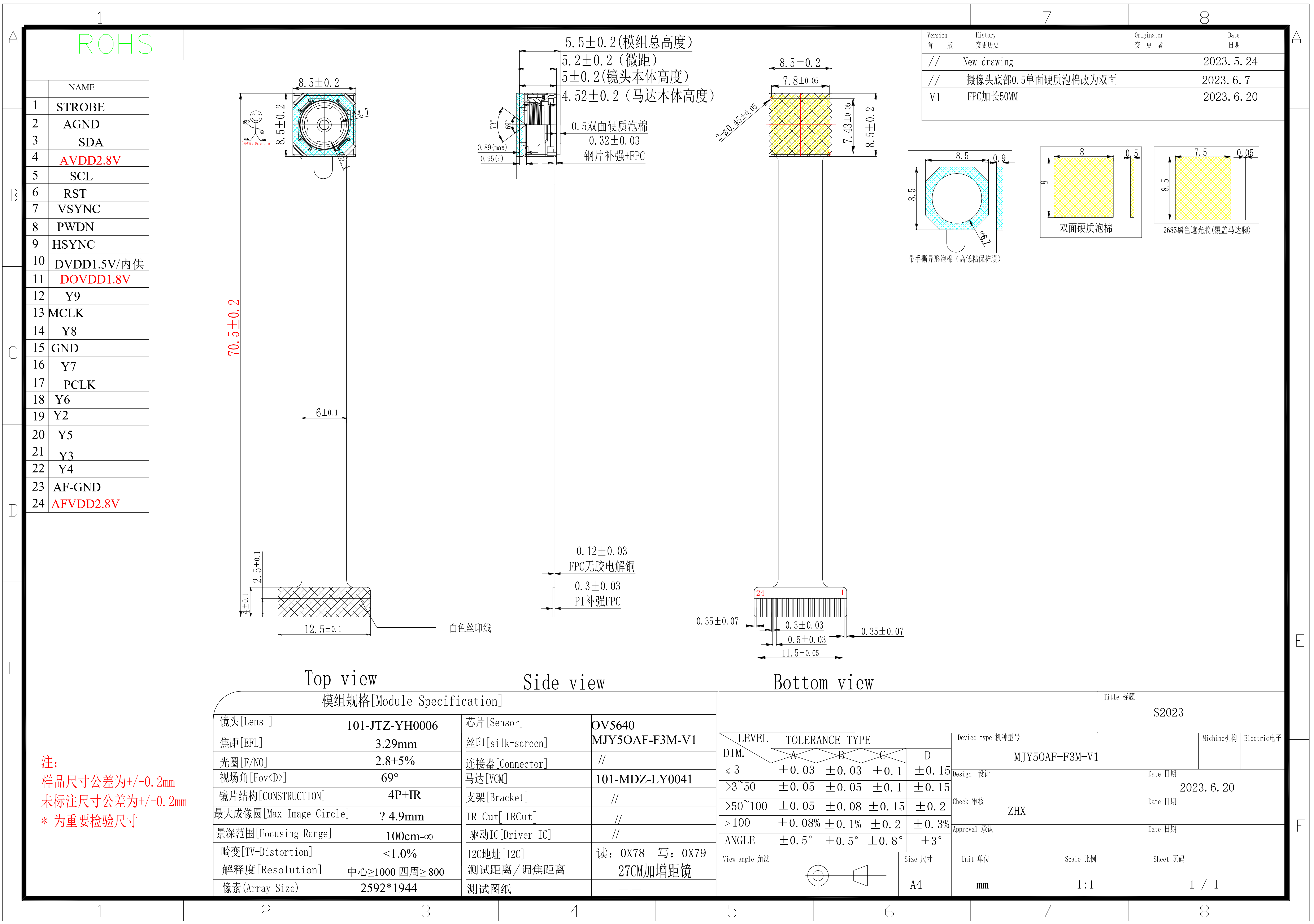
如果你需要了解 OV5640 的详细参数信息,可以参考下表。
Wiki 中所有关于摄像头的程序同时兼容 OV5640 和 OV2640 摄像头。
准备 microSD 卡
XIAO ESP32S3 Sense 支持最大 32GB 的 microSD 卡,因此如果你准备为 XIAO 购买 microSD 卡,请参考这一规格。同时,在使用 microSD 卡前,请将其格式化为 FAT32 格式。
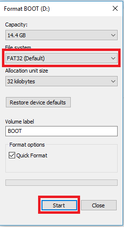
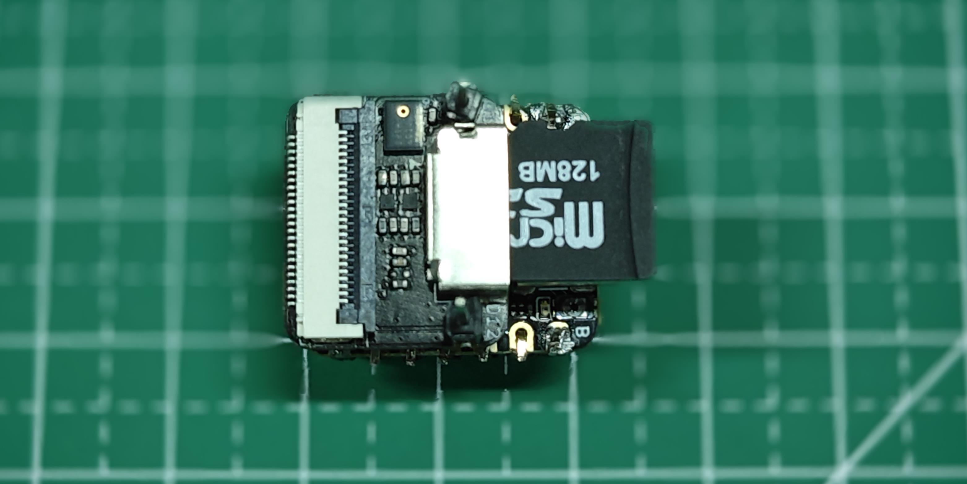
格式化完成后,你可以将 microSD 卡插入 microSD 卡槽。请注意插入方向,带有金手指的一面应朝内。
扩展板摄像头卡槽电路设计
XIAO ESP32S3 Sense 的摄像头卡槽占用了 ESP32-S3 的 14 个 GPIO,引脚占用详情如下表所示。
| ESP32-S3 GPIO | Camera | ESP32-S3 GPIO | Camera |
|---|---|---|---|
| GPIO10 | XMCLK | GPIO11 | DVP_Y8 |
| GPIO12 | DVP_Y7 | GPIO13 | DVP_PCLK |
| GPIO14 | DVP_Y6 | GPIO15 | DVP_Y2 |
| GPIO16 | DVP_Y5 | GPIO17 | DVP_Y3 |
| GPIO18 | DVP_Y4 | GPIO38 | DVP_VSYNC |
| GPIO39 | CAM_SCL | GPIO40 | CAM_SDA |
| GPIO47 | DVP_HREF | GPIO48 | DVP_Y9 |
打开 PSRAM 选项
ESP32 的 PSRAM 指的是 ESP32 芯片上的外部 PSRAM(Pseudo Static Random Access Memory,伪静态随机存取存储器),它提供了额外的内存空间,用于增加 ESP32 系统可用内存。在 ESP32 系统中,PSRAM 主要有以下用途:
-
扩展可用 RAM:ESP32 的内置 RAM 是有限的,尤其是对于一些需要大量内存的应用,如图像处理、音频处理等,内置 RAM 可能不够用。通过使用 PSRAM,可以扩展 ESP32 的可用 RAM,以满足这些应用的需求。
-
加速内存访问:由于 PSRAM 是外部存储器,其访问速度比内部 RAM 慢一些,但可以作为缓存或临时存储来加速内存访问和数据处理。
-
存储缓冲区:对于需要大容量缓冲区的应用,如网络缓冲区、音频缓冲区等,PSRAM 可以提供足够的存储空间,避免内存不足的情况。
对于本教程的内容,你需要在 Arduino IDE 中打开 PSRAM 功能,以确保摄像头能够正常工作。
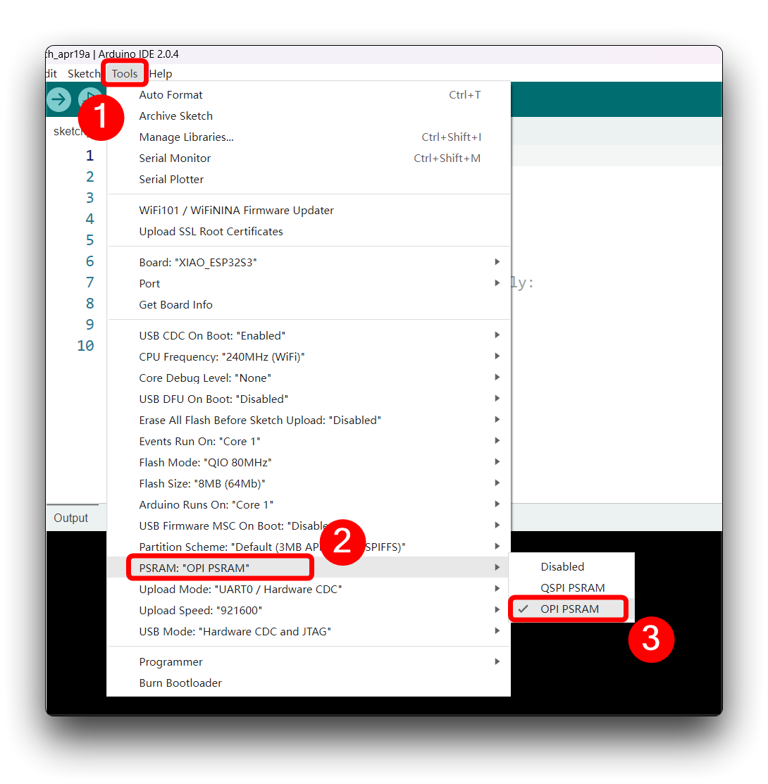
摄像头库概览
在开始之前,我们建议你先阅读本章,了解常用的摄像头功能。这样你就可以使用这些功能来完成自己的项目开发,或者更容易读懂程序。
第一部分:esp_camera.h
- 摄像头初始化的配置结构体。
下面是一个配置示例,只需根据实际引脚情况进行填写即可。
static camera_config_t camera_example_config = {
        .pin_pwdn       = PWDN_GPIO_NUM,
        .pin_reset      = RESET_GPIO_NUM,
        .pin_xclk       = XCLK_GPIO_NUM,
        .pin_sccb_sda   = SIOD_GPIO_NUM,
        .pin_sccb_scl   = SIOC_GPIO_NUM,
        .pin_d7         = Y9_GPIO_NUM,
        .pin_d6         = Y8_GPIO_NUM,
        .pin_d5         = Y7_GPIO_NUM,
        .pin_d4         = Y6_GPIO_NUM,
        .pin_d3         = Y5_GPIO_NUM,
        .pin_d2         = Y4_GPIO_NUM,
        .pin_d1         = Y3_GPIO_NUM,
        .pin_d0         = Y2_GPIO_NUM,
        .pin_vsync      = VSYNC_GPIO_NUM,
        .pin_href       = HREF_GPIO_NUM,
        .pin_pclk       = PCLK_GPIO_NUM,

        .xclk_freq_hz   = 20000000, // The clock frequency of the image sensor
        .fb_location = CAMERA_FB_IN_PSRAM; // Set the frame buffer storage location
        .pixel_format   = PIXFORMAT_JPEG, // The pixel format of the image: PIXFORMAT_ + YUV422|GRAYSCALE|RGB565|JPEG
        .frame_size     = FRAMESIZE_UXGA, // The resolution size of the image: FRAMESIZE_ + QVGA|CIF|VGA|SVGA|XGA|SXGA|UXGA
        .jpeg_quality   = 12, // The quality of the JPEG image, ranging from 0 to 63.
        .fb_count       = 2, // The number of frame buffers to use.
        .grab_mode      = CAMERA_GRAB_WHEN_EMPTY //  The image capture mode.
    };
- 初始化摄像头驱动。
在按照上述格式配置好 camera_example_config 之后,我们需要使用此函数来初始化摄像头驱动。
esp_err_t esp_camera_init(const camera_config_t* config);
-
输入参数:摄像头配置参数
-
输出:成功时返回 ESP_OK
目前该函数只能被调用一次,且没有办法对该模块进行反初始化。
- 获取帧缓冲区指针。
camera_fb_t* esp_camera_fb_get();
摄像头帧缓冲区的数据结构:
typedef struct {
    uint8_t * buf;              /*!< Pointer to the pixel data */
    size_t len;                 /*!< Length of the buffer in bytes */
    size_t width;               /*!< Width of the buffer in pixels */
    size_t height;              /*!< Height of the buffer in pixels */
    pixformat_t format;         /*!< Format of the pixel data */
    struct timeval timestamp;   /*!< Timestamp since boot of the first DMA buffer of the frame */
} camera_fb_t;
- 将帧缓冲区返回以便再次复用。
void esp_camera_fb_return(camera_fb_t * fb);
- 输入参数: 指向帧缓冲区的指针
- 获取指向图像传感器控制结构的指针。
sensor_t * esp_camera_sensor_get();
- 输出: 指向传感器的指针
- 将相机设置保存到非易失性存储(NVS)。
esp_err_t esp_camera_save_to_nvs(const char *key);
- 输入参数: 相机设置的唯一 NVS 键名
- 从非易失性存储(NVS)加载相机设置。
esp_err_t esp_camera_load_from_nvs(const char *key);
- 输入参数: 相机设置的唯一 NVS 键名
第二部分: img_converters.h
- 将图像缓冲区转换为 JPEG。
bool fmt2jpg_cb(uint8_t *src, size_t src_len, uint16_t width, uint16_t height, pixformat_t format, uint8_t quality, jpg_out_cb cb, void * arg);
-
输入参数:
- src: RGB565、RGB888、YUYV 或 GRAYSCALE 格式的源缓冲区
- src_len: 源缓冲区的字节长度
- width: 源图像的像素宽度
- height: 源图像的像素高度
- format: 源图像的格式
- quality: 生成图像的 JPEG 质量
- cp: 用于写入输出 JPEG 字节的回调函数
- arg: 传递给回调函数的指针
-
输出: 成功时为 true
- 将相机帧缓冲区转换为 JPEG。
bool frame2jpg_cb(camera_fb_t * fb, uint8_t quality, jpg_out_cb cb, void * arg);
-
输入参数:
- fb: 源相机帧缓冲区
- quality: 生成图像的 JPEG 质量
- cp: 用于写入输出 JPEG 字节的回调函数
- arg: 传递给回调函数的指针
-
输出: 成功时为 true
- 将图像缓冲区转换为 JPEG 缓冲区。
bool fmt2jpg(uint8_t *src, size_t src_len, uint16_t width, uint16_t height, pixformat_t format, uint8_t quality, uint8_t ** out, size_t * out_len);
-
输入参数:
- src: RGB565、RGB888、YUYV 或 GRAYSCALE 格式的源缓冲区
- src_len: 源缓冲区的字节长度
- width: 源图像的像素宽度
- height: 源图像的像素高度
- format: 源图像的格式
- quality: 生成图像的 JPEG 质量
- out: 将填充为生成缓冲区地址的指针。使用完成后你必须释放该指针。
- out_len: 将填充为输出缓冲区长度的指针
-
输出: 成功时为 true
- 将相机帧缓冲区转换为 JPEG 缓冲区。
bool frame2jpg(camera_fb_t * fb, uint8_t quality, uint8_t ** out, size_t * out_len);
-
输入参数:
- fb: 源相机帧缓冲区
- quality: 生成图像的 JPEG 质量
- out: 将填充为生成缓冲区地址的指针
- out_len: 将填充为输出缓冲区长度的指针
-
输出: 成功时为 true
- 将图像缓冲区转换为 BMP 缓冲区。
bool fmt2bmp(uint8_t *src, size_t src_len, uint16_t width, uint16_t height, pixformat_t format, uint8_t ** out, size_t * out_len);
-
输入参数:
- src: RGB565、RGB888、YUYV 或 GRAYSCALE 格式的源缓冲区
- src_len: 源缓冲区的字节长度
- width: 源图像的像素宽度
- height: 源图像的像素高度
- format: 源图像的格式
- quality: 生成图像的 JPEG 质量
- out: 将填充为生成缓冲区地址的指针。
- out_len: 将填充为输出缓冲区长度的指针
-
输出: 成功时为 true
- 将相机帧缓冲区转换为 BMP 缓冲区。
bool frame2bmp(camera_fb_t * fb, uint8_t ** out, size_t * out_len);
-
输入参数:
- fb: 源相机帧缓冲区
- quality: 生成图像的 JPEG 质量
- cp: 用于写入输出 JPEG 字节的回调函数
- arg: 传递给回调函数的指针
-
输出: 成功时为 true
第三部分: app_httpd.cpp
本库介绍的这一部分基于“创建一个视频保存终端——基于 WebServer”章节。该库主要用于为 Web 服务器执行图像采集和人脸识别功能。它并未直接包含在 ESP 的板载包中。
- 人脸识别功能。
static int run_face_recognition(fb_data_t *fb, std::list<dl::detect::result_t> *results)
- 输入参数:
- fb: 指向表示包含图像数据的帧缓冲区结构体的指针。
- results: 指向检测到的人脸结果列表的指针。
- 处理 BMP 图像文件的 HTTP 请求。
static esp_err_t bmp_handler(httpd_req_t *req)
- 输入参数: 指向表示 HTTP 请求的结构体的指针。
- 以流式方式对 JPEG 图像数据进行编码。
static size_t jpg_encode_stream(void *arg, size_t index, const void *data, size_t len)
- 输入参数:
- arg: 传递给函数的用户自定义参数指针。
- index: 表示当前在图像数据中的位置索引值。
- data: 指向包含待编码图像数据的缓冲区的指针。
- len: 数据缓冲区的长度。
- 处理来自相机的图像捕获和流式传输的 HTTP 请求。
static esp_err_t capture_handler(httpd_req_t *req)
- 输入参数: 指向表示 HTTP 请求的结构体的指针。
- 处理来自相机的视频流 HTTP 请求。
static esp_err_t stream_handler(httpd_req_t *req)
- 输入参数: 指向表示 HTTP 请求的结构体的指针。
- 初始化并启动一个通过 HTTP 捕获和传输视频的相机服务器。
void startCameraServer()
使用相机拍照
接下来我们从相机最基础的用法开始,例如,我们将首先使用相机完成图像采集。第一个项目中我们会使用 microSD 卡,该程序的主要任务是每分钟获取一次相机画面,然后将画面保存到 microSD 卡中。
在开始之前,请像我一样先安装好 microSD 卡和相机。
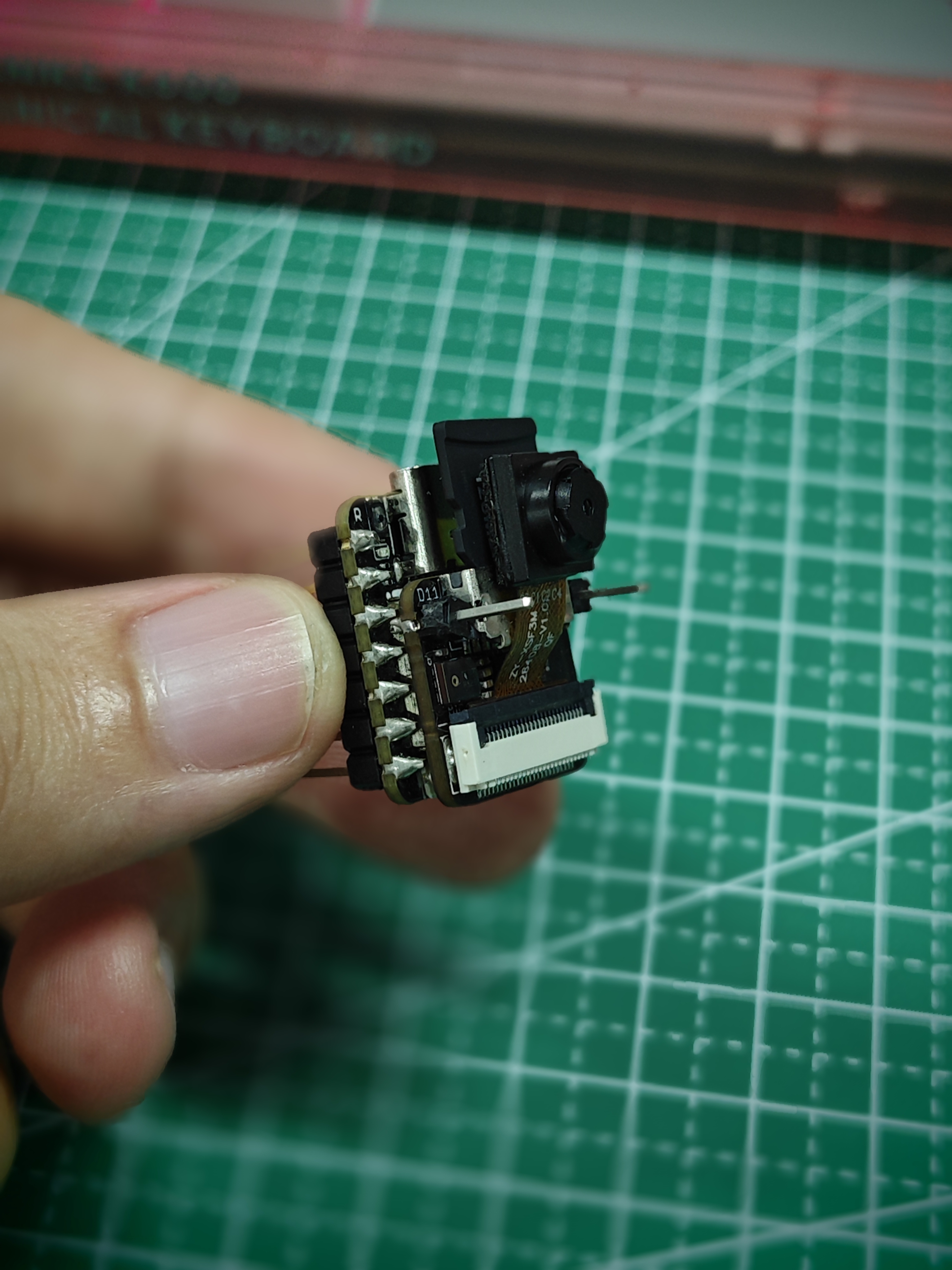
你可以在下面这个链接中找到完整的程序代码和所需的依赖文件。
下面是本项目的 Arduino 程序。
#include "esp_camera.h"
#include "FS.h"
#include "SD.h"
#include "SPI.h"

#define CAMERA_MODEL_XIAO_ESP32S3 // Has PSRAM

#include "camera_pins.h"
#include "ESP32_OV5640_AF.h"   // OV5640 auto-focus library (github.com/0015/ESP32-OV5640-AF)

OV5640 ov5640 = OV5640();

#define OV5640_AF_FOCUS_FRAMESIZE FRAMESIZE_SXGA // AF focusing requires >=1280x1024
#define OV5640_FOCUS_TIMEOUT_MS  8000

unsigned long lastCaptureTime = 0; // Last shooting time
int imageCount = 1;                // File Counter
bool camera_sign = false;          // Check camera status
bool sd_sign = false;              // Check sd status

// Save pictures to SD card
void photo_save(const char * fileName) {
  // Take a photo
  camera_fb_t *fb = esp_camera_fb_get();
  if (!fb) {
    Serial.println("Failed to get camera frame buffer");
    return;
  }
  // Save photo to file
  writeFile(SD, fileName, fb->buf, fb->len);

  // Release image buffer
  esp_camera_fb_return(fb);

  Serial.println("Photo saved to file");
}

// SD card write file
void writeFile(fs::FS &fs, const char * path, uint8_t * data, size_t len){
    Serial.printf("Writing file: %s\r\n", path);

    File file = fs.open(path, FILE_WRITE);
    if(!file){
        Serial.println("Failed to open file for writing");
        return;
    }
    if(file.write(data, len) == len){
        Serial.println("File written");
    } else {
        Serial.println("Write failed");
    }
    file.close();
}

// Wait for the OV5640 continuous auto-focus to settle (FW_STATUS == 0x10 FOCUSED)
bool waitForOv5640Focus() {
  const uint32_t started = millis();
  uint8_t status = 0;
  while (millis() - started < OV5640_FOCUS_TIMEOUT_MS) {
    status = ov5640.getFWStatus();
    if (status == 0x10) {
      Serial.printf("OV5640 focus settled: FW_STATUS=0x%02X\n", status);
      return true;
    }
    delay(100);
  }
  Serial.printf("ERROR: OV5640 focus not settled within %u ms; last FW_STATUS=0x%02X\n",
                OV5640_FOCUS_TIMEOUT_MS, status);
  return false;
}

void setup() {
  Serial.begin(115200);
  while(!Serial); // When the serial monitor is turned on, the program starts to execute

  camera_config_t config;
  config.ledc_channel = LEDC_CHANNEL_0;
  config.ledc_timer = LEDC_TIMER_0;
  config.pin_d0 = Y2_GPIO_NUM;
  config.pin_d1 = Y3_GPIO_NUM;
  config.pin_d2 = Y4_GPIO_NUM;
  config.pin_d3 = Y5_GPIO_NUM;
  config.pin_d4 = Y6_GPIO_NUM;
  config.pin_d5 = Y7_GPIO_NUM;
  config.pin_d6 = Y8_GPIO_NUM;
  config.pin_d7 = Y9_GPIO_NUM;
  config.pin_xclk = XCLK_GPIO_NUM;
  config.pin_pclk = PCLK_GPIO_NUM;
  config.pin_vsync = VSYNC_GPIO_NUM;
  config.pin_href = HREF_GPIO_NUM;
  config.pin_sscb_sda = SIOD_GPIO_NUM;
  config.pin_sscb_scl = SIOC_GPIO_NUM;
  config.pin_pwdn = PWDN_GPIO_NUM;
  config.pin_reset = RESET_GPIO_NUM;
  config.xclk_freq_hz = 20000000;
  config.frame_size = FRAMESIZE_UXGA;
  config.pixel_format = PIXFORMAT_JPEG; // for streaming
  config.grab_mode = CAMERA_GRAB_WHEN_EMPTY;
  config.fb_location = CAMERA_FB_IN_PSRAM;
  config.jpeg_quality = 12;
  config.fb_count = 1;

  // if PSRAM IC present, init with UXGA resolution and higher JPEG quality
  //                      for larger pre-allocated frame buffer.
  if(config.pixel_format == PIXFORMAT_JPEG){
    if(psramFound()){
      config.jpeg_quality = 10;
      config.fb_count = 2;
      config.grab_mode = CAMERA_GRAB_LATEST;
    } else {
      // Limit the frame size when PSRAM is not available
      config.frame_size = FRAMESIZE_SVGA;
      config.fb_location = CAMERA_FB_IN_DRAM;
    }
  } else {
    // Best option for face detection/recognition
    config.frame_size = FRAMESIZE_240X240;
#if CONFIG_IDF_TARGET_ESP32S3
    config.fb_count = 2;
#endif
  }

  // camera init
  esp_err_t err = esp_camera_init(&config);
  if (err != ESP_OK) {
    Serial.printf("Camera init failed with error 0x%x", err);
    return;
  }

  camera_sign = true; // Camera initialization check passes

  // --- OV5640 auto-focus init (a key step missing from factory firmware; without it the lens defaults out of focus) ---
  sensor_t *s = esp_camera_sensor_get();
  if (s && s->id.PID == OV5640_PID) {
    Serial.println("OV5640 detected, initializing auto-focus...");
    // Switch to SXGA for focusing (the AF firmware needs >=1280x1024 to evaluate contrast)
    if (s->set_framesize(s, OV5640_AF_FOCUS_FRAMESIZE) != 0) {
      Serial.println("WARN: cannot set SXGA for AF focus, captures will be out of focus");
    } else if (!ov5640.start(s)) {
      Serial.println("WARN: OV5640 CHIPID check failed, AF skipped");
      s->set_framesize(s, config.frame_size); // restore the capture framesize
    } else {
      int r1 = ov5640.focusInit();                       // load focus firmware, 0 = success
      int r2 = (r1 == 0) ? ov5640.autoFocusMode() : -1;  // enable continuous auto-focus
      Serial.printf("  focusInit=%d autoFocusMode=%d\n", r1, r2);
      if (r1 == 0 && r2 == 0 && waitForOv5640Focus()) {
        Serial.println("OV5640 AF ready.");
      } else {
        Serial.println("ERROR: OV5640 AF setup failed; captures will be out of focus.");
      }
      // Restore the capture framesize
      if (s->set_framesize(s, config.frame_size) != 0) {
        Serial.println("WARN: cannot restore capture framesize");
      }
    }
  }

  // Initialize SD card
  if(!SD.begin(21)){
    Serial.println("Card Mount Failed");
    return;
  }
  uint8_t cardType = SD.cardType();

  // Determine if the type of SD card is available
  if(cardType == CARD_NONE){
    Serial.println("No SD card attached");
    return;
  }

  Serial.print("SD Card Type: ");
  if(cardType == CARD_MMC){
    Serial.println("MMC");
  } else if(cardType == CARD_SD){
    Serial.println("SDSC");
  } else if(cardType == CARD_SDHC){
    Serial.println("SDHC");
  } else {
    Serial.println("UNKNOWN");
  }

  sd_sign = true; // sd initialization check passes

  Serial.println("Photos will begin in one minute, please be ready.");
}

void loop() {
  // Camera & SD available, start taking pictures
  if(camera_sign && sd_sign){
    // Get the current time
    unsigned long now = millis();

    //If it has been more than 1 minute since the last shot, take a picture and save it to the SD card
    if ((now - lastCaptureTime) >= 60000) {
      char filename[32];
      sprintf(filename, "/image%d.jpg", imageCount);
      photo_save(filename);
      Serial.printf("Saved picture: %s\r\n", filename);
      Serial.println("Photos will begin in one minute, please be ready.");
      imageCount++;
      lastCaptureTime = now;
    }
  }
}
编译和上传此程序需要另外两个依赖项,请前往 GitHub 并完整下载它们。
请为 XIAO ESP32S3 上传程序,程序上传成功后,请打开串口监视器,将摄像头调整为对准你想要拍摄的物体,等待一分钟,拍摄的照片会被保存到 SD 卡中。接下来,XIAO 将每分钟拍摄一张照片。
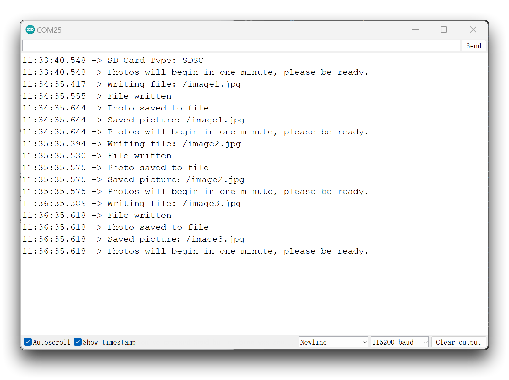
取下 microSD 卡,在读卡器的帮助下,你可以看到保存在卡中的照片。
程序注释
程序从我们需要使用的摄像头和 SD 卡库开始,以及我们为 XIAO ESP32S3 定义的一些引脚依赖文件的导入。
然后为了便于阅读,我们依次定义了两个函数,一个是将拍摄图像保存到 SD 卡中的函数 photo_save(),另一个是写入文件的函数 writeFile()。
// Save pictures to SD card
void photo_save(const char * fileName) {
  // Take a photo
  camera_fb_t *fb = esp_camera_fb_get();
  if (!fb) {
    Serial.println("Failed to get camera frame buffer");
    return;
  }
  // Save photo to file
  writeFile(SD, fileName, fb->buf, fb->len);

  // Release image buffer
  esp_camera_fb_return(fb);

  Serial.println("Photo saved to file");
}
在保存图像到 microSD 卡的函数中,完成了两个主要任务。第一个是获取图片,第二个是调用写入文件的函数。
获取图像可以通过 esp_camera_fb_get() 完成,图像信息将保存在指针 fb 中,然后我们可以将 fb 的 buf 写入 SD 卡。
在 Setup() 函数中,大段程序是在配置摄像头引脚和摄像头初始化,我们可以直接按默认方式应用。如果你对摄像头的像素或画质有要求,可以根据 Camera Library Overview 章节中描述的函数来调整其中的数值。
在 loop() 函数中最后要做的事情,是控制每分钟拍摄一次照片,并按照递增的编号作为拍摄照片的文件名后缀。
if(camera_sign && sd_sign){
    // Get the current time
    unsigned long now = millis();

    //If it has been more than 1 minute since the last shot, take a picture and save it to the SD card
    if ((now - lastCaptureTime) >= 60000) {
      char filename[32];
      sprintf(filename, "/image%d.jpg", imageCount);
      photo_save(filename);
      Serial.printf("Saved picture:%s\n", filename);
      Serial.println("Photos will begin in one minute, please be ready.");
      imageCount++;
      lastCaptureTime = now;
    }
  }
在执行 loop() 之前,我们配置了两个标志检查 camera_sign 和 sd_sign。这可以确保在 Setup() 中成功执行摄像头和 SD 卡检查之后,才会运行拍摄和保存图片的任务。
项目一:制作一台手持相机
接下来,我们利用上述理论知识来打造一个超小型拍照神器。该项目的最终效果是:实时摄像头画面显示在 Seeed Studio Round Display for XIAO 上,当你锁定想要拍摄的物体时,触摸屏幕即可拍照并记录到 microSD 卡中。
前期准备
在开始这个项目之前,你需要提前准备以下硬件。
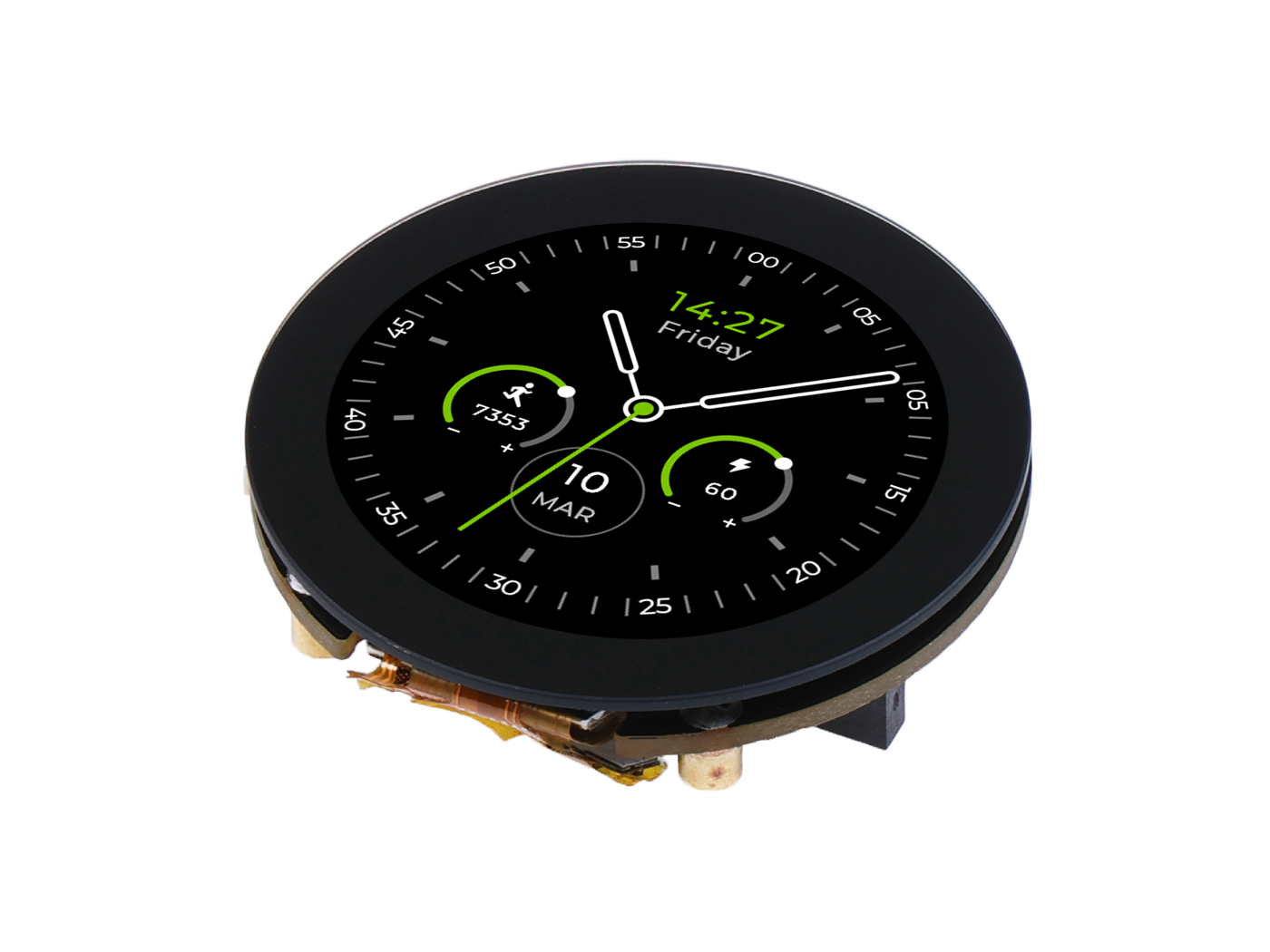
由于本项目将使用 Round Display for XIAO,请在运行本项目的示例程序之前,阅读 显示扩展板的 Wiki 环境配置 的内容,安装必要的库并配置好 TFT 环境。
由于 XIAO EPS32S3 Sense 设计了三个上拉电阻 R4~R6 连接到 SD 卡槽,而圆形显示屏上也有上拉电阻,当两块板同时使用时,两个 SD 卡槽会发生冲突。解决这个问题有两种方法:
- 方案一 — 无需硬件改动(本项目示例代码采用此方案):保持 J3 完好无损,并使用 XIAO ESP32S3 Sense 自带的 microSD 卡槽。正如 工程师 Mjrovai 所演示的,这在软件层面是可行的——下面的代码使用
SD_CS_PIN 21(Sense 读卡器)来初始化 SD 卡。详情请参考 他的实现方法和步骤。 - 方案二 — 切断 J3 并使用 Round Display 卡槽:切断 XIAO ESP32S3 Sense 扩展板上的 J3。断开 J3 后,XIAO ESP32S3 Sense 上的 SD 卡槽将不再工作,因此你需要将 microSD 卡插入 Round Display 上的 SD 卡槽,并将代码中的
SD_CS_PIN从21改为D2。
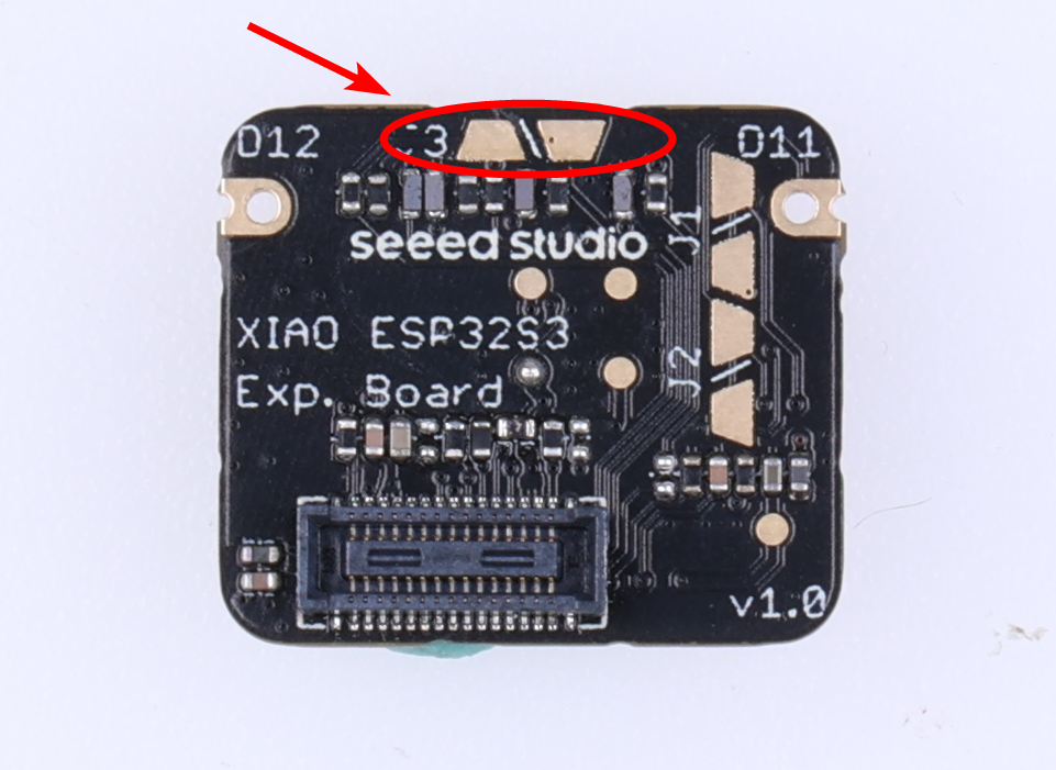
如果你选择方案二,我们建议你先取下摄像头模组,以避免在用刀片切断 J3 连接时刮伤摄像头。
接下来,请依次安装 microSD 卡、XIAO ESP32S3 Sense 和 Round Display。
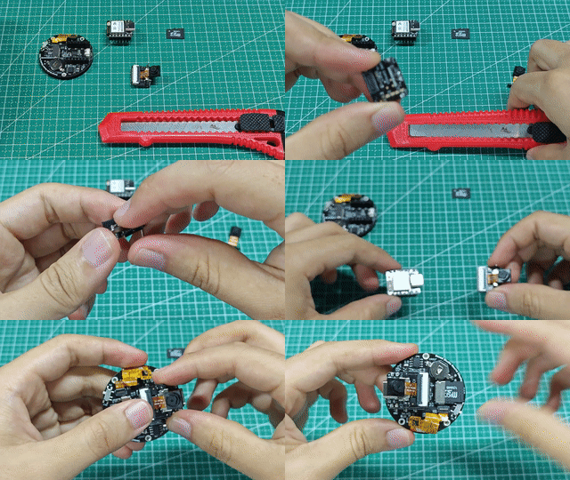
具体操作
你可以在下面这个链接中找到完整的程序代码和所需的依赖文件。
下面是本项目的 Arduino 程序。
/*
 * This code was adapted from the original, developed by Seeed Studio:
 * https://wiki.seeedstudio.com/xiao_esp32s3_camera_usage/#project-i-making-a-handheld-camera
 *
 * Important changes:
 *  - It is not necessary to to cut off J3 on the XIAO ESP32S3 Sense expansion board.
 *  It is possible to use the XIAO's SD Card Reader. For that you need use SD_CS_PIN as 21.
 *
 * - The camera buffer data should be captured as RGB565 (raw image) with a 240x240 frame size
 * to be displayed on the round display. This raw image should be converted to jpeg before save
 * in the SD card. This can be done with the line:
 * bool ok = frame2jpg(fb, 12, &out_buf, &out_len);
 *
 * - The XCLK_FREQ_HZ should be reduced from 20KHz to 10KHz in order to prevent
 * the message "no EV-VSYNC-OVF message" that appears on Serial Monitor (probably due the time
 * added for JPEG conversion.
 *
 * Adapted by MRovai @02June23
 *
 * Generic OV5640 auto-focus patch (only applies to the OV5640; fixed-focus modules
 * such as the OV3660/NT99141 are skipped automatically):
 *  - After esp_camera_init, run focusInit / autoFocusMode only when PID == OV5640_PID
 *  - In RGB565 mode do not switch to SXGA (it would overflow the fb buffer);
 *    rely on the OV5640's internal full-size image for focus evaluation
*/

#include <Arduino.h>
#include <TFT_eSPI.h>
#include <SPI.h>
#include "esp_camera.h"
#include "ESP32_OV5640_AF.h"   // OV5640 auto-focus library (github.com/0015/ESP32-OV5640-AF), OV5640 only
#include "FS.h"
#include "SD.h"

#define CAMERA_MODEL_XIAO_ESP32S3 // Has PSRAM
#define TOUCH_INT D7

/*
 * NOTE: This sketch keeps J3 intact and uses the microSD card slot on the
 * XIAO ESP32S3 Sense itself (SD_CS_PIN 21), so no hardware change is needed
 * (Mjrovai's software-level method). If you have cut J3 and want to use the
 * Round Display card reader instead, comment out the 21 line and use D2.
 */

#define SD_CS_PIN 21 // ESP32S3 Sense SD Card Reader
//#define SD_CS_PIN D2 // XIAO Round Display SD Card Reader (requires J3 cut)

#include "camera_pins.h"

// Width and height of round display
const int camera_width = 240;
const int camera_height = 240;

// File Counter
int imageCount = 1;
bool camera_sign = false;          // Check camera status
bool sd_sign = false;              // Check sd status

TFT_eSPI tft = TFT_eSPI();

// --- OV5640 AF (OV5640 module only) ---
OV5640 ov5640 = OV5640();
#define OV5640_FOCUS_TIMEOUT_MS 8000

// Wait for the OV5640 continuous auto-focus to settle (FW_STATUS == 0x10 FOCUSED)
bool waitForOv5640Focus() {
  const uint32_t started = millis();
  uint8_t status = 0;
  while (millis() - started < OV5640_FOCUS_TIMEOUT_MS) {
    status = ov5640.getFWStatus();
    if (status == 0x10) {
      Serial.printf("OV5640 focus settled: FW_STATUS=0x%02X\n", status);
      return true;
    }
    delay(100);
  }
  Serial.printf("WARN: OV5640 focus not settled within %u ms; last FW_STATUS=0x%02X\n",
                OV5640_FOCUS_TIMEOUT_MS, status);
  return false;
}

// SD card write file
void writeFile(fs::FS &fs, const char * path, uint8_t * data, size_t len){
    Serial.printf("Writing file: %s\n", path);

    File file = fs.open(path, FILE_WRITE);
    if(!file){
        Serial.println("Failed to open file for writing");
        return;
    }
    if(file.write(data, len) == len){
        Serial.println("File written");
    } else {
        Serial.println("Write failed");
    }
    file.close();
}

bool display_is_pressed(void)
{
    if(digitalRead(TOUCH_INT) != LOW) {
        delay(3);
        if(digitalRead(TOUCH_INT) != LOW)
        return false;
    }
    return true;
}

void setup() {
  Serial.begin(115200);
  delay(300);
  Serial.println();
  Serial.println("==== round_display_take_picture_fix ====");

  // Camera pinout
  camera_config_t config;
  config.ledc_channel = LEDC_CHANNEL_0;
  config.ledc_timer = LEDC_TIMER_0;
  config.pin_d0 = Y2_GPIO_NUM;
  config.pin_d1 = Y3_GPIO_NUM;
  config.pin_d2 = Y4_GPIO_NUM;
  config.pin_d3 = Y5_GPIO_NUM;
  config.pin_d4 = Y6_GPIO_NUM;
  config.pin_d5 = Y7_GPIO_NUM;
  config.pin_d6 = Y8_GPIO_NUM;
  config.pin_d7 = Y9_GPIO_NUM;
  config.pin_xclk = XCLK_GPIO_NUM;
  config.pin_pclk = PCLK_GPIO_NUM;
  config.pin_vsync = VSYNC_GPIO_NUM;
  config.pin_href = HREF_GPIO_NUM;
  config.pin_sscb_sda = SIOD_GPIO_NUM;
  config.pin_sscb_scl = SIOC_GPIO_NUM;
  config.pin_pwdn = PWDN_GPIO_NUM;
  config.pin_reset = RESET_GPIO_NUM;
  config.xclk_freq_hz = 10000000; // Reduced XCLK_FREQ_HZ from 20KHz to 10KHz (no EV-VSYNC-OVF message)
  config.frame_size = FRAMESIZE_240X240;
  config.pixel_format = PIXFORMAT_RGB565;
  config.grab_mode = CAMERA_GRAB_WHEN_EMPTY;
  // RGB565 240x240 uses a single internal-DRAM buffer: TFT_eSPI's SPI DMA can read
  // DRAM directly, while reading from PSRAM crashes pushColors (see the Setup66 + PSRAM issue notes)
  config.fb_location = CAMERA_FB_IN_DRAM;
  config.jpeg_quality = 12;
  config.fb_count = 1;

  // camera init
  esp_err_t err = esp_camera_init(&config);
  if (err != ESP_OK) {
    Serial.printf("Camera init failed with error 0x%x", err);
    return;
  }
  Serial.println("Camera ready");
  camera_sign = true; // Camera initialization check passes

  // --- OV5640 auto-focus init (OV5640 only; fixed-focus modules are skipped) ---
  // A key step missing from factory firmware: esp_camera_init does not set up AF,
  // so the OV5640 defaults to an out-of-focus lens.
  // In RGB565 mode do not switch to SXGA (it would overflow the fb buffer);
  // rely on the OV5640's internal full-size image for focus evaluation.
  sensor_t *s = esp_camera_sensor_get();
  if (s && s->id.PID == OV5640_PID) {
    Serial.println("OV5640 detected, initializing auto-focus...");
    if (!ov5640.start(s)) {
      Serial.println("WARN: OV5640 CHIPID check failed, AF skipped");
    } else {
      int r1 = ov5640.focusInit();                       // load focus firmware, 0 = success
      int r2 = (r1 == 0) ? ov5640.autoFocusMode() : -1;  // enable continuous auto-focus
      Serial.printf("  focusInit=%d autoFocusMode=%d\n", r1, r2);
      if (r1 == 0 && r2 == 0) {
        waitForOv5640Focus();
      } else {
        Serial.println("ERROR: OV5640 AF setup failed; captures will be out of focus.");
      }
    }
  } else {
    Serial.printf("PID=0x%04X (not OV5640), AF skipped - fixed-focus module works as-is.\n",
                  s ? s->id.PID : 0);
  }

  // Display initialization
  tft.init();
  pinMode(TFT_BL, OUTPUT);
  digitalWrite(TFT_BL, HIGH);  // turn on the backlight
  tft.setRotation(1);
  tft.fillScreen(TFT_WHITE);

  // Initialize SD card - Card Reader under the camera (21)
  // Change to D2 for using Display Card Reader
  if(!SD.begin(SD_CS_PIN)){
    Serial.println("Card Mount Failed");
    return;
  }
  uint8_t cardType = SD.cardType();

  // Determine if the type of SD card is available
  if(cardType == CARD_NONE){
    Serial.println("No SD card attached");
    return;
  }

  Serial.print("SD Card Type: ");
  if(cardType == CARD_MMC){
    Serial.println("MMC");
  } else if(cardType == CARD_SD){
    Serial.println("SDSC");
  } else if(cardType == CARD_SDHC){
    Serial.println("SDHC");
  } else {
    Serial.println("UNKNOWN");
  }

  sd_sign = true; // sd initialization check passes
}

void loop() {
  if( sd_sign && camera_sign){

    // Take a photo
    camera_fb_t *fb = esp_camera_fb_get();
    if (!fb) {
      Serial.println("Failed to get camera frame buffer");
      return;
    }

    if(display_is_pressed()){
      Serial.println("display is touched");
      char filename[32];
      sprintf(filename, "/image%d.jpg", imageCount);

      // RGB565 -> JPEG, then save to SD (frame2jpg returns bool: true = success)
      size_t out_len = 0;
      uint8_t* out_buf = NULL;
      bool ok = frame2jpg(fb, 12, &out_buf, &out_len);
      if (ok) {
        // Save photo to file
        writeFile(SD, filename, out_buf, out_len);
        Serial.printf("Saved picture: %s\n", filename);
        imageCount++;
        free(out_buf);
      } else {
        Serial.println("JPEG conversion failed");
      }
    }

    // Draw image on the round display
    uint8_t* buf = fb->buf;
    uint32_t len = fb->len;
    tft.startWrite();
    tft.setAddrWindow(0, 0, camera_width, camera_height);
    tft.pushColors(buf, len);
    tft.endWrite();

    // Release image buffer
    esp_camera_fb_return(fb);

    delay(10);
  }
}
将程序上传到 XIAO ESP32S3 Sense,如果上传成功后屏幕没有点亮,你可能需要按一下 XIAO 上的 Reset 按钮,然后你就会在圆形屏幕上实时看到监控画面。点击屏幕上的任意位置,图像就会被记录并保存到 microSD 卡中。
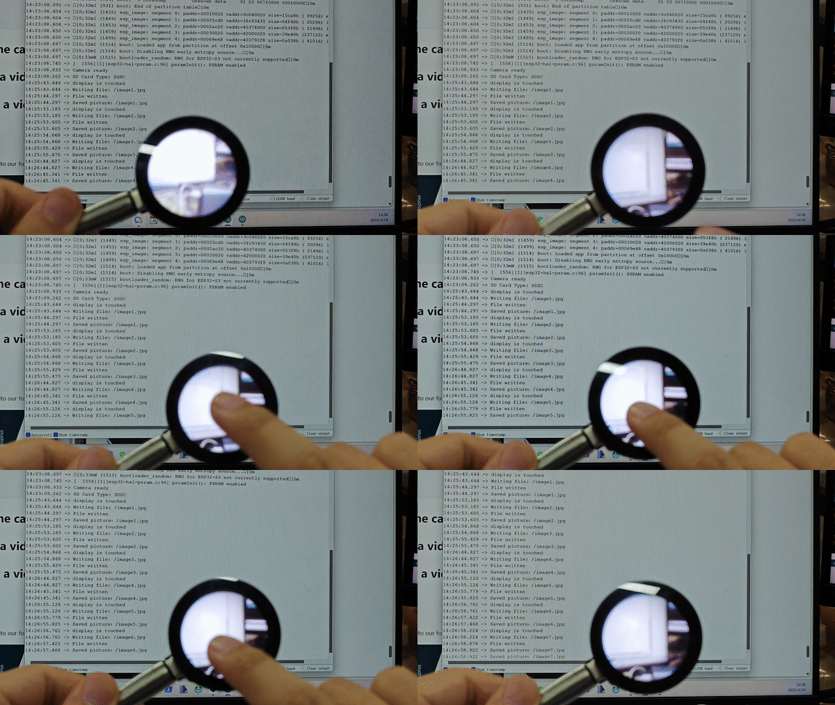
程序注释
摄像头和 microSD 卡的配置是前面的内容,这里不再赘述。关于 microSD 卡的使用,你可以参考 XIAO ESP32S3 Sense file system Wiki 来学习如何使用它。
// Take a photo
camera_fb_t *fb = esp_camera_fb_get();
if (!fb) {
  Serial.println("Failed to get camera frame buffer");
  return;
}

...

// Release image buffer
esp_camera_fb_return(fb);

delay(10);
上述程序是调用摄像头的基本代码块,分为三个部分:屏幕捕获、异常退出以及释放照片缓冲区。
if(display_is_pressed()){
  Serial.println("display is touched");
  char filename[32];
  sprintf(filename, "/image%d.jpg", imageCount);
  // Save photo to file
  writeFile(SD, filename, fb->buf, fb->len);
  Serial.printf("Saved picture:%s\n", filename);
  imageCount++;
}
上述程序用于检查屏幕是否被触摸。如果被触摸,代码会将捕获到的图像保存为 microSD 卡上的一个文件。
// Decode JPEG images
uint8_t* buf = fb->buf;
uint32_t len = fb->len;
tft.startWrite();
tft.setAddrWindow(0, 0, camera_width, camera_height);
tft.pushColors(buf, len);
tft.endWrite();
这部分代码用于在屏幕上显示捕获到的图像。它首先从 camera_fb_t 结构体中获取图像缓冲区及其长度。然后,它设置屏幕以接收图像数据,并使用 pushColors() 函数在屏幕上显示图像。
录制短视频并保存到 microSD 卡
我们不建议在 MCU 上进行视频编码导出,因为当前支持的编码库资源太少,而且操作非常复杂和繁琐。
本示例不涉及视频编码,导出的视频是每帧为 AVI 的 MJPG 组合,因此视频录制效果可能不是特别好和令人满意。本教程的目的是为你提供录制短视频的简单方法和思路,我们也欢迎有更好解决方案的伙伴向我们提交 PR。
在前面的章节中,我们掌握了如何使用摄像头捕获图像。我们知道,单张图像拼接在一起就构成了动态的视频画面。基于这个原理,本章的项目将指导你编写一个程序,每隔 1 分钟录制一段 10 秒的视频,并将其保存在 microSD 卡中。
你可以在下面这个链接中找到完整的程序代码和所需的依赖文件。
下面是本项目的 Arduino 程序。
#include "esp_camera.h"
#include "FS.h"
#include "SD.h"
#include "SPI.h"
#include "esp_timer.h"

#define CAMERA_MODEL_XIAO_ESP32S3 // Has PSRAM

#include "camera_pins.h"

const int SD_PIN_CS = 21;

File videoFile;
bool camera_sign = false;
bool sd_sign = false;
unsigned long lastCaptureTime = 0;
unsigned long captureDuration = 10000; // 10 seconds
int imageCount = 0;

void setup() {
  Serial.begin(115200);
  while(!Serial);

  // Initialize the camera
  camera_config_t config;
  config.ledc_channel = LEDC_CHANNEL_0;
  config.ledc_timer = LEDC_TIMER_0;
  config.pin_d0 = Y2_GPIO_NUM;
  config.pin_d1 = Y3_GPIO_NUM;
  config.pin_d2 = Y4_GPIO_NUM;
  config.pin_d3 = Y5_GPIO_NUM;
  config.pin_d4 = Y6_GPIO_NUM;
  config.pin_d5 = Y7_GPIO_NUM;
  config.pin_d6 = Y8_GPIO_NUM;
  config.pin_d7 = Y9_GPIO_NUM;
  config.pin_xclk = XCLK_GPIO_NUM;
  config.pin_pclk = PCLK_GPIO_NUM;
  config.pin_vsync = VSYNC_GPIO_NUM;
  config.pin_href = HREF_GPIO_NUM;
  config.pin_sscb_sda = SIOD_GPIO_NUM;
  config.pin_sscb_scl = SIOC_GPIO_NUM;
  config.pin_pwdn = PWDN_GPIO_NUM;
  config.pin_reset = RESET_GPIO_NUM;
  config.xclk_freq_hz = 20000000;
  config.pixel_format = PIXFORMAT_JPEG;
  config.frame_size = FRAMESIZE_SVGA;
  config.grab_mode = CAMERA_GRAB_WHEN_EMPTY;
  config.fb_location = CAMERA_FB_IN_PSRAM;
  config.jpeg_quality = 12;
  config.fb_count = 1;

  // camera init
  esp_err_t err = esp_camera_init(&config);
  if (err != ESP_OK) {
    Serial.printf("Camera init failed with error 0x%x", err);
    return;
  }

  camera_sign = true;

  // Initialize the SD card
  if (!SD.begin(SD_PIN_CS)) {
    Serial.println("SD card initialization failed!");
    return;
  }

  uint8_t cardType = SD.cardType();

  // Determine if the type of SD card is available
  if(cardType == CARD_NONE){
    Serial.println("No SD card attached");
    return;
  }

  Serial.print("SD Card Type: ");
  if(cardType == CARD_MMC){
    Serial.println("MMC");
  } else if(cardType == CARD_SD){
    Serial.println("SDSC");
  } else if(cardType == CARD_SDHC){
    Serial.println("SDHC");
  } else {
    Serial.println("UNKNOWN");
  }

  sd_sign = true;

  Serial.println("Video will begin in one minute, please be ready.");
}

void loop() {
  // Camera & SD available, start taking video
  if (camera_sign && sd_sign) {
    // Get the current time
    unsigned long now = millis();

    //If it has been more than 1 minute since the last video capture, start capturing a new video
    if ((now - lastCaptureTime) >= 60000) {
      char filename[32];
      sprintf(filename, "/video%d.avi", imageCount);
      videoFile = SD.open(filename, FILE_WRITE);
      if (!videoFile) {
        Serial.println("Error opening video file!");
        return;
      }
      Serial.printf("Recording video:%s\n", filename);
      lastCaptureTime = now;

      // Start capturing video frames
      while ((millis() - lastCaptureTime) < captureDuration) {
        camera_fb_t *fb = esp_camera_fb_get();
        if (!fb) {
          Serial.println("Error getting framebuffer!");
          break;
        }
        videoFile.write(fb->buf, fb->len);
        esp_camera_fb_return(fb);
      }

      // Close the video file
      videoFile.close();
      Serial.printf("Video saved: %s\n", filename);
      imageCount++;

      Serial.println("Video will begin in one minute, please be ready.");

      // Wait for the remaining time of the minute
      delay(60000 - (millis() - lastCaptureTime));
    }
  }
}
将代码上传到 XIAO ESP32S3 Sense,打开串口监视器,此时请将摄像头位置调整到你想要记录的物体上,一分钟后,XIAO 上的橙色 LED 将开始闪烁,录制开始并保存到 microSD 卡中。
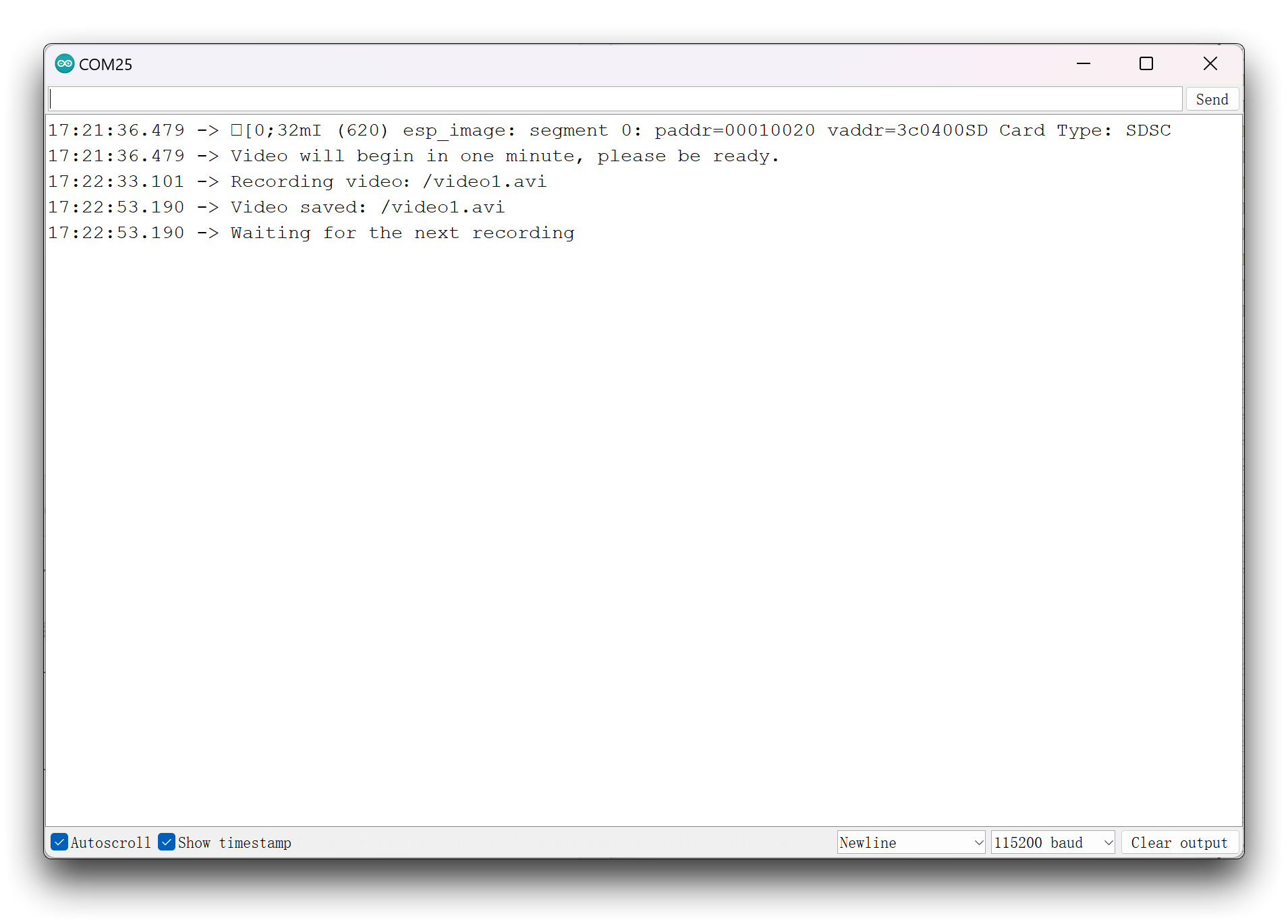
由于程序未涉及编码和帧率等设置,如果录制画面的每一帧都没有变化,视频在打开时可能只会播放一秒钟。
程序注释
录制视频过程中的核心和关键,是在连续 10 秒的时间内持续获取照片流,并持续写入 microSD 卡。
// Start capturing video frames
while ((millis() - lastCaptureTime) < captureDuration) {
  camera_fb_t *fb = esp_camera_fb_get();
  if (!fb) {
    Serial.println("Error getting framebuffer!");
    break;
  }
  videoFile.write(fb->buf, fb->len);
  esp_camera_fb_return(fb);
}
在此基础上,我们在外层再嵌套一层 1 分钟的等待判断,以确保每隔 1 分钟开始一次视频录制。
//If it has been more than 1 minute since the last video capture, start capturing a new video
if ((now - lastCaptureTime) >= 60000) {

  ...

  delay(60000 - (millis() - lastCaptureTime));
}
项目二:视频流
在本教程的最后,让我们展示一个视频流项目。该项目允许你在由 XIAO ESP32S3 Sense 创建的网页上看到实时视频流,并且你可以通过设置一些参数来改变屏幕的显示效果。
你可以在下面这个链接中找到完整的程序代码和所需的依赖文件。
如果你在 Arduino 上使用的是 2.0.x 版本的 esp32 boards 包,请下载:
如果你在 Arduino 上使用 3.0.x 版本的 esp32 boards 包,请下载以下内容:
这是本项目的 Arduino 程序。
#include "esp_camera.h"
#include "ESP32_OV5640_AF.h"   // OV5640 auto-focus library (OV5640 only)
#include <WiFi.h>

//
// WARNING!!! PSRAM IC required for UXGA resolution and high JPEG quality
//            Ensure ESP32 Wrover Module or other board with PSRAM is selected
//            Partial images will be transmitted if image exceeds buffer size
//
//            You must select partition scheme from the board menu that has at least 3MB APP space.
//            Face Recognition is DISABLED for ESP32 and ESP32-S2, because it takes up from 15
//            seconds to process single frame. Face Detection is ENABLED if PSRAM is enabled as well

// ===================
// Select camera model
// ===================
#define CAMERA_MODEL_XIAO_ESP32S3 // Has PSRAM
#include "camera_pins.h"

// ===========================
// Enter your WiFi credentials
// ===========================
const char *ssid = "**********";
const char *password = "**********";

void startCameraServer();
void setupLedFlash(int pin);

// --- OV5640 AF (OV5640 module only; fixed-focus modules such as the OV3660/NT99141 are skipped automatically) ---
OV5640 ov5640 = OV5640();
#define OV5640_AF_FOCUS_FRAMESIZE FRAMESIZE_SXGA  // AF focus evaluation requires >=1280x1024
#define OV5640_FOCUS_TIMEOUT_MS 8000
bool waitForOv5640Focus() {
  const uint32_t started = millis();
  uint8_t status = 0;
  while (millis() - started < OV5640_FOCUS_TIMEOUT_MS) {
    status = ov5640.getFWStatus();
    if (status == 0x10) { Serial.printf("OV5640 focus settled: FW_STATUS=0x%02X\n", status); return true; }
    delay(100);
  }
  Serial.printf("WARN: OV5640 focus not settled; last FW_STATUS=0x%02X\n", status);
  return false;
}

void setup() {
  Serial.begin(115200);
  Serial.setDebugOutput(true);
  Serial.println();

  camera_config_t config;
  config.ledc_channel = LEDC_CHANNEL_0;
  config.ledc_timer = LEDC_TIMER_0;
  config.pin_d0 = Y2_GPIO_NUM;
  config.pin_d1 = Y3_GPIO_NUM;
  config.pin_d2 = Y4_GPIO_NUM;
  config.pin_d3 = Y5_GPIO_NUM;
  config.pin_d4 = Y6_GPIO_NUM;
  config.pin_d5 = Y7_GPIO_NUM;
  config.pin_d6 = Y8_GPIO_NUM;
  config.pin_d7 = Y9_GPIO_NUM;
  config.pin_xclk = XCLK_GPIO_NUM;
  config.pin_pclk = PCLK_GPIO_NUM;
  config.pin_vsync = VSYNC_GPIO_NUM;
  config.pin_href = HREF_GPIO_NUM;
  config.pin_sccb_sda = SIOD_GPIO_NUM;
  config.pin_sccb_scl = SIOC_GPIO_NUM;
  config.pin_pwdn = PWDN_GPIO_NUM;
  config.pin_reset = RESET_GPIO_NUM;
  config.xclk_freq_hz = 20000000;
  config.frame_size = FRAMESIZE_UXGA;
  config.pixel_format = PIXFORMAT_JPEG;  // for streaming
  //config.pixel_format = PIXFORMAT_RGB565; // for face detection/recognition
  config.grab_mode = CAMERA_GRAB_WHEN_EMPTY;
  config.fb_location = CAMERA_FB_IN_PSRAM;
  config.jpeg_quality = 12;
  config.fb_count = 1;

  // if PSRAM IC present, init with UXGA resolution and higher JPEG quality
  //                      for larger pre-allocated frame buffer.
  if (config.pixel_format == PIXFORMAT_JPEG) {
    if (psramFound()) {
      config.jpeg_quality = 10;
      config.fb_count = 2;
      config.grab_mode = CAMERA_GRAB_LATEST;
    } else {
      // Limit the frame size when PSRAM is not available
      config.frame_size = FRAMESIZE_SVGA;
      config.fb_location = CAMERA_FB_IN_DRAM;
    }
  } else {
    // Best option for face detection/recognition
    config.frame_size = FRAMESIZE_240X240;
#if CONFIG_IDF_TARGET_ESP32S3
    config.fb_count = 2;
#endif
  }

#if defined(CAMERA_MODEL_ESP_EYE)
  pinMode(13, INPUT_PULLUP);
  pinMode(14, INPUT_PULLUP);
#endif

  // camera init
  esp_err_t err = esp_camera_init(&config);
  if (err != ESP_OK) {
    Serial.printf("Camera init failed with error 0x%x", err);
    return;
  }

  sensor_t *s = esp_camera_sensor_get();
  // --- OV5640 Heat Optimization: lower IO drive (0x302C bit[7:6] 11->00) ---
  if (s && s->id.PID == OV5640_PID) {
    s->set_reg(s, 0x302C, 0xC0, 0x00);
  }
  // --- OV5640 auto-focus init (OV5640 only; fixed-focus modules are skipped) ---
  if (s && s->id.PID == OV5640_PID) {
    Serial.println("OV5640 detected, initializing auto-focus...");
    if (s->set_framesize(s, OV5640_AF_FOCUS_FRAMESIZE) == 0 && ov5640.start(s)) {
      int r1 = ov5640.focusInit();
      int r2 = (r1 == 0) ? ov5640.autoFocusMode() : -1;
      Serial.printf("  focusInit=%d autoFocusMode=%d\n", r1, r2);
      if (r1 == 0 && r2 == 0) waitForOv5640Focus();
      s->set_framesize(s, config.frame_size);  // restore the capture framesize
    } else {
      Serial.println("WARN: OV5640 AF setup failed, skipped");
      s->set_framesize(s, config.frame_size);
    }
  }
  // initial sensors are flipped vertically and colors are a bit saturated
  if (s->id.PID == OV3660_PID) {
    s->set_vflip(s, 1);        // flip it back
    s->set_brightness(s, 1);   // up the brightness just a bit
    s->set_saturation(s, -2);  // lower the saturation
  }
  // drop down frame size for higher initial frame rate
  if (config.pixel_format == PIXFORMAT_JPEG) {
    s->set_framesize(s, FRAMESIZE_QVGA);
  }

#if defined(CAMERA_MODEL_M5STACK_WIDE) || defined(CAMERA_MODEL_M5STACK_ESP32CAM)
  s->set_vflip(s, 1);
  s->set_hmirror(s, 1);
#endif

#if defined(CAMERA_MODEL_ESP32S3_EYE)
  s->set_vflip(s, 1);
#endif

// Setup LED FLash if LED pin is defined in camera_pins.h
#if defined(LED_GPIO_NUM)
  setupLedFlash(LED_GPIO_NUM);
#endif

  WiFi.begin(ssid, password);
  WiFi.setSleep(false);

  while (WiFi.status() != WL_CONNECTED) {
    delay(500);
    Serial.print(".");
  }
  Serial.println("");
  Serial.println("WiFi connected");

  startCameraServer();

  Serial.print("Camera Ready! Use 'http://");
  Serial.print(WiFi.localIP());
  Serial.println("' to connect");
}

void loop() {
  // Do nothing. Everything is done in another task by the web server
  delay(10000);
}
在上传程序之前,你需要将代码中的 WiFi 名称和密码修改为你自己的。上传程序后,如果 XIAO ESP32C3 成功连接到你的 WiFi,它的 IP 地址将会被打印出来。
XIAO ESP32S3 在长时间推流过程中会变得非常烫——请注意防止烫伤。为了降低温度,请应用下面的 OV5640 Heat Optimization 补丁。
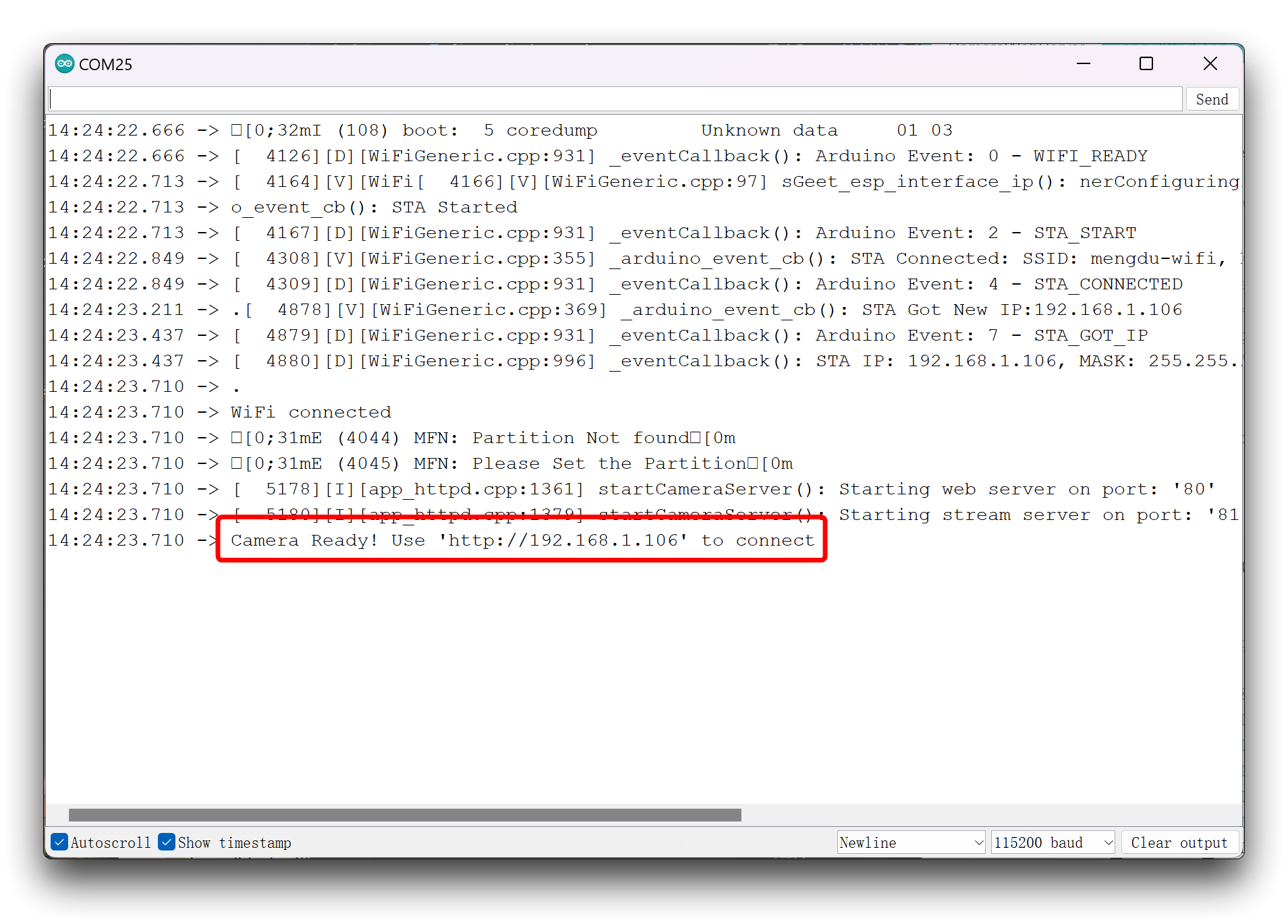
如上图所示,如果你打开了调试信息输出,那么你可能会在串口监视器中看到一些芯片内核的调试信息。例如 [0;31mE (2947) MFN: Partition Not found[0m,请不要担心,它不会影响程序的运行。
请打开你的浏览器,我们推荐 Edge 或 Google Chrome,然后输入该 IP 地址,你就会看到视频的配置页面。
请注意,你使用浏览器的设备需要和 XIAO 处于同一局域网中。
在配置好你想要设置的视频流规格后,点击左侧工具栏底部的 Start Stream,你就可以看到摄像头的实时画面。
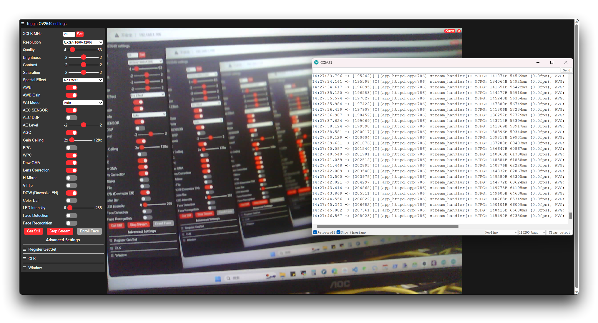
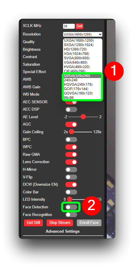
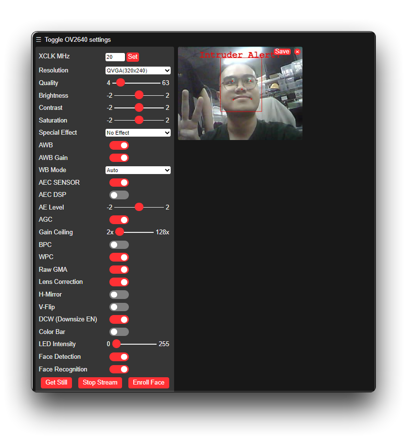
幸运的是,ESP32 官方也在程序中加入了人脸识别功能。你可以通过在降低画质的前提下打开人脸识别的按钮开关来体验这一特性。
出于性能原因,画面质量不能高于 CIF,否则当你打开人脸识别开关时,网页会弹出错误。
哦,我的大脸被圈出来了。
OV5640 自动对焦
硬件准备
| 适用于 XIAO ESP32S3 Sense 的 OV5640 摄像头 |
|---|
 |
软件准备
方法 1
特别感谢 @Eric 提供开源代码
代码示例
#include "esp_camera.h"
#include <WiFi.h>
#include "ESP32_OV5640_AF.h"

#define CAMERA_MODEL_XIAO_ESP32S3 // Has PSRAM

#include "camera_pins.h"

const char* ssid = "";
const char* password = "";

void startCameraServer();
void setupLedFlash(int pin);
OV5640 ov5640 = OV5640();

void setup() {
  Serial.begin(115200);
  while(!Serial);
  Serial.setDebugOutput(true);
  Serial.println();

  camera_config_t config;
  config.ledc_channel = LEDC_CHANNEL_0;
  config.ledc_timer = LEDC_TIMER_0;
  config.pin_d0 = Y2_GPIO_NUM;
  config.pin_d1 = Y3_GPIO_NUM;
  config.pin_d2 = Y4_GPIO_NUM;
  config.pin_d3 = Y5_GPIO_NUM;
  config.pin_d4 = Y6_GPIO_NUM;
  config.pin_d5 = Y7_GPIO_NUM;
  config.pin_d6 = Y8_GPIO_NUM;
  config.pin_d7 = Y9_GPIO_NUM;
  config.pin_xclk = XCLK_GPIO_NUM;
  config.pin_pclk = PCLK_GPIO_NUM;
  config.pin_vsync = VSYNC_GPIO_NUM;
  config.pin_href = HREF_GPIO_NUM;
  config.pin_sscb_sda = SIOD_GPIO_NUM;
  config.pin_sscb_scl = SIOC_GPIO_NUM;
  config.pin_pwdn = PWDN_GPIO_NUM;
  config.pin_reset = RESET_GPIO_NUM;
  config.xclk_freq_hz = 20000000;
  config.frame_size = FRAMESIZE_UXGA;
  config.pixel_format = PIXFORMAT_JPEG; // for streaming
  //config.pixel_format = PIXFORMAT_RGB565; // for face detection/recognition
  config.grab_mode = CAMERA_GRAB_WHEN_EMPTY;
  config.fb_location = CAMERA_FB_IN_PSRAM;
  config.jpeg_quality = 12;
  config.fb_count = 1;

  // if PSRAM IC present, init with UXGA resolution and higher JPEG quality
  //                      for larger pre-allocated frame buffer.
  if(config.pixel_format == PIXFORMAT_JPEG){
    if(psramFound()){
      config.jpeg_quality = 10;
      config.fb_count = 2;
      config.grab_mode = CAMERA_GRAB_LATEST;
    } else {
      // Limit the frame size when PSRAM is not available
      config.frame_size = FRAMESIZE_SVGA;
      config.fb_location = CAMERA_FB_IN_DRAM;
    }
  } else {
    // Best option for face detection/recognition
    config.frame_size = FRAMESIZE_240X240;
#if CONFIG_IDF_TARGET_ESP32S3
    config.fb_count = 2;
#endif
  }

  // camera init
  esp_err_t err = esp_camera_init(&config);
  if (err != ESP_OK) {
    Serial.printf("Camera init failed with error 0x%x", err);
    return;
  }

  sensor_t * s = esp_camera_sensor_get();
  // --- OV5640 Heat Optimization: lower IO drive (0x302C bit[7:6] 11->00) ---
  if (s && s->id.PID == OV5640_PID) {
    s->set_reg(s, 0x302C, 0xC0, 0x00);
  }
  ov5640.start(s);

    if (ov5640.focusInit() == 0) {
    Serial.println("OV5640_Focus_Init Successful!");
  }

  if (ov5640.autoFocusMode() == 0) {
    Serial.println("OV5640_Auto_Focus Successful!");
  }

// Setup LED FLash if LED pin is defined in camera_pins.h
#if defined(LED_GPIO_NUM)
  setupLedFlash(LED_GPIO_NUM);
#endif

  WiFi.begin(ssid, password);
  WiFi.setSleep(false);

  while (WiFi.status() != WL_CONNECTED) {
    delay(500);
    Serial.print(".");
  }
  Serial.println("");
  Serial.println("WiFi connected");

  startCameraServer();

  Serial.print("Camera Ready! Use 'http://");
  Serial.print(WiFi.localIP());
  Serial.println("' to connect");
}

void loop() {
  uint8_t rc = ov5640.getFWStatus();
  Serial.printf("FW_STATUS = 0x%x\n", rc);

  if (rc == -1) {
    Serial.println("Check your OV5640");
  } else if (rc == FW_STATUS_S_FOCUSED) {
    Serial.println("Focused!");
  } else if (rc == FW_STATUS_S_FOCUSING) {
    Serial.println("Focusing!");
  }
}
结果示意图
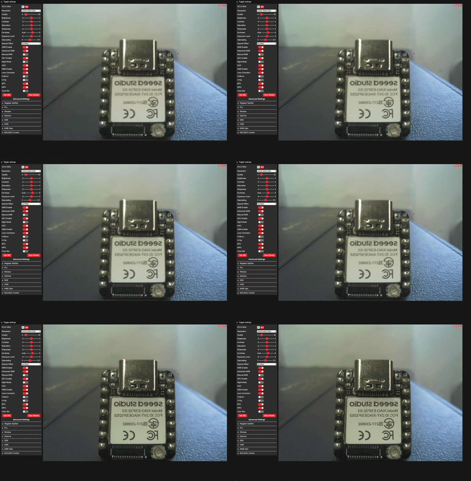
分辨率需要高于 1280*1024 才能看到对焦效果,对焦时屏幕会出现卡顿,需要等待一段时间。
方法 2
分辨率需要高于 1600*1200 才能看到对焦效果,对焦时屏幕会出现卡顿,需要等待一段时间。
下载以下 zip 文件并将其添加到 Arudino 中
- [ZIP] OV5640 Auto
方法 1 和方法 2 中的 OV5640 库不能同时存在
#include "esp_camera.h"
#include <WiFi.h>
#include "ESP32_OV5640_AF.h"

#define CAMERA_MODEL_XIAO_ESP32S3 // Has PSRAM

#include "camera_pins.h"

const char *ssid = "";
const char *password = "";

void startCameraServer();
void setupLedFlash(int pin);
OV5640 ov5640 = OV5640();

void setup() {
  Serial.begin(115200);

  camera_config_t config;
  config.ledc_channel = LEDC_CHANNEL_0;
  config.ledc_timer = LEDC_TIMER_0;
  config.pin_d0 = Y2_GPIO_NUM;
  config.pin_d1 = Y3_GPIO_NUM;
  config.pin_d2 = Y4_GPIO_NUM;
  config.pin_d3 = Y5_GPIO_NUM;
  config.pin_d4 = Y6_GPIO_NUM;
  config.pin_d5 = Y7_GPIO_NUM;
  config.pin_d6 = Y8_GPIO_NUM;
  config.pin_d7 = Y9_GPIO_NUM;
  config.pin_xclk = XCLK_GPIO_NUM;
  config.pin_pclk = PCLK_GPIO_NUM;
  config.pin_vsync = VSYNC_GPIO_NUM;
  config.pin_href = HREF_GPIO_NUM;
  config.pin_sscb_sda = SIOD_GPIO_NUM;
  config.pin_sscb_scl = SIOC_GPIO_NUM;
  config.pin_pwdn = PWDN_GPIO_NUM;
  config.pin_reset = RESET_GPIO_NUM;
  config.xclk_freq_hz = 20000000;
  config.frame_size = FRAMESIZE_UXGA;
  config.pixel_format = PIXFORMAT_JPEG;
  config.grab_mode = CAMERA_GRAB_LATEST;
  config.fb_location = CAMERA_FB_IN_PSRAM;
  config.jpeg_quality = 10;
  config.fb_count = 2;

  if(psramFound()){
    config.jpeg_quality = 10;
    config.fb_count = 2;
    config.grab_mode = CAMERA_GRAB_LATEST;
  } else {
    // Limit the frame size when PSRAM is not available
    config.frame_size = FRAMESIZE_SVGA;
    config.fb_location = CAMERA_FB_IN_DRAM;
  }

  esp_err_t err = esp_camera_init(&config);
  if (err != ESP_OK) {
    Serial.printf("Camera init failed with error 0x%x", err);
    return;
  }

  // auto focus
#if 1
  sensor_t* sensor = esp_camera_sensor_get();
  // --- OV5640 Heat Optimization: lower IO drive (0x302C bit[7:6] 11->00) ---
  if (sensor && sensor->id.PID == OV5640_PID) {
    sensor->set_reg(sensor, 0x302C, 0xC0, 0x00);
  }
  int ret = 0;
  ov5640.start(sensor);

  if (ov5640.focusInit() == 0) {
      Serial.println("OV5640_Focus_Init Successful!");
  } else {
      Serial.println("OV5640_Focus_Init Failed!");
  }

  ret = ov5640.autoFocusMode(false);
  if (ret == 0) {
    Serial.println("OV5640_Auto_Focus Successful!");
  } else {
    Serial.printf("OV5640_Auto_Focus Failed! - [%d]\n", ret);
  }
#endif

  WiFi.begin(ssid, password);
  WiFi.setSleep(false);

  while (WiFi.status() != WL_CONNECTED) {
    delay(500);
    Serial.print(".");
  }
  Serial.println("\nWiFi connected");

  startCameraServer();

  Serial.printf("Camera Ready! Use 'http://%s' to connect\n", WiFi.localIP().toString().c_str());
}

void loop() {
  if (Serial.available()) {
    sensor_t* sensor = esp_camera_sensor_get();
    int ret = 0;

    switch (Serial.read()) {
      case 'b':
        ret = sensor->set_reg(sensor, 0x3022, 0xff, 0x03);
        Serial.printf("begin to auto focus - %d\n", ret);
        break;
      case 's':
        ret = sensor->set_reg(sensor, 0x3022, 0xff, 0x06);
        Serial.printf("focus stop here - %d\n", ret);
        break;
    }
  }

  uint8_t rc = ov5640.getFWStatus();
  Serial.printf("FW_STATUS = 0x%x\n", rc);

  if (rc == -1) {
    Serial.println("Check your OV5640");
  } else if (rc == FW_STATUS_S_FOCUSED) {
    Serial.println("Focused!");
  } else if (rc == FW_STATUS_S_FOCUSING) {
    Serial.println("Focusing!");
  } else {
  }

  delay(1000);
}
推荐使用模式 1,因为它相比模式 2 具有更明显的对焦效果,并且图像更清晰。
OV5640 发热优化
OV5640 模组在长时间运行时会明显发热。本节提供两种降低温度的方法:通过调整软件参数(方法 1),以及通过寄存器配置降低 IO 驱动能力(方法 2)。
方法 1:通过调参降低发热
本 Wiki 中的示例代码针对尽可能好的图像质量进行了调优——在照片示例中使用 UXGA 分辨率(1600×1200)、双缓冲连续取帧,以及 240MHz CPU——因此在长时间运行时板子会明显发热。如果你觉得温度过高,或者并不需要这么高的分辨率,可以通过以下方式降低功耗,其中大多数不会影响单次拍摄的清晰度:
| 杠杆 | 需要更改的内容 | 降温效果 | 会影响图像质量吗? |
|---|---|---|---|
| CPU 频率 | Arduino IDE:Tools → CPU Frequency: 240MHz → 160MHz(或在 setup() 中添加 setCpuFrequencyMhz(160);) | 中等 | 不会(传感器成像和 JPEG 编码在 OV5640 内部完成,与 CPU 无关) |
| 对焦频率 | 将连续自动对焦(autoFocusMode)切换为周期性触发的单次对焦,或延长对焦间隔 | 较小 | 静态场景不变;运动场景重新对焦所需时间更长 |
| 帧抓取方式 | CAMERA_GRAB_LATEST → CAMERA_GRAB_WHEN_EMPTY(相机会填满可用缓冲区,从而减少连续帧处理;这不是按需采集,也不会让传感器进入待机) | 中等 | 你抓取到的帧可能比使用 CAMERA_GRAB_LATEST 时旧几帧;清晰度不受影响 |
| 分辨率 | FRAMESIZE_UXGA (1600×1200) → FRAMESIZE_HD (1280×720) 或 SVGA (800×600) | 较大 | 像素更少,因此放大时细节更少(逐像素清晰度不变) |
| 双缓冲 | 将 fb_count 从 2 改为 1(配合上面的抓取模式更改) | 中等 | 不会 |
性价比最高的组合是使用较低分辨率和单帧缓冲来减少采集与处理开销——也就是在分辨率降低一级的同时,使用
CAMERA_GRAB_WHEN_EMPTY并将fb_count = 1。温度会明显下降,而对单帧抓拍的清晰度几乎没有影响。注意,CAMERA_GRAB_WHEN_EMPTY会填满可用缓冲区;它不提供按需的传感器采集或待机功能。
方法 2:通过降低 IO 驱动能力来降低功耗
本节仅适用于 OV5640 摄像头模组。OV2640 没有这样的寄存器,并且会被下面代码中的 PID 检查自动跳过。
当 OV5640 长时间连续运行时——视频流、实时预览或连续自动对焦——芯片温度可能升至 70°C 以上。这是硬件层面的根本原因,无法通过软件完全消除,只能缓解。
OV5640 为何会发热
- 内部 DVDD 稳压器压降:当 IO 供电(DOVDD)为 2.8V 且使用内部 DVDD 稳压器时,较大的压降本身会耗散大量功率(官方数据手册中有说明)。
- 不正确的上电时序 会引入漏电流并提高静态功耗。
- 数据手册强烈建议在传感器不使用时切断所有电源(包括外部 DVDD),这也从侧面印证了 OV5640 的待机功耗并不理想。
唯一有效的软件手段是降低 IO 引脚的驱动电流,以减少动态功耗。
工作原理 —— 寄存器 0x302C
寄存器 0x302C(在 esp32-camera 源码中命名为 DRIVE_CAPABILITY)用于控制 IO 引脚(D0–D7、PCLK、VSYNC、HREF)的驱动能力。关键字段是 Bit[7:6]:
| Bit[7:6] | 驱动能力 |
|---|---|
11 | 4x(芯片上电默认值) |
10 | 3x |
01 | 2x |
00 | 1x(最弱、电流最小、发热最少) |
将 Bit[7:6] 从 11 改为 00,会把驱动能力从 4x 降到 1x。原理就这么简单——没有其他“魔法”。
代码 —— 将下面内容添加在 esp_camera_init() 之后
// --- OV5640 Heat Optimization ---
// Lower IO drive capability via register 0x302C.
// Bit[7:6]: 11=4x (chip default) -> 00=1x (lowest current, least heat).
// Drops chip temperature from ~70°C+ to ~54°C during continuous streaming.
// OV5640 only; the PID check skips OV2640, which has no such register.
sensor_t * s = esp_camera_sensor_get();
if (s && s->id.PID == OV5640_PID) {
  s->set_reg(s, 0x302C, 0xC0, 0x00);
}
esp_camera_init(&config)—— 像往常一样调用,该函数本身没有被修改。其内部会调用sensor.reset(),写入一批默认寄存器。esp_camera_sensor_get()—— 获取与传感器通信所需的sensor_t *指针。if (s->id.PID == OV5640_PID)—— 仅适用于 OV5640。本文档中的所有示例也兼容 OV2640,而0x302C是 OV5640 专用寄存器,因此绝不能对 OV2640 写该寄存器。视频流示例已经使用了相同的if (s->id.PID == OV3660_PID)模式。s->set_reg(s, 0x302C, 0xC0, 0x00)—— 读回0x302C,仅将 Bit[7:6] 清零为00(掩码0xC0 = 0b11000000,值0x00),其余位保持库中设置的值不变。这样比直接写0x03更安全——它不依赖库的默认值,只修改驱动能力相关的位。
效果与风险
- 效果:在长时间连续视频流场景下,OV5640 芯片温度可从约 70°C+ 降至约 54°C(具体取决于环境温度和散热片)。
- 风险:较低的驱动能力会减缓信号边沿,从而提高 PCB 走线抗噪声的要求;在极端情况下,可能引入图像噪声或采样失真。在 XIAO ESP32S3 Sense + OV5640(带散热片版本)上,测试中影响是可以接受的。
- 适用范围:仅 OV5640;OV2640 没有该寄存器,并会被
PID检查跳过。
故障排查
Q1:当 XIAO ESP32S3 Sense 和 Round Display 一起使用时,我必须剪断 J3 引脚吗?可以使用哪个 SD 卡槽?
答:原则上,当 XIAO ESP32S3 Sense 与 Round Display 一起使用并需要使用 microSD 卡时,你需要剪断 J3 引脚。原因是两个扩展板的电路设计中都带有上拉电阻,因此理论上如果两个上拉电阻同时工作,SD 卡槽将无法正常工作,会出现 SD 卡挂载失败的错误信息。由于 Round Display 上的上拉电阻无法被断开,你需要在 Sense 扩展板上剪断 J3,以确保两者一起使用时只有一个上拉电阻在工作。这也决定了当两者一起使用时,只有 Round Display 上的 SD 卡槽是有效的。
不过,我们需要感谢工程师 Mjrovai 提供了一种新的方法,可以同时使用 XIAO ESP32S3 Sense 上的 microSD 卡槽,这在软件层面也是可行的。我们可以参考 他的方法和步骤。
Q2:OV5640 在长时间视频流时会变得非常烫,我该怎么办?
答:对于处于连续采集状态的 OV5640,这是预期现象。按照 OV5640 Heat Optimization 中的说明,通过寄存器 0x302C 降低 IO 驱动能力,可以将芯片温度从约 70°C+ 降至约 54°C。如果你不需要高分辨率,同时降低帧尺寸并切换到 CAMERA_GRAB_WHEN_EMPTY 还能进一步降低功耗。
技术支持与产品讨论
感谢你选择我们的产品!我们将为你提供多种支持,确保你在使用我们产品的过程中尽可能顺利。我们提供多种沟通渠道,以满足不同的偏好和需求。