reTerminal DM Getting Started

reTerminal DM is A 10.1" open-source rugged HMI - an Integrated Device Master to unify data flow and manage the onsite device.
Based on Raspberry Pi CM4, and as a Panel PC, HMI, PLC, IIoT Gateway all-in-one device, reTerminal DM is a new generation of interactive sensing hub with an IP65 rugged-grade large screen.
It is equipped with rich scalability and hybrid connectivity, supporting CAN bus, RS485, RS232, Gigabit Ethernet port, and other interfaces, as well as powerful wireless communication capabilities such as 4G, LoRa®, WiFi, and BLE.
Purchase Notice: 4G and LoRa® modules do not come with reTerminal DM by default. Please purchase the relevant modules accordingly, such as the 4G bundle.
Available customization options: logo branding, packaging, and firmware flashing.
Feature
- HMI, PLC, Panel PC and gateway in one: Perfect for the distributed hub devices
- Low code programming for event-driven applications: Natively integrated Node-RED for flow-based editing and one-click deployment, compatible with all software runs on Raspberry Pi
- Rugged design for harsh working environment: IP65 front panel, -10~50°C operating temperature
- Hybrid connectivity: Support 4G LTE, LoRaWAN®, WiFi, BLE, RS485/RS232, CAN bus, 1000M Ethernet, USB, HDMI
- Open-source design in software and hardware: Powered by Raspberry Pi CM4, welcome customization or derivatives
- Product warranty: Two-year warranty
*4G and LoRa® modules does not come with reTerminal DM by default, please purchase the relevant modules accordingly.
Specifications
| Basic | |
| CPU | CM4 |
| Quad-core [email protected] | |
| Memory | 8GB |
| Storage | 32GB eMMC |
| M.2 SATA SSD Slot 2280-B Key (optional) | |
| OS Support | Raspbian SenseCraft Edge OS |
| Display | |
| Size | 10.1'' |
| Max. Resolution | 1280 x 800 |
| Max. Colors | 16.7M (8-bit) |
| Luminance | 400 nit |
| Viewing Angle | 170/170 H/V° |
| Backlight Life | 30000 hrs |
| Touch Type | 10-point Capacitive |
| Pencil Hardness | 7H |
| Video&Audio | |
| Video | HDMI 2.0 |
| Audio | Microphone x 2 |
| Buzzer | |
| 3.5mm Audio Jack | |
| Camera | CSI (optional) |
| Interfaces | |
| Ethernet | 1 x 10/100/1000 Mbps |
| 1 x 10/100/1000 Mbps (optional) | |
| USB | 2 x USB-A 2.0 Host |
| 2 x USB 3.0 (optional) | |
| RS485 | 1 x RS-485 > Terminal Block 1 x RS-485 > DB9 (optional) |
| RS232 | 1 x RS-232 > Terminal Block 1 x RS-232 > DB9 (optional) |
| CAN | 1 x CAN-BUS > Terminal Block |
| DI | 4 x DI > Terminal Block |
| DO | 4 x DO > Terminal Block |
| 40pin GPIO | Inside |
| Wireless Communication | |
| WiFi | On-chip WiFi |
| BLE | On-chip BLE |
| LoRa® | Mini-PCIe for LoRaWAN® (optional) |
| Cellular | Mini-PCIe for 4G (optional) |
| Power | |
| Input | 2-pin Terminal Block |
| PoE | 12W PoE (optional) |
| Power Range | 12~24 DC |
| Environment | |
| Ingress Protection | IP65 Front Panel |
| Operating Temperature | -10~50 °C |
| Storage Temperature | -20~70 °C |
| Humidity (Operating) | 10~90% RH |
| Mechanical | |
| Dimension | 259.4 x 191 x 42.2 mm |
| Enclosure | Die-cast Aluminum Alloy |
| Mounting | Panel, VESA, Din-Rail |
| Weight (Net) | 1.8Kg |
| Certification | |
| CE, FCC, RoHS, Telec, REACH | |
| Others | |
| RTC | High Accuracy RTC |
| Security | ATECC608A |
| Warranty | 2 Years |
| Heat Dissipation | Fanless |
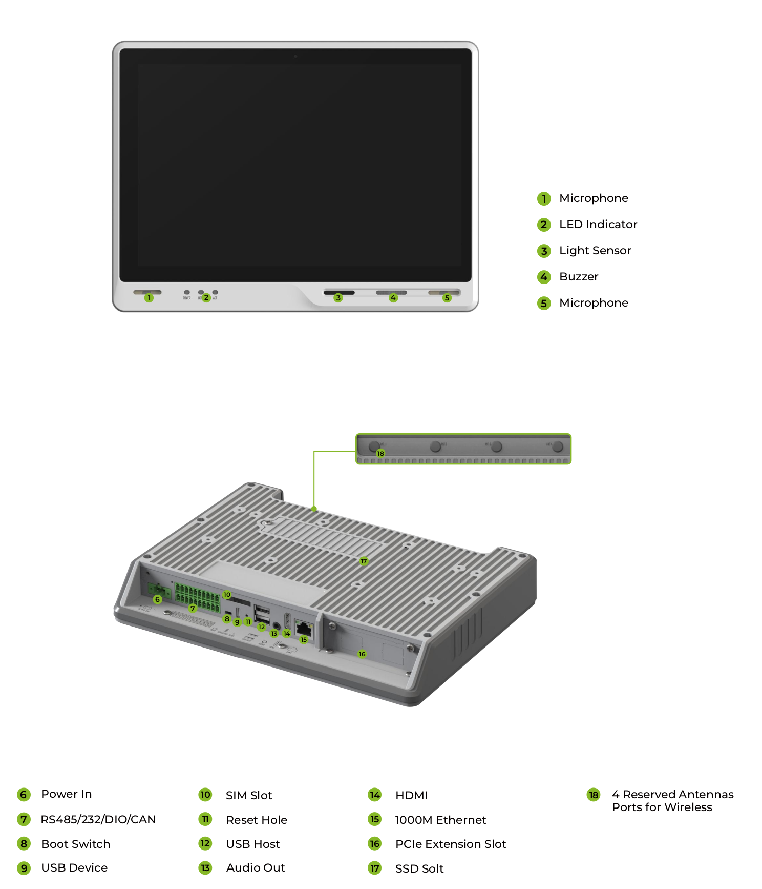
Hardware Overview
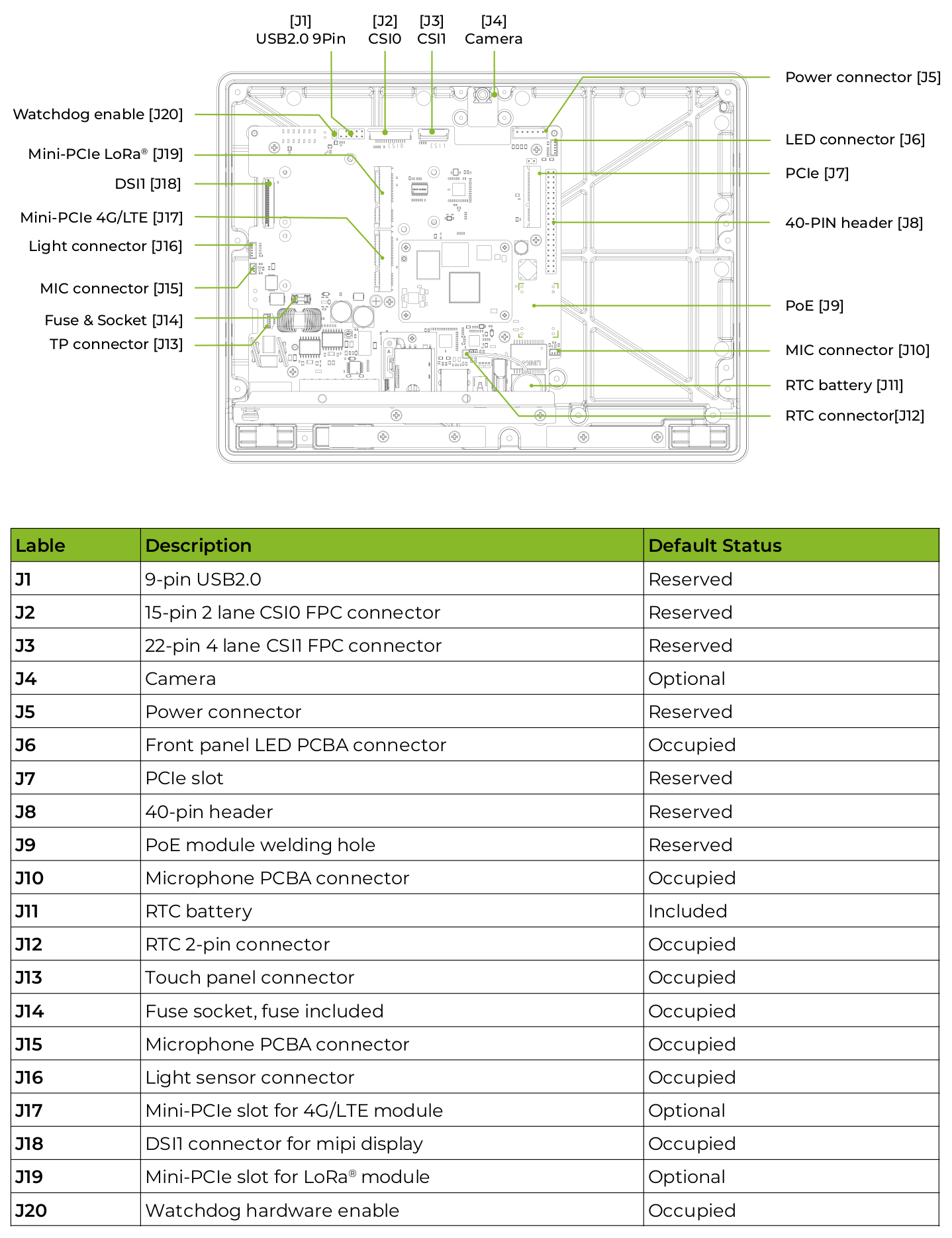
Mainboard Overview
Power Diagram
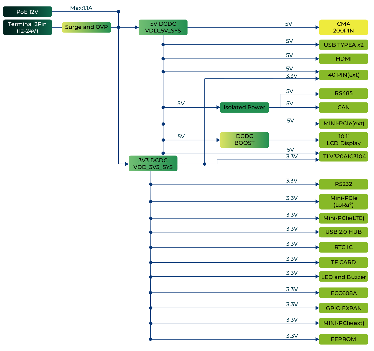
The reTerminal DM supports two power supply options: DC terminal and PoE port. By default, the reTerminal DM is powered through the DC terminal, while the PoE power supply is optional. This provides flexibility in power supply selection and allows for easy integration with various power sources.
Power terminal

The reTerminal DM is supplied with a nominal voltage of 12~24 V. The power supply is connected via the 2-pin power terminal block connector.
POE (optional)
The standard product does not include a PoE module by default, Seeed can provide PoE soldering and assembly services for batch customization orders on request, please contact [email protected],
If the PoE module installed, the LAN1 port of reTerminal DM can support PoE power supply, providing a convenient and efficient way to power the device over Ethernet. This option simplifies the installation process and reduces the amount of cabling required, making it an ideal solution for applications with limited power sources or where power outlets are not readily available.
- PoE input: Range 44~57V; Typical 48V
- PoE output: 12V, 1.1A Max.
Power Consumption
Please refer to the table below for the tested power consumption of reTerminal DM in Seeed Studio's laboratory. Please note that this value is for reference only, as the test methods and environment can result in variations in the results.
| Status | Voltage | Current | Power Consumption | Description |
|---|---|---|---|---|
| Shutdown | 0.6mA | Static power consumption test in shutdown and power-off state. | ||
| Idle | 24V | 0.165A | 3.96W | To test the input current when supplying 24V power to the reTerminal DM device through the Terminal socket while running the default Seeed Studio system, without running any test programs. |
| Full Load | 24V | 0.37A | 8.88W | Configure CPU to run at full load using the "stress -c 4" command, while playing a video and performing CAN & RS485 communication. No external devices connected. |
Power On and Power Off
The reTerminal DM does not come with a power button by default, and the system will automatically start up once power is connected. When shutting down, please select the shutdown option in the operating system and wait for the system to fully shut down before cutting off power. To restart the system, simply reconnect the power.
Please note that after shutting down, please wait for at least 10 seconds before restarting the system to allow for the internal capacitors to fully discharge.
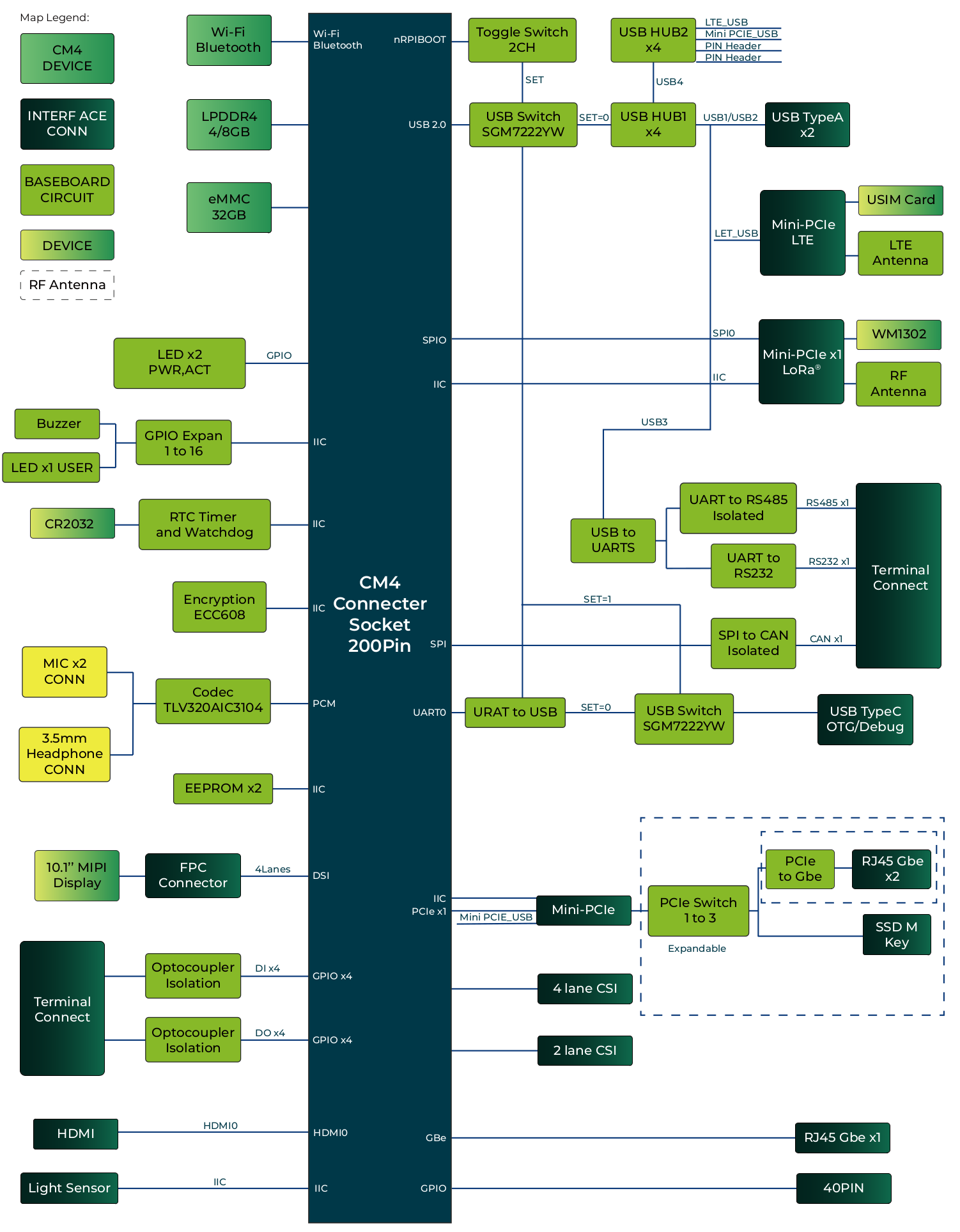
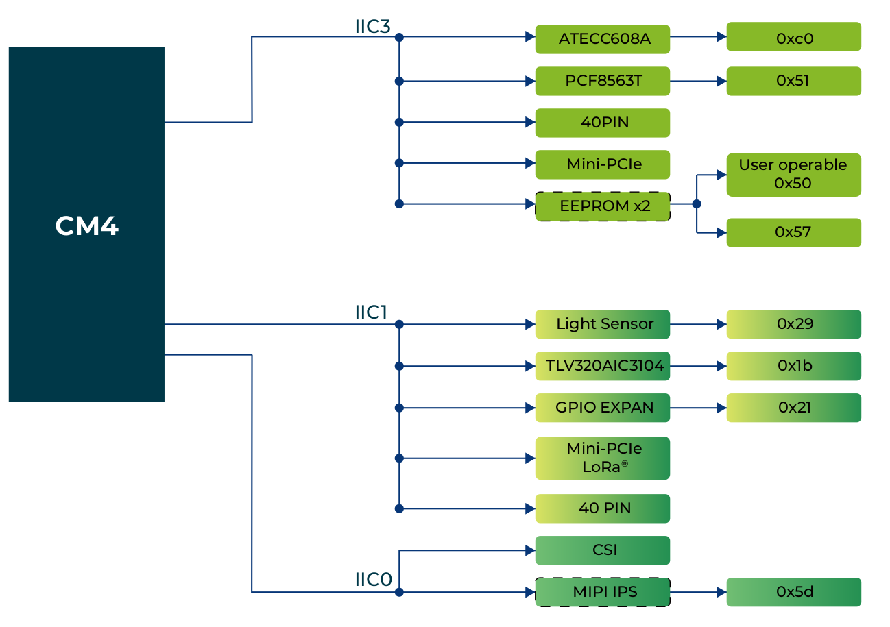
Block Diagram
I2C block
Interface
Microphone
The reTerminal DM is equipped with two MEMS microphones located on the left and right sides below the screen. These microphones can be configured as a dual microphone array, providing superior sound pickup capabilities. The microphones communicate with the audio codec chip through the I2S interface, while the codec chip communicates with CM4 through the PCM interface. The audio codec chip selected for the reTerminal DM is the TI TLV320AIC3104 Low-Power Stereo Audio Codec.
It's important to note that in order to achieve an IP65 rating for the front panel, the microphone openings are covered with a waterproof acoustic membrane. Please avoid using sharp objects to touch the microphone openings.
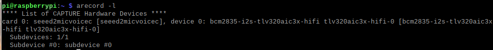
To interface with the Microphone:
Please open the Terminal APP on device and type arecord -l to find the Microphone driver:
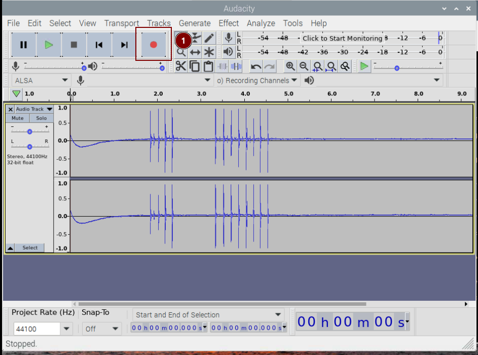
To record the audio you can use the audacity app, please use the sudo apt install audacity to install the audacity app:
Please open the audacity to open the app and click record to records audo from the built-in microphones:
LED Indicator

The reTerminal DM features three LED indicators that serve to signal the machine's operational status. Please refer to the table below for the specific functions and states of each LED:
LED pin assignment
| Label | Signal | Signal Source | Color | Description |
|---|---|---|---|---|
| PWR | LED_nPWR | CM4 | Yellow | Used to indicate the power supply of CM4. When the CM4 is powered on normally, the LED will light up |
| USER | PCA9535 - GPIO | Red | User defined function | |
| ACT | LED_nACT | CM4 | Green | Used to indicate various states of the system. See the table below. |
ACT Status table
| Long flashes | Short flashes | Status |
|---|---|---|
| 0 | 3 | Generic failure to boot |
| 0 | 4 | start*.elf not found |
| 0 | 7 | Kernel image not found |
| 0 | 8 | SDRAM failure |
| 0 | 9 | Insufficient SDRAM |
| 0 | 10 | In HALT state |
| 2 | 1 | Partition not FAT |
| 2 | 2 | Failed to read from partition |
| 2 | 3 | Extended partition not FAT |
| 2 | 4 | File signature/hash mismatch - Pi 4 |
| 4 | 4 | Unsupported board type |
| 4 | 5 | Fatal firmware error |
| 4 | 6 | Power failure type A |
| 4 | 7 | Power failure type B |
If the ACT LED blinks in a regular four blink pattern, it cannot find bootcode (start.elf)
If the ACT LED blinks in an irregular pattern then booting has started.
If the ACT LED doesn't blink, then the EEPROM code might be corrupted, try again without anything connected to make sure.
For more detail please check the Raspberry Pi forum:
STICKY: Is your Pi not booting? (The Boot Problems Sticky) - Raspberry Pi Forums
For more detail please check the Raspberry Pi forum: https://forums.raspberrypi.com//viewtopic.php?f=28&t=58151
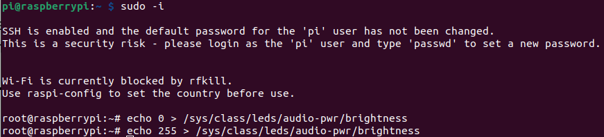
To active the USER Led please use following command:
sudo -i

echo 0 > /sys/class/leds/usr-led/brightness
echo 1 > /sys/class/leds/usr-led/brightness
You should see the USER LED light up with red color.
Light Sensor

The light sensor, located at the bottom right of the screen, is capable of detecting ambient light intensity and automatically adjusting screen brightness to provide an optimal viewing experience while conserving energy. The light sensor communicates with the CM4 through I2C protocol.
The I2C address is 0x29.
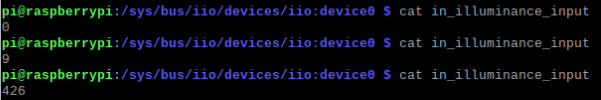
To interface with the light sensor:
- Step 1. Enter the following directory
cd /sys/bus/iio/devices/iio:device0
- Step 2. Type the following to obtain the light intensity value in Lux
cat in_illuminance_input
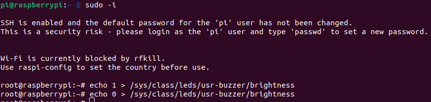
Buzzer

The reTerminal DM features an active buzzer located at the bottom right corner of the screen, which can be used for various purposes such as alarm and event notifications. The buzzer is controlled through the PCA9535 GPIO expansion IC, which provides additional digital I/O channels for the device.
To test and control the buzzer you can simply set the 1 or 0 to the /sys/class/leds/usr-buzzer/brightness file:
Multi-functional Terminals
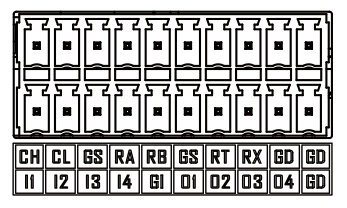
Terminal and signal comparison table
| CANH | CANL | GND_ISO | RS485A | RS485B | GND_ISO | RS232_TX | RS232_RX | GND | GND |
|---|---|---|---|---|---|---|---|---|---|
| DI1 | DI2 | DI3 | DI4 | GND_DI | DO1 | DO2 | DO3 | DO4 | GND_DO |
Terminal pin assignment table
| Pin | Silk-screen | Signal | Description |
|---|---|---|---|
| 1 | CH | CANH | Differential CAN signal high |
| 2 | CL | CANL | Differential CAN signal low |
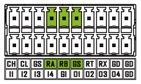
| 3 | GS | GND_ISO | Isolated ground signal |
| 4 | RA | RS485A | Differential RS485 signal A |
| 5 | RB | RS485B | Differential RS485 signal B |
| 6 | GS | GND_ISO | Isolated ground signal |
| 7 | RT | RS232_TX | RS232 signal transmit end |
| 8 | RX | RS232_RX | RS232 signal receive end |
| 9 | GD | GND | Mainboard ground |
| 10 | GD | GND | Mainboard ground |
| 11 | I1 | DI1 | Digital input 1 |
| 12 | I2 | DI2 | Digital input 2 |
| 13 | I3 | DI3 | Digital input 3 |
| 14 | I4 | DI4 | Digital input 4 |
| 15 | GI | GND_DI | Input ground signal, connected with GND via 1MΩ |
| 16 | D1 | DO1 | Digital output 1 |
| 17 | D2 | DO2 | Digital output 2 |
| 18 | D3 | DO3 | Digital output 3 |
| 19 | D4 | DO4 | Digital output 4 |
| 20 | GO | GND_DO | Output ground signal,connected with GND via 0Ω |
DI/DO
The reTerminal DM supports 4 digital input and 4 digital output channels, all of which are optically isolated to effectively protect the mainboard from voltage spikes or other electrical disturbances.
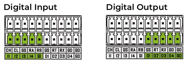
DI/DO pin assignment table
| Pin | CM4 Signal | Typical Voltage Range | Max. Voltage | Rated Current Capacity |
|---|---|---|---|---|
| DI1 | GPIO16 | 5-24V DC | 30V DC | |
| DI2 | GPIO17 | 5-24V DC | 30V DC | |
| DI3 | GPIO22 | 5-24V DC | 30V DC | |
| DI4 | GPIO23 | 5-24V DC | 30V DC | |
| GND_DI | ||||
| DO1 | GPIO24 | 5-24V DC | 30V DC | 500mA |
| DO2 | GPIO25 | 5-24V DC | 30V DC | 500mA |
| DO3 | GPIO26 | 5-24V DC | 30V DC | 500mA |
| DO4 | GPIO6 | 5-24V DC | 30V DC | 500mA |
| GND_DO |
The ground for the input signals is different from the ground for the output signals. The ground for the input signals should be connected to the GND_DI pin, while the ground for the output signals should be connected to the GND_DO pin.
The negative logic used for the digital inputs and outputs of reTerminal DM, the logic level relationship between Terminal IO and CM4 GPIO is shown in the table below.
| Terminal Digital Input | CM4 GPIO Detect Signal |
|---|---|
| Low | High |
| High | Low |
| CM4 GPIO Output | Terminal Digital Output |
|---|---|
| High | Low |
| Low | High |
In this setion we will use the raspi-gpio tool to test with GPIOs, you can use the raspi-gpio help to view the manual:
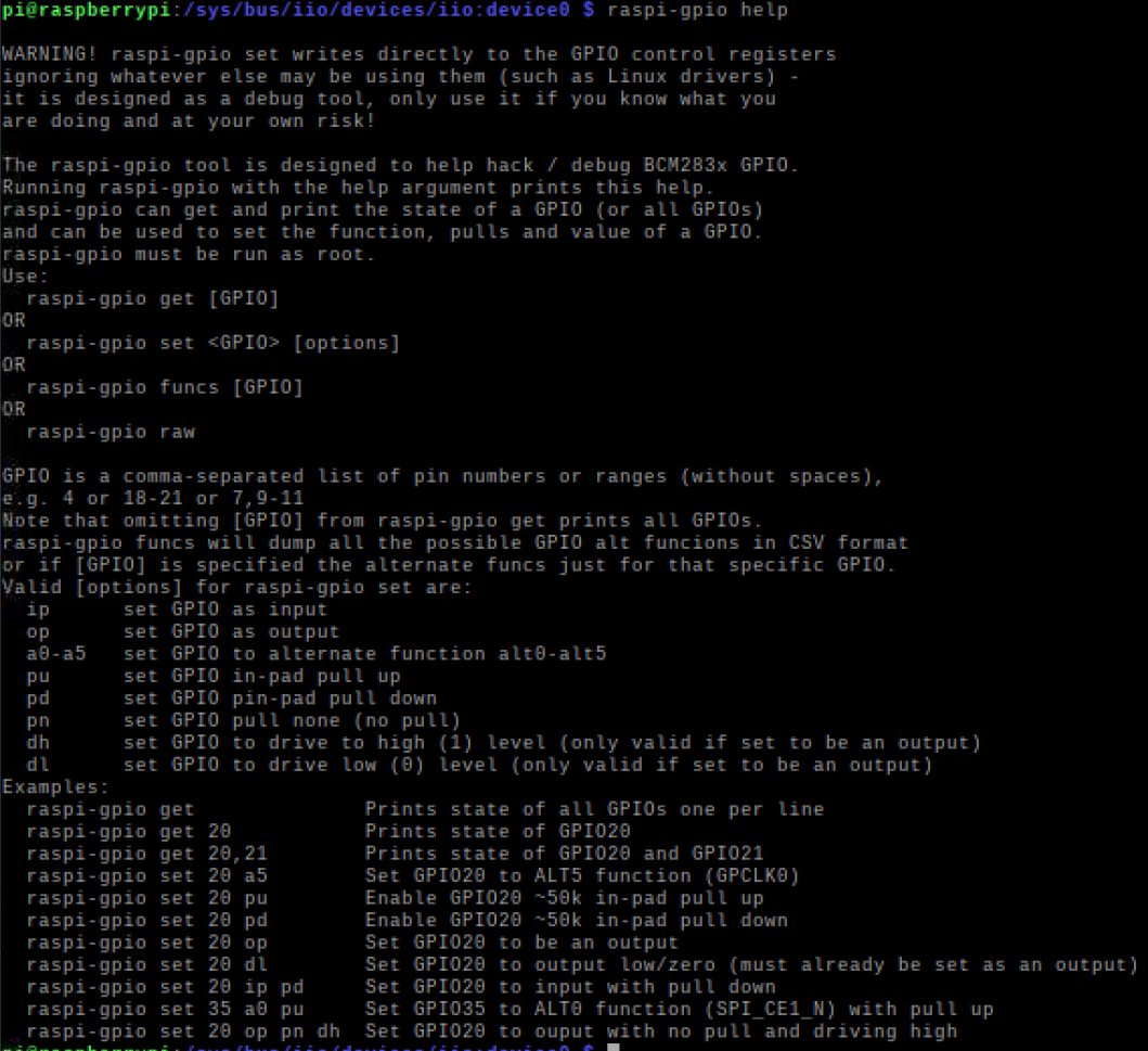
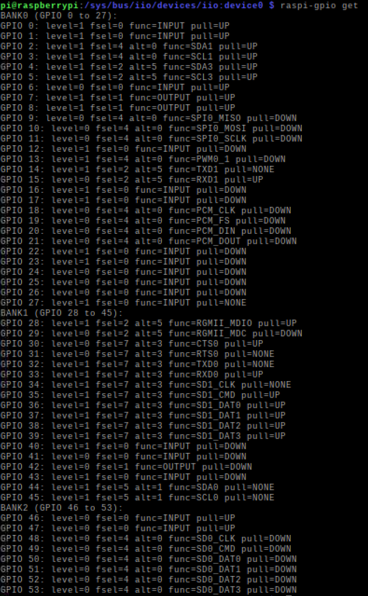
To get the current state of all the GPIOs, Please enter following command in the Terminal:
raspi-gpio get
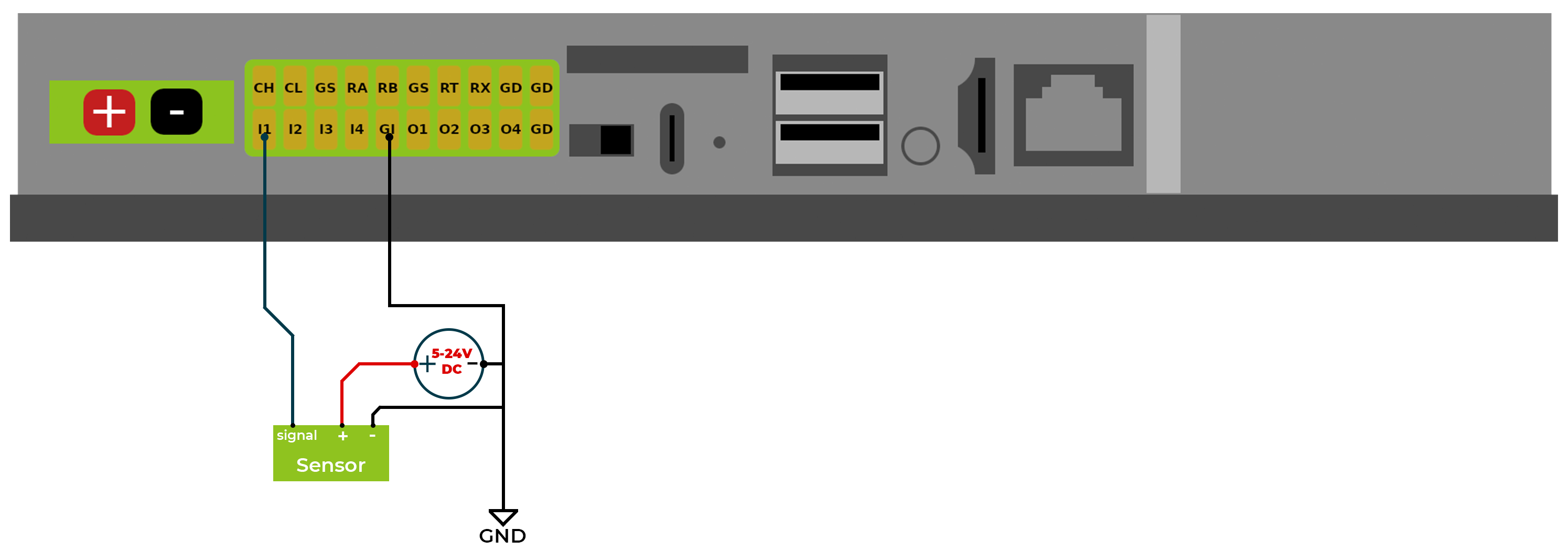
Digital Input
Here is a schematic shown on how to wiring sensors to DI:
To get specific GPIO status, Please enter following command in the Terminal :
raspi-gpio get 16

where the current state of the GPIO16 is set as INPUT and pulling Down the current pin level is 1 which means High which also means the current Terminal Digital Input DI1 is Low according to the above table
Let's put a High signal of the the DI1 by connect the DI1 terminal to the Positive pin of the 5V source, then the Ground from the 5V source to the GND_DI
raspi-gpio get 16

Which the current pin level of the GPIO16 is 0 which means Low which also means the current Terminal Digital Input DI1 is High according to the above table
Digital Output
Here is a schematic shown on how to wiring Load to DO:
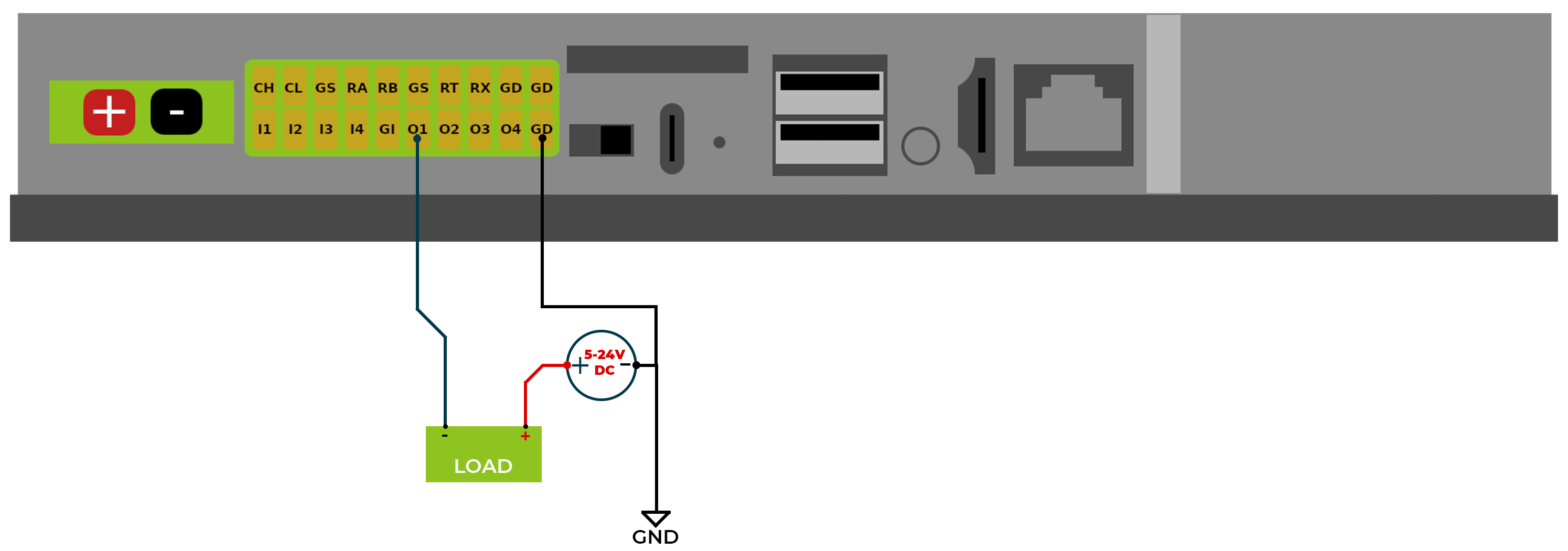
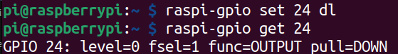
To Control the Digital output state value, first of all we need to set the pin state to Output and pulling Down:
#set current pin state
raspi-gpio set 24 op pd dh

#get the pin state after set
raspi-gpio get 24
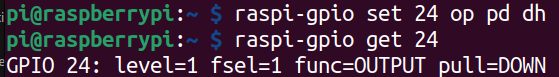
Which the GPIO24 correspond to DO1 is set to the Output and pulling down state, and the GPIO24 level is set to High
Now lets set the GPIO24 to Low which means DO1 Output is driven as High.
#set current pin state
raspi-gpio set 24 dh

#get the pin state after set
raspi-gpio get 24
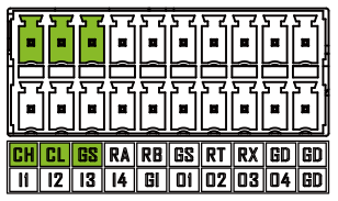
RS485
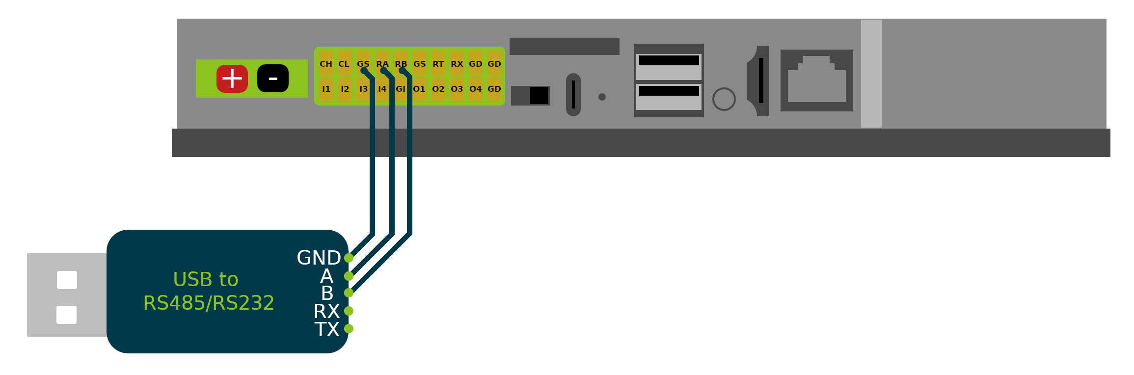
The reTerminal DM is equipped with an RS485 interface through its 20-pin connector, which is isolated for both signal and power to ensure safe and reliable operation in rugged and automation applications. The RS485 A and RS485 B signals are isolated using capacitive isolation, which provides excellent EMI immunity and meets the high-speed communication requirements of the RS485 interface.
A terminal resistor of 120Ω has been installed by default. The RS485 interface uses an isolated power supply, which means that the ground signal for external devices connected to the RS485 interface should be connected to the GND_ISO pin.
To test and interface with the RS485, you should prepare a USB to RS485 adapter, and please make sure the connection is the same as below:
Please note that the RS485 port is /dev/ttyACM1 or /dev/ttyCH340USB1 depends which OS you are running.
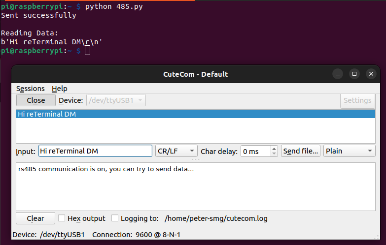
Please use your favorite serial communication tool on your host computer for preform the test below: run the python code on reTerminal DM to test the RS485 serial connection, where this code will set the RS485 serial port as following
Baudrate -> 9600 Bytesize -> 8 bits Parity -> None Stopbits -> 1 Hardware flow control -> disabled
import serial, time
import os

ser = serial.Serial()
if os.path.exists('/dev/ttyACM1'):
    ser.port = "/dev/ttyACM1"
elif os.path.exists('/dev/ttyCH340USB1'):
    ser.port = "/dev/ttyCH340USB1"
else:
    print('Neither /dev/ttyACM1 nor /dev/ttyCH340USB1 is present')

#9600,N,8,1
ser.baudrate = 9600
ser.bytesize = serial.EIGHTBITS    #number of bits per bytes
ser.parity = serial.PARITY_NONE    #set parity check
ser.stopbits = serial.STOPBITS_ONE #number of stop bits

ser.timeout = 0.5                  #non-block read 0.5s
ser.writeTimeout = 0.5             #timeout for write 0.5s
ser.xonxoff = False                #disable software flow control
ser.rtscts = False                 #disable hardware (RTS/CTS) flow control
ser.dsrdtr = False                 #disable hardware (DSR/DTR) flow control

try:
    ser.open()
except Exception as ex:
    print ("open serial port error " + str(ex))
    exit()

if ser.isOpen():
    try:
        ser.flushInput() #flush input buffer
        ser.flushOutput() #flush output buffer
        time.sleep(0.1)
        #write data
        ser.write("rs485 communication is on, you can try to send data...\n".encode())
        print("Sent successfully\n")
        time.sleep(5)  #wait 5s
        #read data
        numofline = 0
        print("Reading Data:")
        while True:
            response = ser.readline()
            print(response)
            numofline = numofline +1
            if (numofline >= 1):
                break
            ser.close()
    except Exception as e1:
        print ("communicating error " + str(e1))
else:
    print ("open serial port error")
RS232
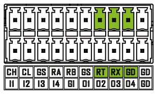
The reTerminal DM's 20-pin connector also includes an RS232 interface, which is not isolated. Because RS232 communication typically uses CMOS voltage levels and has short communication distances, making it less susceptible to electromagnetic interference from the environment.
Please note that the Ground pin needs to connected the GD pin next to the RX pin, make sure it is not the GS pin.
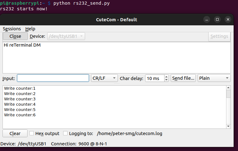
Here is the test python script on sending data from reTerminal DM to host computer:
import time
import serial
import os

if os.path.exists('/dev/ttyACM0'):
    port = "/dev/ttyACM0"
elif os.path.exists('/dev/ttyCH340USB0'):
    port = "/dev/ttyCH340USB0"
else:
    print('Neither /dev/ttyACM0 nor /dev/ttyCH340USB0 is present')

ser = serial.Serial(
port = port,
baudrate = 9600,
parity = serial.PARITY_NONE,
stopbits = serial.STOPBITS_ONE,
bytesize = serial.EIGHTBITS,
timeout = 1
)
counter=0
try:
        print("rs232 starts now!\n")
        ser.write("rs232 starts now!\n".encode())
        while 1:
                ser.write(("Write counter:{}\n".format(counter)).encode())
                time.sleep(1)
                counter += 1
except KeyboardInterrupt:
    exit()
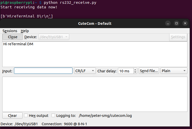
Here is the test python script on receiving data on reTerminal DM send from host computer,
import time
import serial
import os

if os.path.exists('/dev/ttyACM0'):
    port = "/dev/ttyACM0"
elif os.path.exists('/dev/ttyCH340USB0'):
    port = "/dev/ttyCH340USB0"
else:
    print('Neither /dev/ttyACM0 nor /dev/ttyCH340USB0 is present')

ser = serial.Serial(
        port=port,
        baudrate = 9600,
        parity=serial.PARITY_NONE,
        stopbits=serial.STOPBITS_ONE,
        bytesize=serial.EIGHTBITS,
        timeout=1,
        xonxoff = False,                #disable software flow control
        rtscts = False,                 #disable hardware (RTS/CTS) flow control
        dsrdtr = False
)
try:
    print("Start receiving data now!\n")
    while 1:
            x=ser.readlines()
            if x != b'':
                print(x)
except KeyboardInterrupt:
        exit()
CAN
The reTerminal DM features a CAN interface that supports the CAN FD (Controller Area Network Flexible Data-Rate) protocol. The CAN interface is isolated using capacitive isolation, which provides excellent EMI protection and ensures reliable communication in rugged and automation applications. A terminal resistor of 120Ω has been installed by default.
The CAN interface uses an isolated power supply, which means that the ground signal for external devices connected to the CAN interface should be connected to the GND_ISO pin
To test and interface with CAN bus: Please connect the USB to CAN adapter like shown in the image below:
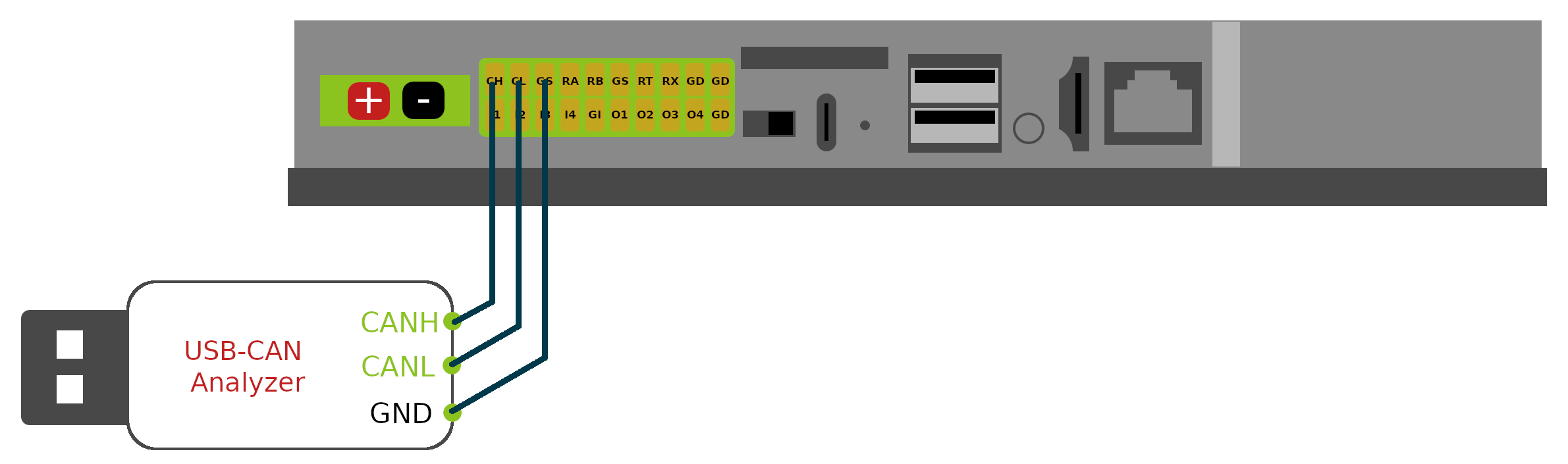
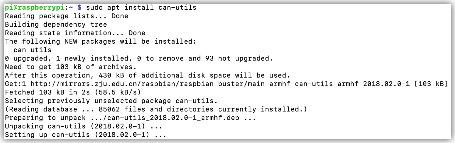
- STEP 1: Install the CAN-utils
sudo apt install can-utils
CAN-utils is a collection of extremely useful debugging tools using the CAN interface. It includes applications such as:
- candump – Dump can packets – display, filter and log to disk.
- canplayer – Replay CAN log files.
- cansend – Send a single frame.
- cangen – Generate random traffic.
- canbusload – display the current CAN bus utilisation
CAN-utils source can be obtained from the GitHub repository.
- STEP 2: Setup CAN interface using the following command:
sudo ip link set can0 up type can bitrate 500000
sudo ifconfig can0 txqueuelen 1000
sudo ip link set can0 up
- STEP 3: Download the testing code to reTerminal DM by using git
git clone https://github.com/limengdu/Seeed_reTerminal_Bridge_CAN_exmaple
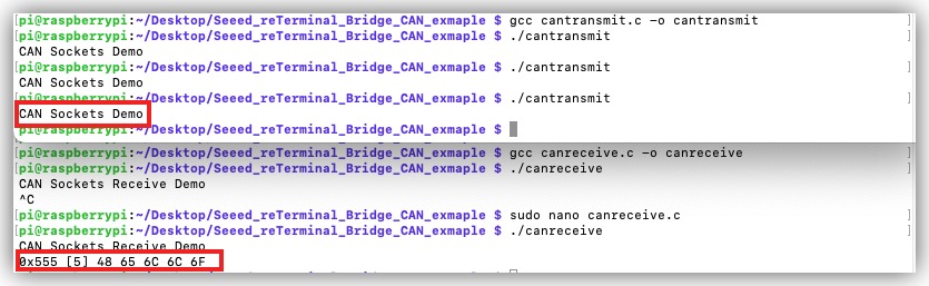
- STEP 4: Compiles and runs the code that sends the data:
cd Seeed_reTerminal_Bridge_CAN_exmaple/
gcc cantransmit.c -o cantransmit
on you Linux host computer or another reTerminal DM, you can compiles and runs the code that receives the data.
gcc canreceive.c -o canreceive
you can see the results, the image below is done by using the two reTerminal DM:
USB
USB Type-A
There are two times of USB 2.0 Type-A ports, which you can connect USB devices such as flash drive, webcam, keyboard and mouse, etc.
USB Type-C

USB Type-C is a USB 2.0 port used for serial debugging or flashing OS image depends on the boot switch position. For flashing OS please refer to Flashing OS Wiki page
SIM Card Slot

The reTerminal DM uses a standard-size SIM card slot commonly found in rugged applications, which requires a standard SIM card with dimensions of 25mm x 15mm.
Please note that the standard version of reTerminal DM does not come with a 4G module. If you require 4G functionality, an additional 4G module must be purchased separately, Therefore this SIM card slot only works if you placed the supported version of 4G module in the 4G PCIe slot.
Reset button

There is a Mini Push Button Switch located in the reset hole of reTerminal DM. By pressing this button with a thin object, the CM4 can be reset. This button is connected to the RUN_PG pin of the CM4. This pin when high signals that the CM4 has started. Driving this pin low resets the module.
Audio Jack

reTerminal DM has a 3.5mm headphone jack, which supports sound output, and can be connected to external headphones, speakers, etc.
The headphone jack only supports sound output and does not support the microphone recording function.
HDMI

The reTerminal DM features a native HDMI interface from CM4, supporting up to 4K @ 60 fps video output. It is ideal for applications that require multiple displays, allowing users to output their content to external large screens.
Ethernet RJ45
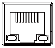
The reTerminal DM comes with a CM4 native Gigabit Ethernet interface that supports three different speeds: 10/100/1000 Mbit/s. An additional PoE module can be purchased to enable power-over-Ethernet (PoE) delivery through this interface, providing power to the reTerminal DM.
Internal Interface
40-Pin GPIO
The classic Raspberry Pi 40-pin GPIO design is retained inside the reTerminal DM, and the pin dentition remains the same as the Raspberry Pi 4B. Users need to open the back cover to use these GPIOs, It should be noted that due to the limited resources of CM4 IO, the 40-pin GPIO and many peripheral interfaces are multiplexed, so you need to pay special attention to the conflict when using GPIOs. For detailed pin assignment information, please refer to the following table.
| Description | Pin multiplexing | Pin multiplexing | Description | |||
|---|---|---|---|---|---|---|
| Pin 1 | 3V3 | 40 PIN GPIO | 5V | |||
| I2C1_SDA | GPIO 2 | 5V | ||||
| I2C1_SCL | GPIO 3 | GND | ||||
| I2C3_SDA | GPIO 4 | GPIO 14 | UART0_TXD | USB Type C | ||
| GND | GPIO 15 | UART0_RXD | ||||
| Block Terminal DI2 | DI2 | GPIO 17 | GPIO 18 | PCM_CLK | 3.5mm audio jack | |
| Interrupt pins for screen touch | TP_INT | GPIO 27 | GND | |||
| Block Terminal DI3 | DI3 | GPIO 22 | GPIO 23 | DI4 | Block Terminal DI4 | |
| 3V3 | GPIO 24 | DO1 | Block Terminal DO1 | |||
| CAN and LoRa® module | SPI0_MOSI | GPIO 10 | GND | |||
| SPI0_MISO | GPIO 9 | GPIO 25 | DO2 | Block Terminal DO2 | ||
| SPI0_SCLK | GPIO 11 | GPIO 8 | SPI0_CE0 | SPI enable pins for CAN | ||
| GND | GPIO 7 | SPI0_CE1 | SPI enable pins for LoRa® | |||
| ID_SD | ID_SC | |||||
| I2C_SCL | GPIO 5 | GND | ||||
| Block Terminal DO4 | DO4 | GPIO 6 | GPIO 12 | CAN_INT | Interrupt pins for CAN | |
| LCD backlight control pins | LCD_PWM | GPIO 13 | GND | |||
| 3.5mm audio jack | PCM_FS | GPIO 19 | GPIO 16 | DI1 | Block Terminal DI1 | |
| Block Terminal DO3 | DO3 | GPIO 26 | GPIO 20 | PCM_DIN | 3.5mm audio jack | |
| GND | GPIO 21 | PCM_DOUT | 3.5mm audio jack |
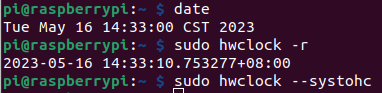
RTC
The reTerminal DM features an RTC circuit that comes pre-installed with a CR2032 battery, enabling it to maintain timekeeping functionality even in the event of power loss.
Use the following command to change the hardware clock with current system clock
sudo hwclock --systohc
Use the following command to change the system clock with current hardware clock
sudo hwclock --hctosys
To veiw the current hardware clock
sudo hwclock -r
Watchdog
The reTerminal DM comes equipped with an independent hardware watchdog circuit that ensures automatic system reboot in case of abnormal system crashes. The watchdog circuit is implemented through RTC and allows for flexible feeding times from 1 to 255 seconds.
To configure the watchdog timeout time in watchdog.conf, please follow these steps:
STEP 1: Open the watchdog.conf file for editing, usually located at /etc/watchdog.conf.
sudo nano /etc/watchdog.conf
STEP 2: Look for the "watchdog-device" and "watchdog-timeout" configuration options under the /etc/watchdog.conf, please set as following.
you might experience instant restart when watchdog-timeout option is set under 60, to utilise the Hardware watchdog you need to config the watchdog-device as /dev/watchdog1, where the default config without 1 is utilising the Broadcom watchdog device.
# Uncomment this to use the watchdog device driver access "file".

watchdog-device  = /dev/watchdog1

# Uncomment and edit this line for hardware timeout values that differ
# from the default of one minute.

watchdog-timeout = 60
For example, if you want to set the watchdog timeout time to 60 seconds, you can set the value of watchdog-timeout to 60, which means that if the watchdog does not receive a reset signal within 60 seconds, it will trigger an automatic reboot operation, assuming the system has crashed.
you can test if the watchdog is active with following command, where these command will put system in halt please be carefull on proferm the follow commands:
sudo su
echo 1 > /proc/sys/kernel/sysrq
echo "c" > /proc/sysrq-trigger
Now your reTerminal DM should have rebooted after the time you have set to the watchdog-timeout
Backlight
There are 6 steps of brightness you can set to the backlight, from 0 is switch off to 5 is the maximum brightness. You could interface on controlling the brightness by using following commands.
sudo -i

echo 0 > /sys/class/backlight/lcd_backlight/brightness
echo 1 > /sys/class/backlight/lcd_backlight/brightness
echo 5 > /sys/class/backlight/lcd_backlight/brightness
Internal Add-on
Camera
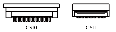
The CSI camera interface is reserved on the reTerminal DM mainboard, which can be customized to support camera functions. Please note that due to the limited space on the front panel, only small-sized cameras can be used. The currently rigorously tested solution uses the Raspberry Pi camera V2.0 driver board + Seeed customized camera IMX219-77.
| Connector | Connector Type | Pin Pitch | Lane | FPC Orientation |
|---|---|---|---|---|
| CSI0 | 15-pin FPC | 1mm | 2 | Gold fingers facing downwards |
| CSI1 | 22-pin FPC | 0.5mm | 4 | Gold fingers facing upwards |
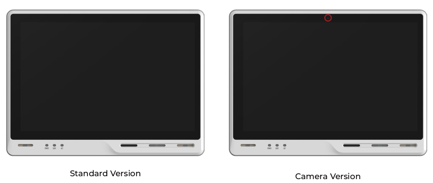
Please note that the standard version of the reTerminal DM does not come with a camera opening on the front panel, therefore, the camera functionality is not available for the standard product. If you have a customized camera requirement, please contact [email protected]
4G Module

Materials Required
- reTerminal DM x 1
- EC25-EUX 4G Module x1
- SIM Card x1
Step 1. Please refer to the EC25 4G Module Hardware assembly guide to install EC25 4G Module into the 4G/LTE PCIe slot which you should see the 4G/LTE slikscreen, and please also put in the 4G enabled sim-card in the sim card slot, before you power up the system.
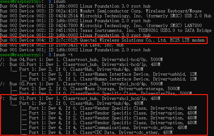
Step 2. Check if EC25-EUX gets detectd by using lsusb
lsusb
lsusb -t
Step 3. Install the serial communication tool minicom.
sudo apt install minicom
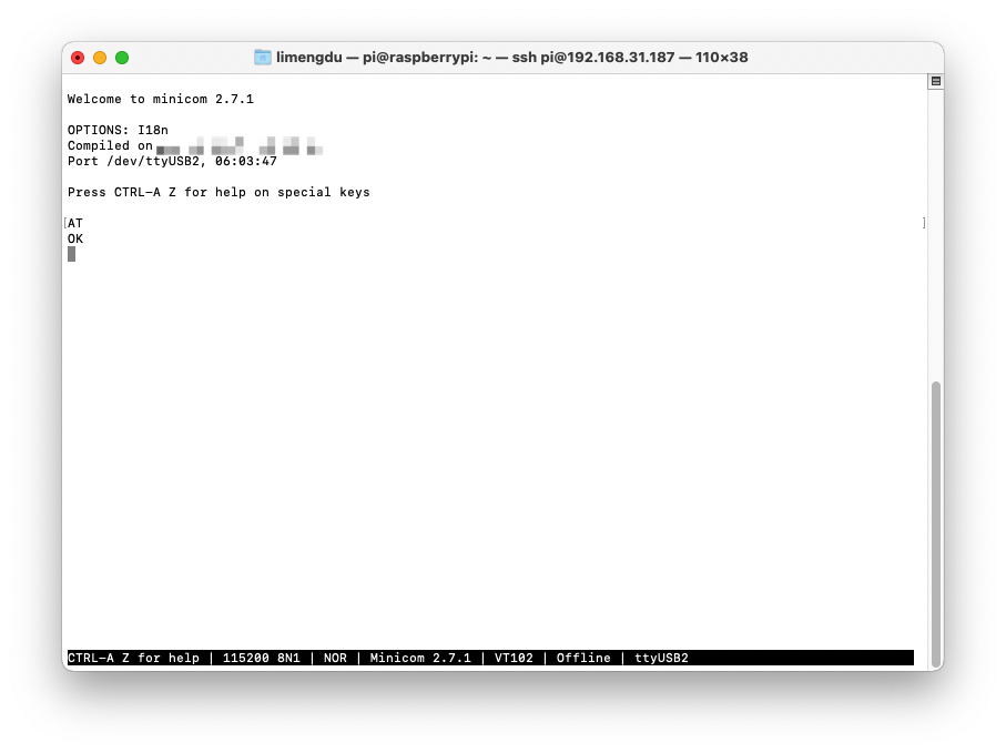
Step 4. Connect EC25-EUX 4G module through minicom.
sudo minicom -D /dev/ttyUSB2 -b 1152008n1
once the serial connection opened, Type in AT and press 'Enter', and you should see OK.
Step 5. Enable 4G module to connect to 4G network
AT the same minicom serial window please type:
AT+QCFG="usbnet"
It will return something like +QCFG: "usbnet",0, but we need that to be set to 1 (ECM mode), so enter the following command:
AT+QCFG="usbnet",1
Then enter the following command to force the modem to reboot:
AT+CFUN=1,1
Then you could reboot or wait for a while for the moudel to get internet from your sim card carrier.
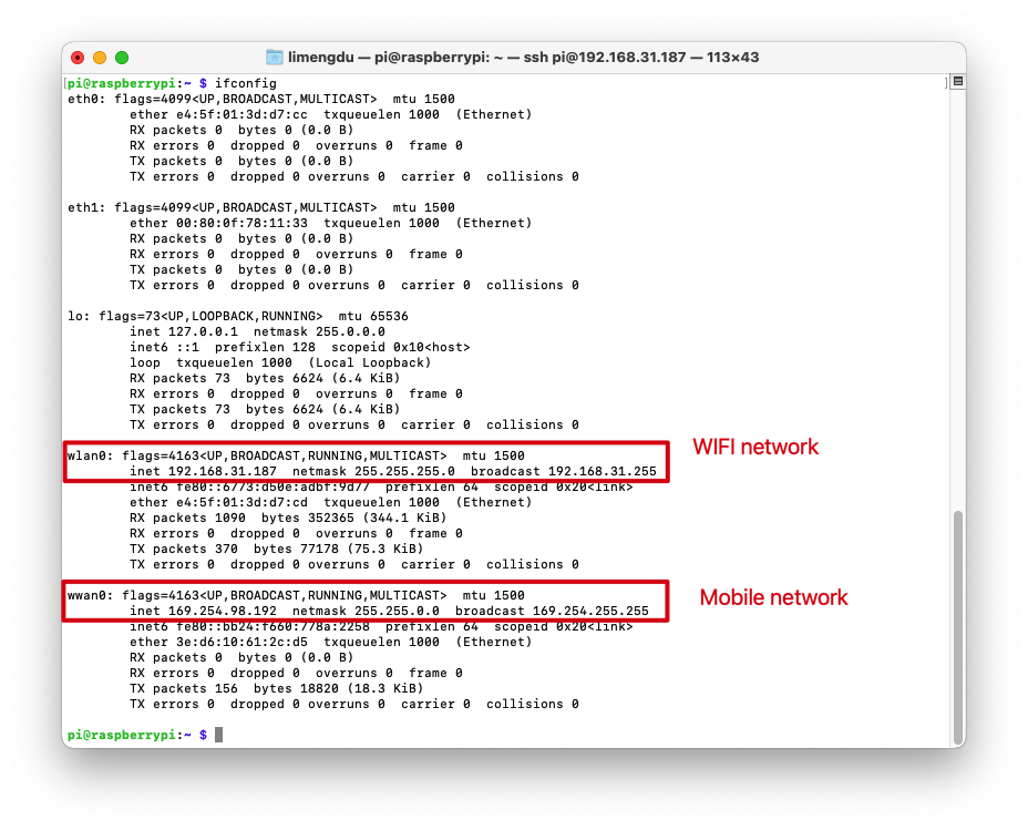
You can also use the command ifconfig to query the networking status of reTerminal DM.
LoraWAN® Module
reTerminal DM support for both USB and SPI version of the WM1302 LoraWAN® Module, however the USB verison will need to uiltising the Mini PCIe designed for 4G Moudle which means if you want to use the both 4G Module and LoraWAN® Module Please choose SPI version of the WM1302 LoraWAN® Module.
- WM1302 SPI Module
- WM1302 USB Module

Step 1. Please refer to the LoraWAN® Module Hardware assembly guide to install WM1302 SPI LoraWAN® Module into the LoraWAN® Mini PCIe slot which you should see the Lora slikscreen.
Install necessary packages build-essential(build essential package is a Debian package that contains the tools needed to create a DEB package from source code.) by installing module.
sudo apt update
sudo apt install git
sudo apt-get install build-essential
Step 2. type sudo raspi-config in command line to open Raspberry Pi Software Configuration Tool:
- Select Interface Options
- Select SPI, then select Yes to enable it
- Select I2C, then select Yes to enable it
- Select Serial Port, then select No for "Would you like a login shell..." and select Yes for "Would you like the serial port hardware..."
After this, please reboot Raspberry Pi to make sure these settings work.
Step 3. Download the WM1302 code to reTerminal and compile it.
cd ~/
git clone https://github.com/Lora-net/sx1302_hal
cd sx1302_hal
sudo make
Step 4. Copy and modify the reset_lgw.sh script
cp ~/sx1302_hal/tools/reset_lgw.sh ~/sx1302_hal/packet_forwarder/
cd ~/sx1302_hal/packet_forwarder
vim reset_lgw.sh
Modify the reset_lgw.sh script with text editor as following:
#!/bin/bash

# Dependency Check
if ! command -v i2cset &> /dev/null; then
    echo "Error: i2c-tools not found. Please install using: sudo apt-get install i2c-tools"
    exit 1
fi

# Configuration
I2C_BUS=1               # CM4_IIC1
DEVICE_ADDR=0x21        # PCA9535 Address from schematic
REG_OUTPUT_PORT0=0x02   # Register 2: Output Port 0
REG_CONFIG_PORT0=0x06   # Register 6: Configuration Port 0
PIN_MASK=0x20           # Bit 5 (0010 0000) for P05

# Read a register
read_reg() {
    local val=$(i2cget -y $I2C_BUS $DEVICE_ADDR $1)
    echo $val
}

# Write to a register
write_reg() {
    i2cset -y $I2C_BUS $DEVICE_ADDR $1 $2
}

echo "Starting SX1302 Reset Sequence on I2C Bus $I2C_BUS, Address $DEVICE_ADDR..."

# Ensure the Output Register bit for P05 is LOW
CURRENT_OUT=$(read_reg $REG_OUTPUT_PORT0)

NEW_OUT=$(printf "0x%02x" $((CURRENT_OUT & ~PIN_MASK)))

write_reg $REG_OUTPUT_PORT0 $NEW_OUT

echo "Set Output Register P05 to LOW. (Reg $REG_OUTPUT_PORT0: $CURRENT_OUT -> $NEW_OUT)"

# Configure P05 as OUTPUT
# Configuration Register: 1 = Input, 0 = Output
CURRENT_CFG=$(read_reg $REG_CONFIG_PORT0)

NEW_CFG=$(printf "0x%02x" $((CURRENT_CFG & ~PIN_MASK)))

write_reg $REG_CONFIG_PORT0 $NEW_CFG

echo "Configured P05 as OUTPUT. (Reg $REG_CONFIG_PORT0: $CURRENT_CFG -> $NEW_CFG)"

# Assert Reset (Drive P05 HIGH)
CURRENT_OUT=$(read_reg $REG_OUTPUT_PORT0)

RESET_HIGH=$(printf "0x%02x" $((CURRENT_OUT | PIN_MASK)))

write_reg $REG_OUTPUT_PORT0 $RESET_HIGH

echo "Asserting Reset (P05 HIGH)..."

# Hold Reset for 200ms
sleep 0.2

# Release Reset (Drive P05 LOW)
write_reg $REG_OUTPUT_PORT0 $NEW_OUT

echo "Released Reset (P05 LOW)."

echo "SX1302 Reset Complete."

echo "------------------------------------"
Step 5. replace the default SPI port of the LoraWAN® Module in the global_conf.json.sx1250.US915 config file:
sed -i 's/spidev0.0/spidev0.1/g' global_conf.json.sx1250.US915
Step 6. Start LoraWAN® Module
Choose your prefered LoRaWAN Network Server server_address and the gateway EUI gateway_ID in the corresponding global_conf.json.sx1250.xxxxx based on the module you are using, and modify the up/down port to 1700. Then run the following code to start the concentrator:
cd ~/sx1302_hal/packet_forwarder
# Please select one of the following comands based on your module
# for WM1302 LoRaWAN Gateway Module (SPI) - EU868
./lora_pkt_fwd -c global_conf.json.sx1250.EU868

# for WM1302 LoRaWAN Gateway Module (SPI) - US915
./lora_pkt_fwd -c global_conf.json.sx1250.US915

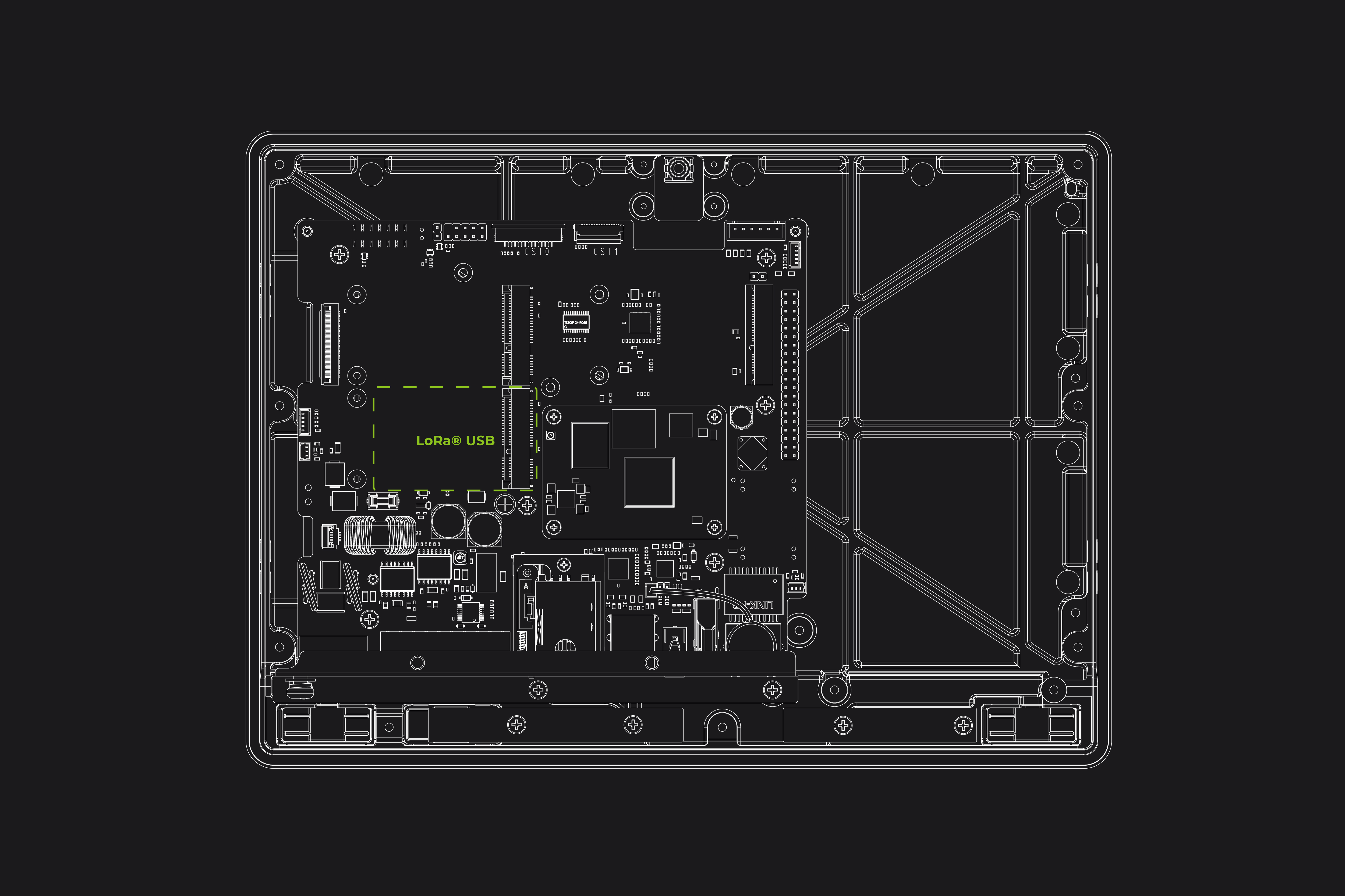
Step 1. Please refer to the LoraWAN® Module Hardware assembly guide to install WM1302 USB LoraWAN® Module into the 4G Mini PCIe slot which you should see the 4G slikscreen.
Step 2. type sudo raspi-config in command line to open Raspberry Pi Software Configuration Tool:
- Select Interface Options
- Select I2C, then select Yes to enable it
- Select Serial Port, then select No for "Would you like a login shell..." and select Yes for "Would you like the serial port hardware..."
After this, please reboot Raspberry Pi to make sure these settings work.
Step 3. Download the WM1302 code to reTerminal and compile it.
cd ~/
git clone https://github.com/Lora-net/sx1302_hal
cd sx1302_hal
sudo make
Step 4. Copy the reset_lgw.sh script
cp ~/sx1302_hal/tools/reset_lgw.sh ~/sx1302_hal/packet_forwarder/
Step 5. replace the USB port of the LoraWAN® Module in the global_conf.json.sx1250.US915.USB config file:
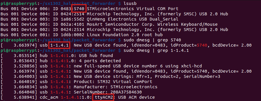
Step 5-1. First to get the specific USB port please follow the steps below:
lsusb
In my case our WM1302 is using the STMicroelectronics Virtual COM Port so we can get the product id 5740
Step 5-2.
Then get the usb device with the Product ID number 5740, In this case we get the USB port number 1-1.4.1:
sudo dmesg | grep 5740
# Load ACM module
sudo modprobe cdc_acm
Then we could get the device port as follow:
sudo dmesg | grep 1-1.4.1
so in my case the USB device is ttyACM2
So lets modify the USB device in the global_conf.json.sx1250.US915.USB config with the sed command sed -i 's/search_string/replacement_string/g' filename, so please follow the pattern as sed -i 's/ttyACM0/the_result_from_above' global_conf.json.sx1250.frequency_of_your_module.USB, to be note that please replace the_result_from_above and frequency_of_your_module for your own application:
for example in my case:
sed -i 's/ttyACM0/ttyACM2/g' global_conf.json.sx1250.US915.USB
Please refer to the steps shown in the image below:
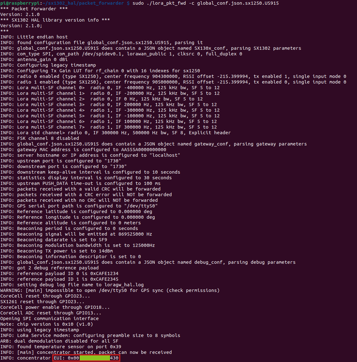
Step 6. Start LoraWAN® Module
Choose your prefered LoRaWAN Network Server server_address and the gateway EUI gateway_ID in the corresponding global_conf.json.sx1250.xxxxx based on the module you are using, and modify the up/down port to 1700. Then run the following code to start the concentrator:
cd ~/sx1302_hal/packet_forwarder

# Please select one of the following comands based on your module

# for WM1302 LoRaWAN Gateway Module (USB) - EU868
./lora_pkt_fwd -c global_conf.json.sx1250.EU868.USB

# for WM1302 LoRaWAN Gateway Module (USB) - US915
./lora_pkt_fwd -c global_conf.json.sx1250.US915.USB

PCIe Expansion Card
The reTerminal DM features a PCIe interface that is derived from the CM4, which supports PCIe 2.0 and theoretically provides a maximum transmission speed of 5Gbps. This allows for the expansion of various high-speed interfaces such as Gigabit Ethernet and NVMe SSD. We have developed multiple expansion cards based on PCIe, USB, and I2C interfaces to meet different scenario requirements. This also facilitates customization needs.
Please note that the standard product does not include a PCIe expansion card by default. Seeed can provide assembly services for batch customization orders.
POE
The reTerminal DM can support the IEEE 802.3af PD(Powered Devices) standard by adding a PoE power supply module.
The reTerminal DM supports PoE power supply, but the standard product does not include a PoE module by default. Seeed can provide PoE soldering and assembly services for batch customization orders. However, if a customer is testing a sample, they will need to solder and assemble the PoE module themselves.
SSD
The reTerminal DM supports 2280 NVMe SSD through the use of a PCIe expansion card. It is important to note that the CM4's PCIe is gen2.0 with a maximum theoretical speed of 5Gbps. If you are using a Gen3.0 or higher SSD, it may not be able to achieve the SSD's maximum speed. After testing, the reTerminal DM with installed SSD can achieve a maximum write speed of 210MB/s and a maximum read speed of 360MB/s. If you are unsure which SSDs are compatible, you can purchase the 112990247, 512GB NVMe M.2 PCle Gen3x4 2280 SSD from Seeed's official website.
The standard version of the reTerminal DM does not support SSD and requires the purchase of a PCIe expansion card to enable this feature.
Additional Resources
- reTerminal DM Datasheet
- reTerminal DM User Manual
- reTerminal DM Schematic Design & PCB Design & Gerber Files
- reTerminal DM Structural Design File.stp
Tech Support & Product Discussion
Thank you for choosing our products! We are here to provide you with different support to ensure that your experience with our products is as smooth as possible. We offer several communication channels to cater to different preferences and needs.