As a sensor & Use Grove
SenseCAP Watcher will be live on Kickstarter on September 12, proudly featuring the official 'Project We Love' badge! Subscribe now to stay informed~
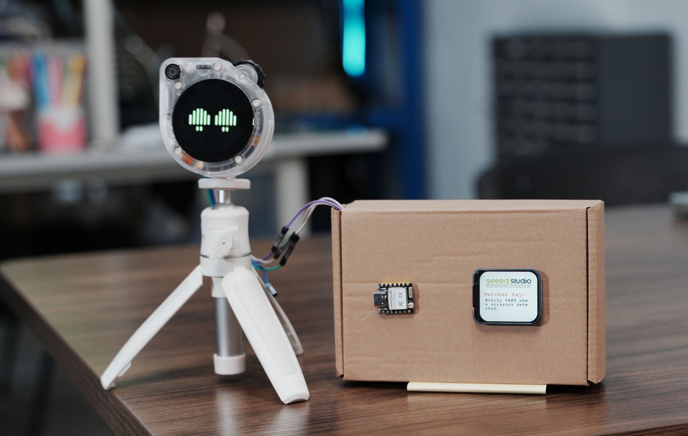
In this wiki, we will explore the exciting possibilities that arise when Watcher, acting as a sensor, leverages its UART (Universal Asynchronous Receiver/Transmitter) functionality. By enabling UART communication, Watcher can transmit valuable data such as captured images and recognition results through its UART interface, located on the back of the device. This opens up a world of opportunities for integrating Watcher with various hardware platforms and creating innovative applications.
Throughout this wiki, we will dive into the details of reading and interpreting the data output from Watcher's UART interface. Additionally, we will provide comprehensive tutorials on how to parse and utilize this data using popular development boards and platforms, including XIAO, Arduino, Raspberry Pi, and Jetson.
Watcher UART wiring
When you are ready to use the UART for message alarms, please connect the Watcher to your MCU as follows.
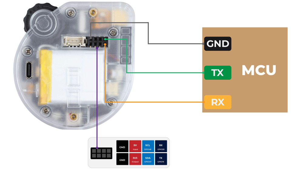
Note that if your Watcher and MCU are powered separately, then you do not need to connect the 3.3V or 5V pins of the Watcher and MCU.
If you are planning to use the Watcher to power the MCU, then you can use 3.3V to power the MCU on top of the wiring in the picture. (Do not use the 5V pins, they are for input only)
If you are planning to use the MCU to power the Watcher, then you can need to use the 5V input. (3.3V may not be enough for the Watcher to work properly)
Enabling UART Functionality in Watcher
To unlock the full potential of Watcher's UART capabilities, we first need to enable the UART functionality within the device. This is particularly useful in scenarios where Watcher is employed as an alarm system. When an alarm is triggered, Watcher can activate its UART communication, allowing it to transmit critical information such as captured images and recognition results to external devices for further processing and analysis.
To enable the UART alarm function, you have two options:
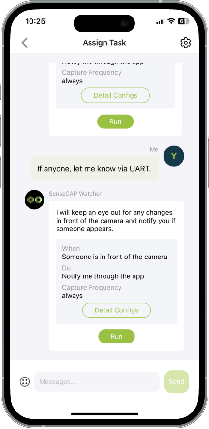
- Explicitly request Watcher to notify you via UART when assigning tasks using the SenseCraft APP.
Manually enable the UART alarm function in the task's detailed settings:
- Access the Detail Config of the task you want to configure.
- Locate the Action section.
- Check the box to enable the Serial Port / UART Output.
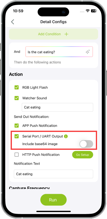
Please choose whether you need to enable the output of images according to your actual application scenario. If Include base64 image is enabled, then your MCU needs at least 70k memory to cache the image.
Once you have enabled the UART alarm function using either of the above methods, Watcher will output the necessary alarm information via UART whenever it detects the specified alarm content. Ensure that Watcher is connected to the appropriate receiving device, such as a microcontroller or a computer with a serial terminal, to capture and process the alarm information transmitted through UART.
Reading UART Output from Watcher
Once UART functionality is enabled, Watcher will begin transmitting data through its UART interface. In this section, we will provide a detailed guide on how to read and interpret the data received from Watcher's UART output. We will cover the necessary hardware connections, communication protocols, and data formats to ensure a smooth and successful data retrieval process.
By default, Watcher uses the following UART configuration: baud rate of 115200, 8 data bits, no parity, 1 stop bit, and no hardware flow control. When connecting to Watcher's UART interface, ensure that your receiving device is configured with the same settings to ensure proper communication.
When Watcher sends alarm information via UART, it follows a specific protocol and format based on the tf_module_uart_alarm_t structure defined in the tf_module_uart_alarm.h header file. The UART protocol and format for Watcher's UART alarm module are as follows:
Output Format
The format of the UART output is controlled by the output_format field.
- When
output_formatis set to 0, the output is in binary format. - When
output_formatis set to 1, the output is in JSON format.
output_format is set to 1 by default to output in JSON.
Binary Output Format
When output_format is set to 0, the structure of the UART output packet is as follows:
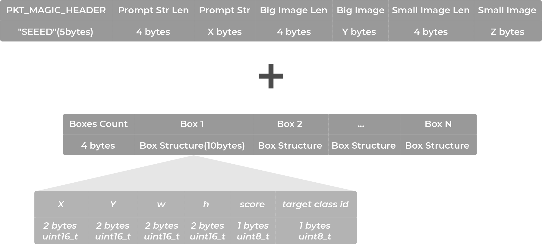
PKT_MAGIC_HEADER: The magic header of the packet, fixed as "SEEED" (5 bytes).Prompt Str Len: The length of the prompt string, 4-byte unsigned integer in little-endian.Prompt Str: The prompt string, used to briefly explain the task that Watcher is performing. If thetextparameter is set, its value is used.Big Image Len: The length of the big image, 4-byte unsigned integer in little-endian. Only included wheninclude_big_imageistrue.Big Image: 640*480 JPG image, base64 encoded, without boxes of detected objects. Only included wheninclude_big_imageistrue.Small Image Len: The length of the small image, 4-byte unsigned integer in little-endian. Only included wheninclude_small_imageistrue.Small Image: 240*240 JPG image, base64 encoded, with boxes drawn for detected objects. Only included wheninclude_small_imageistrue.Boxes Count: The number of detected object boxes, 4-byte unsigned integer in little-endian. Only included wheninclude_boxesistrue.Box Structure: The structure of a detected object box, each box occupies 10 bytes, including coordinates, score, and target class ID. Only included wheninclude_boxesistrue.
The recognised boxes (boxes) message will not be received at this time, as the corresponding feature of Watcher is still under development and has not yet been reported in the latest v1.1 release.
JSON Output Format
When output_format is set to 1, the structure of the UART output packet is as follows:
{
      "prompt": "monitor a cat",
      "big_image": "base64 encoded JPG image, if include_big_image is enabled, otherwise this field is omitted",
      "small_image": "base64 encoded JPG image, if include_small_image is enabled, otherwise this field is omitted",
      "boxes": [
         {
            "x": 100,
            "y": 100,
            "w": 50,
            "h": 60,
            "score": 0.8,
            "target_cls_id": 1
         }
      ]
}
The JSON packet is separated by \r\n.
The recognised boxes (boxes) message will not be received at this time, as the corresponding feature of Watcher is still under development and has not yet been reported in the latest v1.1 release.
Configuration Options
output_format: Controls the format of the UART output, default is 1 (JSON format).text: Used to fill thepromptfield of the output packet.include_big_image: Boolean (true | false), controls whether the big image is included in the output, default istrue.include_small_image: Boolean (true | false), controls whether the small image is included in the output, default istrue.include_boxes: Boolean (true | false), controls whether the boxes are included in the output, default istrue.
Note: If any configuration field is omitted, the default value will be implied.
The recognised boxes (boxes) message will not be received at this time, as the corresponding feature of Watcher is still under development and has not yet been reported in the latest v1.1 release.
XIAO ESP32 Series & Watcher
Learn how to connect Watcher to the XIAO ESP32 Series board and parse the UART data using the Arduino. This section will guide you on how to connect Watcher to the XIAO ESP32 Series board and parse the UART data using Arduino.
Wiring
This tutorial supports the series XIAO:
| XIAO ESP32C3 | XIAO ESP32S3 | XIAO ESP32C6 |
|---|---|---|
 |  |  |
This does not mean that other XIAO series are not supported. Mainly because the message data reported by Watcher takes up about 100k (at least 70k) of memory, we would recommend you to use the ESP32 series of XIAO for the UART part of the Watcher development. If you don't need to parse image data, then the other XIAO's memory is perfectly adequate.
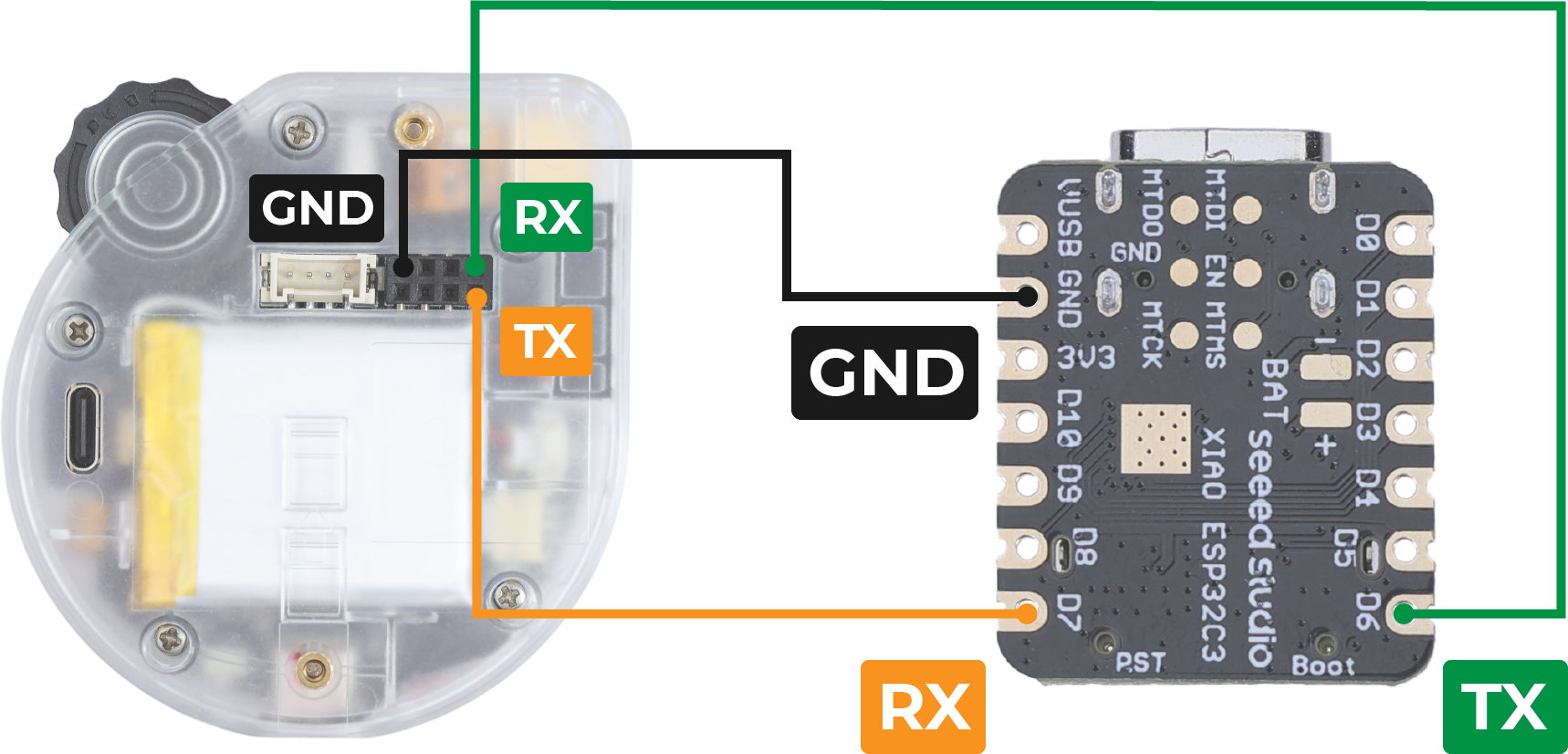
Connect the TX pin of the Watcher to the RX pin of the XIAO's UART interface.
Connect the RX pin of the Watcher to the TX pin of the XIAO's UART interface.
Connect the GND pin of the Watcher to a GND pin on the XIAO.
Code Explanation
You can use any XIAO ESP32 series development board, or any other ESP32 series board to use the following program to read the UART data stream of the Watcher.
Currently, only JSON data streams can be output, so only programs that parse JSON data streams are provided.
Other XIAOs are not always supported, mainly because parsing a JSON stream requires at least 70k of memory.
#include <ArduinoJson.h>

long int count = 0;  // Number of alarms

void setup() {
  Serial.begin(115200);
  Serial1.begin(115200, SERIAL_8N1, D7, D6);  // RX, TX
  while(!Serial);
  delay(100);

  Serial.println("Device Ready. Waiting for Watcher's JSON data...");
}

void loop() {
  if (Serial1.available()) {
    // Set up enough space to store the parsed JSON objects
    const size_t capacity = 1024 * 100 + 512; // At least 70k, insurance 100k
    DynamicJsonDocument doc(capacity);

    // Streaming parsing from Serial1
    DeserializationError error = deserializeJson(doc, Serial1);

    if (error) {
      Serial.print("deserializeJson() failed: ");
      Serial.println(error.c_str());
      return;
    }

    // Print the parsed key-value pairs
    if (doc.containsKey("prompt")) {
      Serial.print("prompt: ");
      Serial.println(doc["prompt"].as<String>());
    }

    if (doc.containsKey("big_image")) {
      Serial.print("big_image: ");
      String big_imageData = doc["big_image"].as<String>();
      // Print only the first 100 characters of the image data for example
      Serial.println(big_imageData.substring(0, 100) + "...");
    }

    if (doc.containsKey("small_image")) {
      Serial.print("small_image: ");
      String small_imageData = doc["small_image"].as<String>();
      // Print only the first 100 characters of the image data for example
      Serial.println(small_imageData.substring(0, 100) + "...");
    }

    // Watcher has not yet been developed and will not output this message at this time
//    if (doc.containsKey("boxes")) {
//      JsonArray boxes = doc["boxes"].as<JsonArray>();
//      for (JsonObject box : boxes) {
//        Serial.print("Box - ");
//        Serial.print("x: ");
//        Serial.print(box["x"].as<int>());
//        Serial.print(", y: ");
//        Serial.print(box["y"].as<int>());
//        Serial.print(", widths: ");
//        Serial.print(box["w"].as<int>());
//        Serial.print(", height: ");
//        Serial.print(box["h"].as<int>());
//        Serial.print(", score: ");
//        Serial.print(box["score"].as<float>());
//        Serial.print(", target_cls_id: ");
//        Serial.println(box["target_cls_id"].as<int>());
//      }
//    }

    count++;
    if(count > 2147483646){  // Spillage prevention
      count = 0;
    }
    Serial.print("The ");
    Serial.print(count);
    Serial.println(" alarm message reception is complete. Wait for the next message...");
    Serial.println("------------------------------------------------------------------");
  }
}
The provided code demonstrates how to receive and parse JSON data from Watcher using the Arduino IDE and the ArduinoJson library. Here's a brief explanation of the code:
- The necessary library, ArduinoJson, is included to handle JSON parsing. You can search for and install it in Arduino's library manager.
In the
setup()function, the serial communication is initialized for both the USB serial (for debugging) and the UART serial (for receiving data from Watcher).In the
loop()function, the code checks if there is available data on the UART serial.If data is available, a
DynamicJsonDocumentis created with a specified capacity to store the parsed JSON objects.The JSON data is parsed using the
deserializeJson()function, and any parsing errors are handled.The code then checks for the presence of specific keys in the parsed JSON object, such as "prompt", "big_image", and "small_image".
The parsing of information about recognised boxes (boxes) is not available at the moment, because the corresponding function of Watcher is still under development, and this information is not yet reported in the latest v1.0.1 version.
If a key is found, its corresponding value is printed to the USB serial for debugging purposes.
The code also keeps track of the number of received alarm messages using the
countvariable.Finally, a message is printed to indicate the completion of each alarm message reception, and the code waits for the next message.
Uploading the Code to XIAO ESP32 Series
To upload the code to your XIAO ESP32 Series board, follow these steps:
Connect your XIAO ESP32 Series board to your computer using a USB cable.
Open the Arduino IDE and ensure that you have the necessary board support package installed for the XIAO ESP32 Series.
If you want to use Seeed Studio XIAO ESP32C3 for the routines, please refer to this tutorial to finish adding.
If you want to use Seeed Studio XIAO ESP32S3 for the routines, please refer to this tutorial to finish adding.
If you want to use Seeed Studio XIAO ESP32C6 for the routines, please refer to this tutorial to finish adding.
Select the appropriate board and port from the Tools menu in the Arduino IDE.
Open the provided code in the Arduino IDE.
Click the Upload button to compile and upload the code to your XIAO ESP32 Series board.
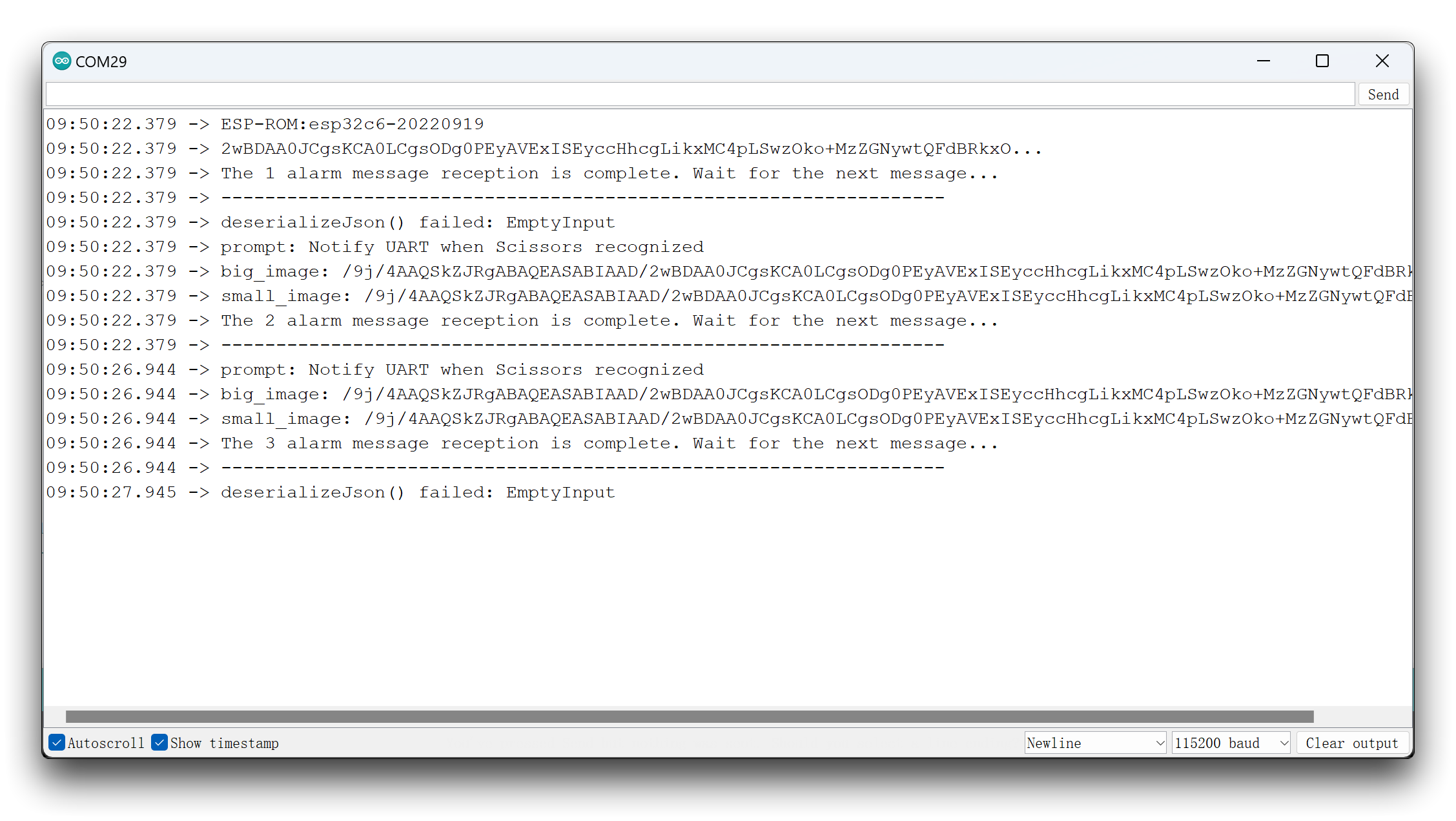
Expected Results
Once the code is uploaded and running on your XIAO ESP32 Series board, after Watcher identifies the target alarm, you should see the following behavior:
You can also try using another Arduino development board, but make sure it has enough memory.
Raspberry Pi & Watcher
Explore the process of connecting Watcher to a Raspberry Pi and utilizing Python scripts to parse and analyze the UART data.
Wiring
This section will explain the Raspberry Pi 5 as an example, if you need it, you can place an order for it through the link below.
If you are using another Raspberry Pi series, the code and tutorials on how to use it are essentially the same.
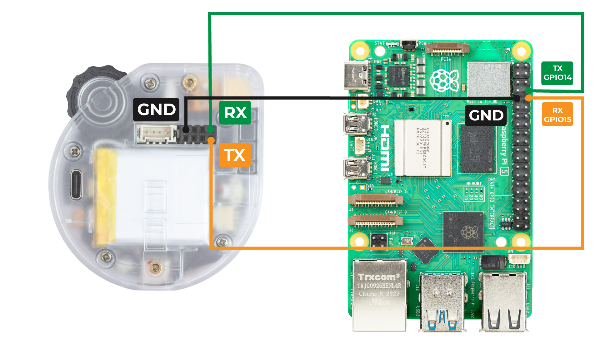
Connect the TX pin of the Watcher to the RX pin (GPIO 15) of the Raspberry Pi.
Connect the RX pin of the Watcher to the TX pin (GPIO 14) of the Raspberry Pi.
Connect the GND pin of the Watcher to a GND pin on the Raspberry Pi.
Code Explanation
Before running the Python scripts, make sure to install the required dependencies:
sudo apt update
sudo apt install python3-pip
pip3 install pyserial pillow
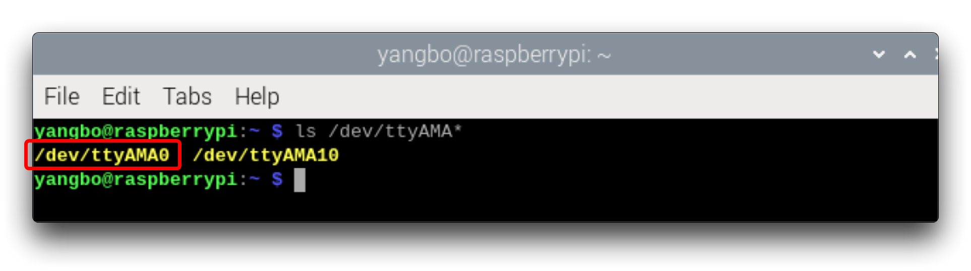
Check the device name of the UART interface on the Raspberry Pi:
ls /dev/ttyAMA*
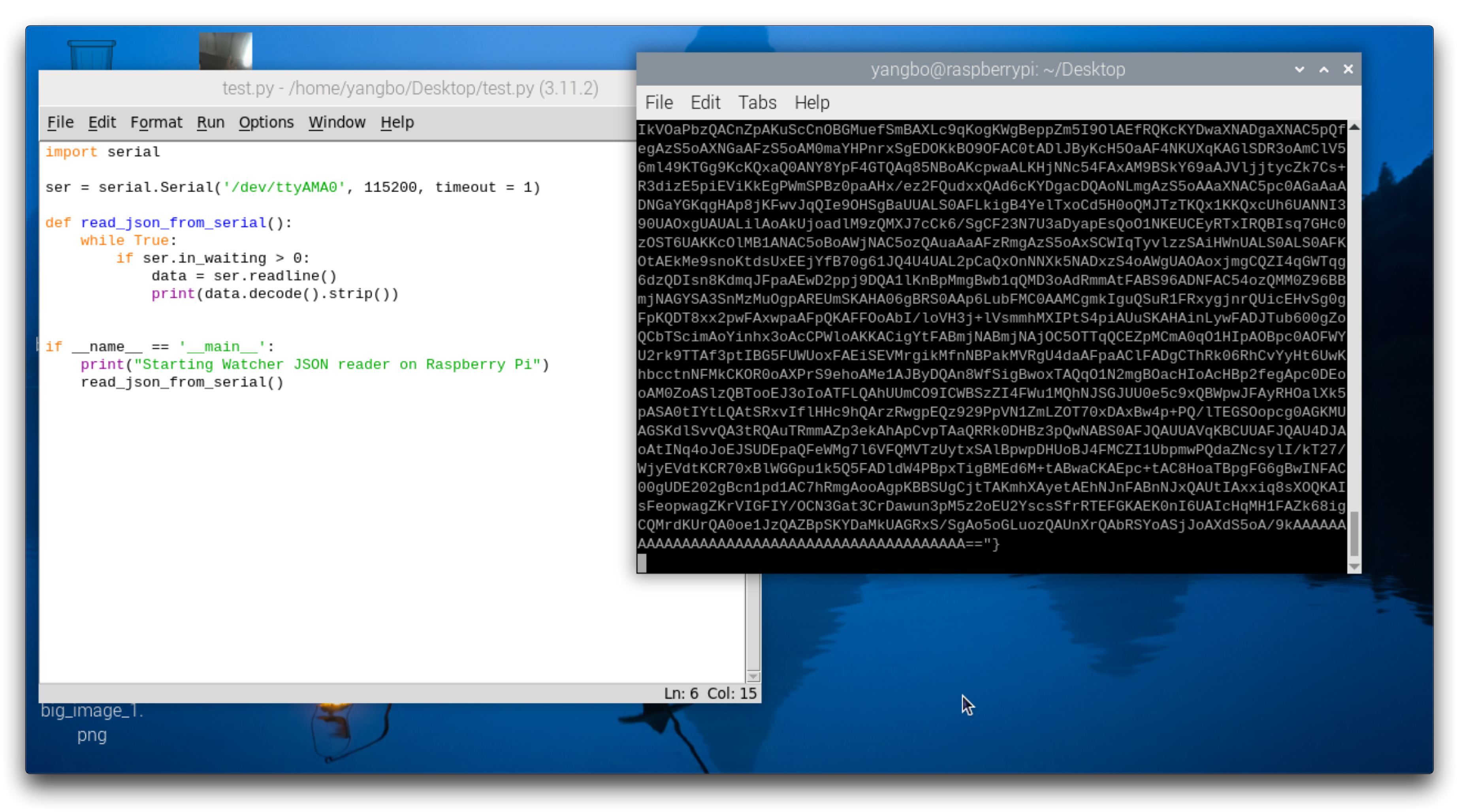
The first Python script reads the JSON data from the Watcher over UART and prints it:
import serial

# Set up the serial port
ser = serial.Serial('/dev/ttyAMA0', 115200, timeout=1)

def read_json_from_serial():
    while True:
        if ser.in_waiting > 0:
            data = ser.readline()
            print(data.decode().strip())

if __name__ == "__main__":
    print("Starting serial JSON reader on Raspberry Pi...")
    read_json_from_serial()
My UART interface corresponds to
/dev/ttyAMA0, if yours doesn't, please modify it yourself.This is a test script that you can use to check if the Raspberry Pi/Watcher's UART is working properly.
The second Python script builds upon the first one and adds JSON parsing and saving of image data:
import json
import serial
import base64
from PIL import Image
import io

# Set up the serial port
ser = serial.Serial('/dev/ttyAMA0', 115200, timeout=1)

# Initialize image counters
big_image_counter = 1
small_image_counter = 1

def read_json_from_serial():
    buffer = ""
    try:
        while True:
            if ser.in_waiting > 0:
                data = ser.read(ser.in_waiting).decode()
                buffer += data

                if '}' in buffer:
                    end = buffer.rfind('}')
                    json_data = buffer[:end+1]
                    buffer = buffer[end+1:]

                    try:
                        data = json.loads(json_data)
                        print("Received JSON data, processing...")
                        process_json_data(data)
                    except json.JSONDecodeError:
                        print("Error decoding JSON")
                        buffer = json_data + buffer
    except Exception as e:
        print(f"An error occurred: {e}")

def process_json_data(data):
    global big_image_counter, small_image_counter  # Declare global variables

    # Process prompt info
    if "prompt" in data:
        print(f"Prompt: {data['prompt']}")

    # Process boxes info
    #if "boxes" in data:
        #for index, box in enumerate(data['boxes']):
            #print(f"Box {index + 1} - x: {box['x']}, y: {box['y']}, w: {box['w']}, h: {box['h']}, score: {box['score']}, target_cls_id: {box['target_cls_id']}")

    if "big_image" in data:
        filename = f'big_image_{big_image_counter}.png'
        decode_and_save_image(data['big_image'], filename)
        print(f"Big image processed and saved as {filename}.")
        big_image_counter += 1  # Update global variable

    if "small_image" in data:
        filename = f'small_image_{small_image_counter}.png'
        decode_and_save_image(data['small_image'], filename)
        print(f"Small image processed and saved as {filename}.")
        small_image_counter += 1  # Update global variable

def decode_and_save_image(base64_data, filename):
    image_bytes = base64.b64decode(base64_data)
    image = Image.open(io.BytesIO(image_bytes))
    image.save(filename)  # Save as PNG file
    return image

if __name__ == "__main__":
    print("Starting serial JSON reader on Raspberry Pi...")
    read_json_from_serial()
Currently, only JSON data streams can be output, so only programs that parse JSON data streams are provided.
This script does the following:
Reads JSON data from UART in a loop
Decodes the JSON data and calls
process_json_datato handle itExtracts prompt info and image data from the JSON
The parsing of information about recognised boxes (boxes) is not available at the moment, because the corresponding function of Watcher is still under development, and this information is not yet reported in the latest v1.0.1 version.
Decodes the base64 encoded image data and saves as PNG files using
decode_and_save_imagePrints the extracted info and filenames of saved images
Running the Code to Raspberry Pi
- Create a new Python file on the Raspberry Pi, e.g. watcher_uart.py:
nano watcher_uart.py
Copy and paste the complete Python code into the file.
Press Ctrl+X, then Y and Enter to save and exit the editor.
Run the Python script:
python watcher_uart.py
Expected Results
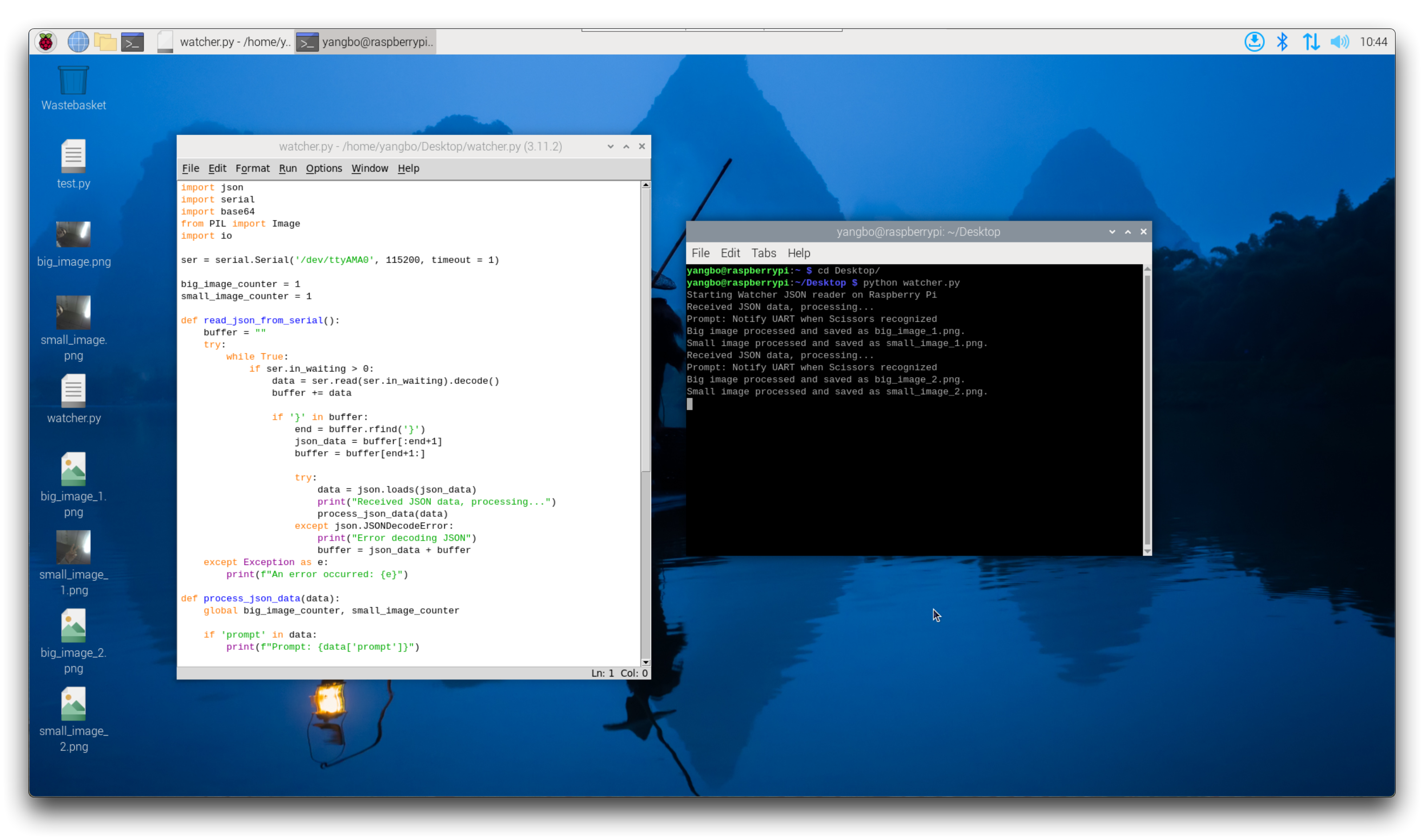
After running the script:
The parsed JSON data received from the Watcher will be printed in the terminal in real-time.
The received big image and small image will be automatically saved as big_image_x.png and small_image_x.png files.
That's it! You have now learned how to connect the Watcher to a Raspberry Pi, read the UART data with Python, parse the JSON, and save the transmitted images. Feel free to experiment further, such as trying to display the received data on a screen connected to the Raspberry Pi in real-time.
reComputer Jetson & Watch
Explore the process of connecting Watcher to a reComputer (an NVIDIA Jetson-based device) and utilizing Python scripts to parse and analyze the UART data.
Wiring
This tutorial will explain the J401 reComputer carrier board suitable for developers as an example, and if you want to buy the reComputer, you can pick it up at the link below.
In theory, the content and code in this section applies to all NVIDIA Jetson series products.
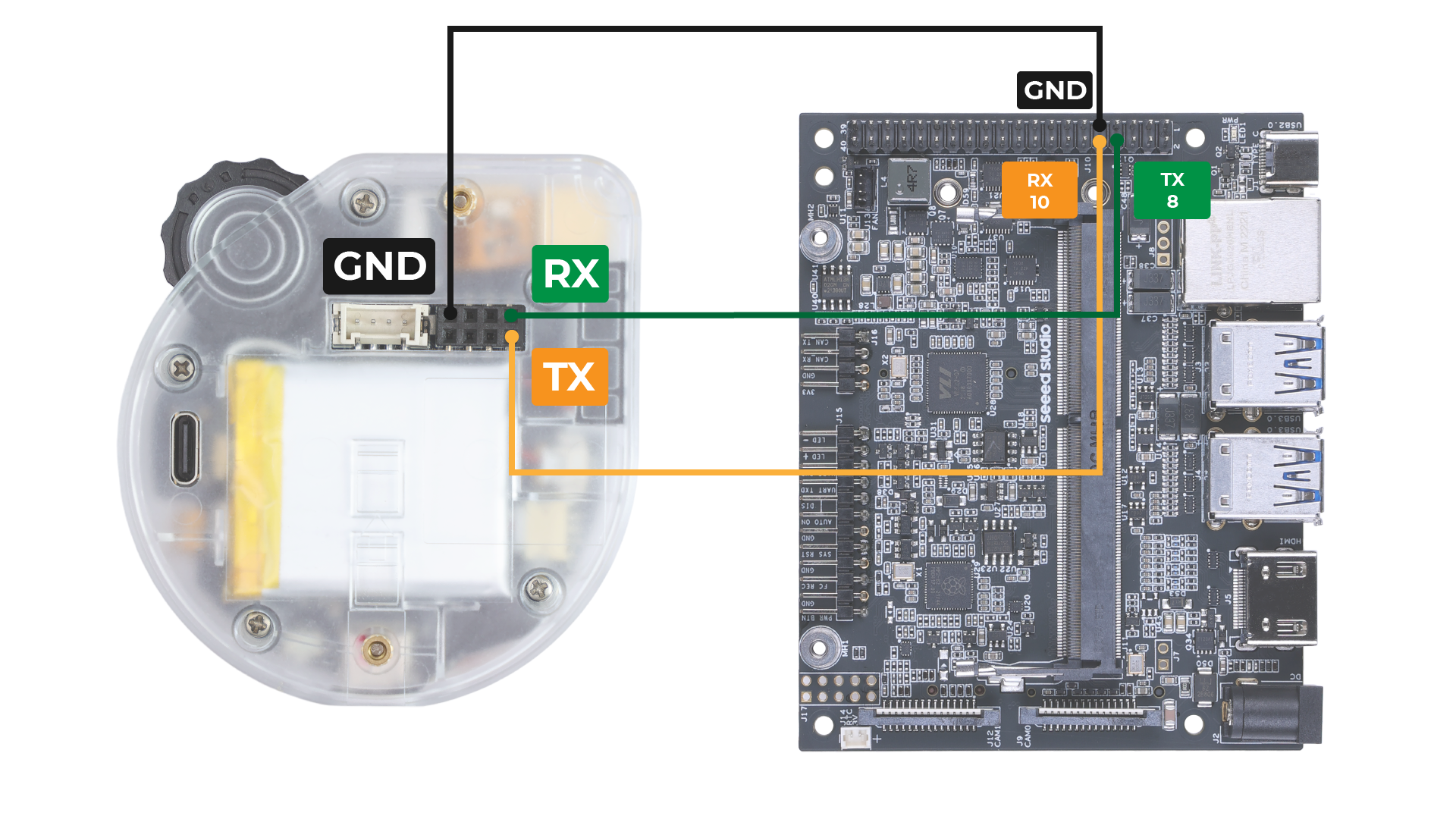
Connect the TX pin of the Watcher to the RX pin of the reComputer's UART interface.
Connect the RX pin of the Watcher to the TX pin of the reComputer's UART interface.
Connect the GND pin of the Watcher to a GND pin on the reComputer.
Code Explanation
Before running the Python scripts, make sure to install the required dependencies:
sudo apt-get update
sudo apt-get install python3-serial
sudo apt-get install python3-pillow
If you do not intend to use the Serial Console on the UART, you should disable the Serial Console:
systemctl stop nvgetty
systemctl disable nvgetty
udevadm trigger
You may need to reboot your reComputer at this point for the changes to take effect.
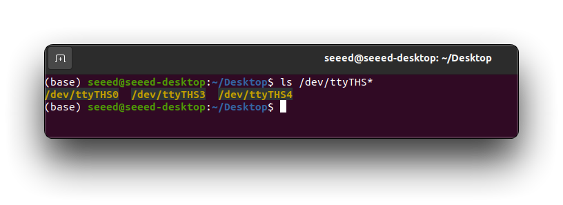
Check the device name of the UART interface on the reComputer:
ls /dev/ttyTHS*
The first Python script reads the JSON data from the Watcher over UART and prints it:
import serial

# Set up the serial port
ser = serial.Serial('/dev/ttyTHS0', 115200, timeout=1)

def read_json_from_serial():
    while True:
        if ser.in_waiting > 0:
            data = ser.readline()
            print(data.decode().strip())

if __name__ == "__main__":
    print("Starting serial JSON reader on reComputer...")
    read_json_from_serial()
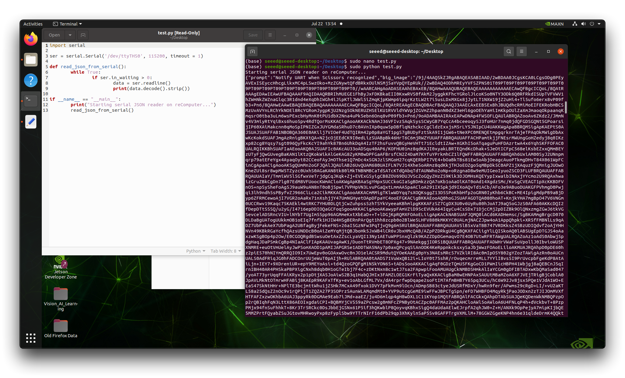
My UART interface corresponds to
/dev/ttyTHS0, if yours doesn't, please modify it yourself.This is a test script that you can use to check if the reComputer/Watcher's UART is working properly.
The second Python script builds upon the first one and adds JSON parsing and saving of image data:
import json
import serial
import base64
from PIL import Image
import io

# Set up the serial port
ser = serial.Serial('/dev/ttyTHS0', 115200, timeout=1)

# Initialize image counters
big_image_counter = 1
small_image_counter = 1

def read_json_from_serial():
    buffer = ""
    try:
        while True:
            if ser.in_waiting > 0:
                data = ser.read(ser.in_waiting).decode()
                buffer += data

                if '}' in buffer:
                    end = buffer.rfind('}')
                    json_data = buffer[:end+1]
                    buffer = buffer[end+1:]

                    try:
                        data = json.loads(json_data)
                        print("Received JSON data, processing...")
                        process_json_data(data)
                    except json.JSONDecodeError:
                        print("Error decoding JSON")
                        buffer = json_data + buffer
    except Exception as e:
        print(f"An error occurred: {e}")

def process_json_data(data):
    global big_image_counter, small_image_counter  # Declare global variables

    # Process prompt info
    if "prompt" in data:
        print(f"Prompt: {data['prompt']}")

    # Process boxes info
    #if "boxes" in data:
        #for index, box in enumerate(data['boxes']):
            #print(f"Box {index + 1} - x: {box['x']}, y: {box['y']}, w: {box['w']}, h: {box['h']}, score: {box['score']}, target_cls_id: {box['target_cls_id']}")

    if "big_image" in data:
        filename = f'big_image_{big_image_counter}.png'
        decode_and_save_image(data['big_image'], filename)
        print(f"Big image processed and saved as {filename}.")
        big_image_counter += 1  # Update global variable

    if "small_image" in data:
        filename = f'small_image_{small_image_counter}.png'
        decode_and_save_image(data['small_image'], filename)
        print(f"Small image processed and saved as {filename}.")
        small_image_counter += 1  # Update global variable

def decode_and_save_image(base64_data, filename):
    image_bytes = base64.b64decode(base64_data)
    image = Image.open(io.BytesIO(image_bytes))
    image.save(filename)  # Save as PNG file
    return image

if __name__ == "__main__":
    print("Starting serial JSON reader on reComputer...")
    read_json_from_serial()
Currently, only JSON data streams can be output, so only programs that parse JSON data streams are provided.
This script does the following:
Reads JSON data from UART in a loop
Decodes the JSON data and calls process_json_data to handle it
Extracts prompt info and image data from the JSON
Decodes the base64 encoded image data and saves as PNG files using
decode_and_save_image
The parsing of information about recognised boxes (boxes) is not available at the moment, because the corresponding function of Watcher is still under development, and this information is not yet reported in the latest v1.0.1 version.
- Prints the extracted info and filenames of saved images
Uploading the Code to reComputer
Create a new Python file on the reComputer, e.g. watcher_uart.py:
nano watcher_uart.py
Copy and paste the complete Python code into the file. Press Ctrl+X, then Y and Enter to save and exit the editor. Run the Python script:
sudo python watcher_uart.py
Expected Results
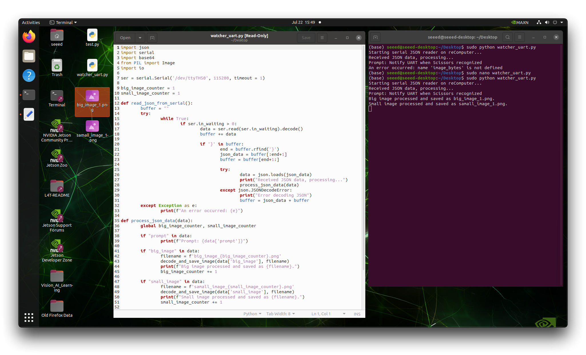
After running the script:
The parsed JSON data received from the Watcher will be printed in the terminal in real-time, including the prompt information.
The received big image and small image will be automatically saved as big_image_x.png and small_image_x.png files.
That's it! You have now learned how to connect the Watcher to a reComputer, read the UART data with Python, parse the JSON, and save the transmitted images. Feel free to experiment further and adapt the code to your specific use case on the reComputer platform.
Resources
Watcher Quick Start Series 1# : How to assign tasks to Watcher
Watcher Quick Start Series 2# : Watcher Looks & SenseCraft Tools
Watcher Quick Start Series 4# : Deploy Watcher's AI capabilities locally
Watcher Quick Start Series 5# : Training a model for Watcher
Tech Support & Product Discussion
Thank you for choosing our products! We are here to provide you with different support to ensure that your experience with our products is as smooth as possible. We offer several communication channels to cater to different preferences and needs.