Getting Started with Seeed Studio XIAO ESP32C6
| Seeed Studio XIAO ESP32C6 |
|---|
 |
Introduction
Seeed Studio XIAO ESP32C6 is powered by the highly-integrated ESP32-C6 SoC, built on two 32-bit RISC-V processors, with a high-performance (HP) processor with running up to 160 MHz, and a low-power (LP) 32-bit RISC-V processor, which can be clocked up to 20 MHz. There are 512KB SRAM and 4 MB Flash on the chip, allowing for more programming space, and binging more possibilities to the IoT control scenarios.
XIAO ESP32C6 is Matter native thanks to its enhanced wireless connectivity. The wireless stack supports 2.4 GHz WiFi 6, Bluetooth® 5.3, Zigbee, and Thread (802.15.4). As the first XIAO member compatible with Thread, it's a perfect fit for building Matter-compliant projects, thus achieving interoperability in smart-home.
Specifications
| Product | XIAO ESP32-C6 | XIAO ESP32-C3 | XIAO ESP32-S3 |
|---|---|---|---|
| Processor | Espressif ESP32-C6 SoC two 32-bit RISC-V processors, with the high-performance one running up to 160 MHz, and the low-power one clocking up to 20 MHz | Espressif ESP32-C3 SoC RISC-V single-core 32-bit chip processor with a four-stage pipeline that operates at up to 160 MHz | Espressif ESP32-S3R8 SoC Xtensa LX7 dual-core, 32-bit processor running up to 240 MHz |
| Wireless | Complete 2.4GHz Wi-Fi 6 subsystem | Complete 2.4GHz Wi-Fi subsystem | Complete 2.4GHz Wi-Fi subsystem |
| Bluetooth Low Energy 5.0 | |||
| Zigbee, Thread, IEEE 802.15.4 | / | / | |
| On-chip Memory | 512KB SRAM & 4MB Flash | 400KB SRAM & 4MB Flash | 8MB PSRAM & 8MB Flash |
| Interface | 1x UART 1x LP_UART 1x IIC 1x LP_IIC 1x SPI 11x GPIO(PWM) 7x ADC 1x SDIO | 1x UART 1x IIC 1x SPI 11x GPIO(PWM) 4x ADC | 1x UART 1x IIC 1x SPI 11x GPIO(PWM) 9x ADC 1x User LED 1x Charge LED |
| 1x Reset button 1x Boot button | |||
| Dimensions | 21 x 17.8mm | ||
| Power | Input voltage (Type-C): 5V Input voltage (BAT): 3.7V | ||
| Power Consumption Model (Typ.) (Supply Power: 3.8V) | Modem-sleep Model: 30 mA Light-sleep Model: 3.1 mA Deep Sleep Model: 15 μA | Modem-sleep Model: 24 mA Light-sleep Model: 3 mA Deep Sleep Model: 44 μA | Modem-sleep Model: 27 mA Light-sleep Model: 2 mA Deep Sleep Model: 14 μA |
| Working Temperature | -40°C ~ 85°C | -40°C ~ 85°C | -40°C ~ 65°C |
XIAO ESP32-S3 vs ESP32-C3 vs ESP32-C6: Which One Is Best for Your Project?
Features
- Enhanced Connectivity: Integrates 2.4 GHz Wi-Fi 6 (802.11ax), Bluetooth 5(LE), and IEEE 802.15.4 radio connectivity, allowing for the application of Thread and Zigbee protocols.
- Matter Native: Supports the building of Matter-compliant smart home projects, ensuring interoperability among different smart devices.
- Security Encrypted on Chip: Utilizes the ESP32-C6 to provide secure boot, encryption, and Trusted Execution Environment (TEE) features, enhancing the security of smart home projects.
- Outstanding RF Performance: Features an on-board antenna with up to 80m BLE/Wi-Fi range and offers an interface for connecting an external UFL antenna, ensuring reliable connectivity.
- Leveraging Power Consumption: Offers four working modes, including a deep sleep mode with consumption as low as 15 μA, along with support for lithium battery charge management.
- Dual RISC-V Processors: Incorporates two 32-bit RISC-V processors, with the high-performance processor capable of running up to 160 MHz and the low-power processor up to 20 MHz.
- Classic XIAO Designs: Maintains the thumb-size form factor of 21 x 17.8mm and single-sided mount design, ideal for space-limited projects like wearable devices.
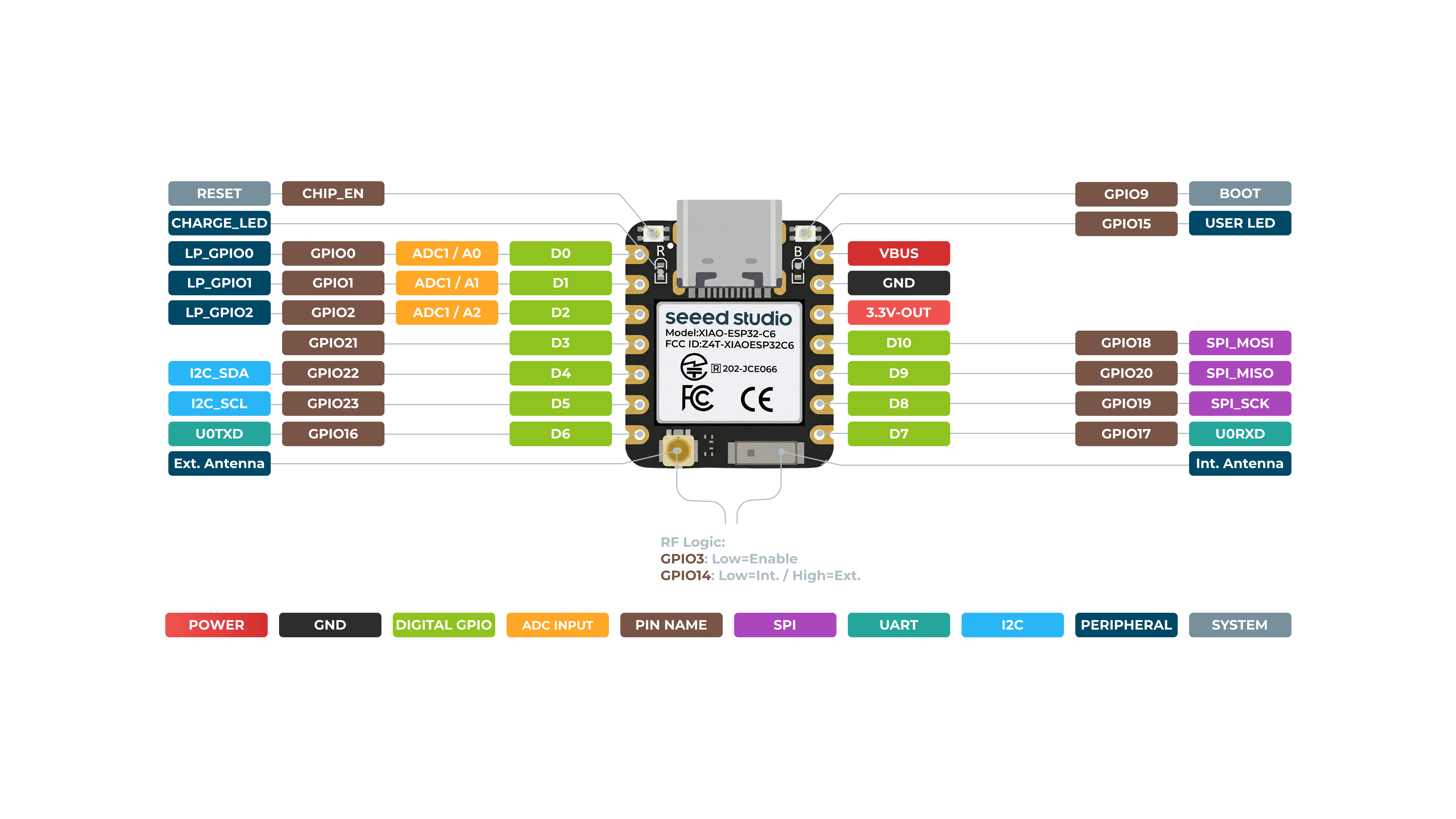
Hardware overview
Front
Back
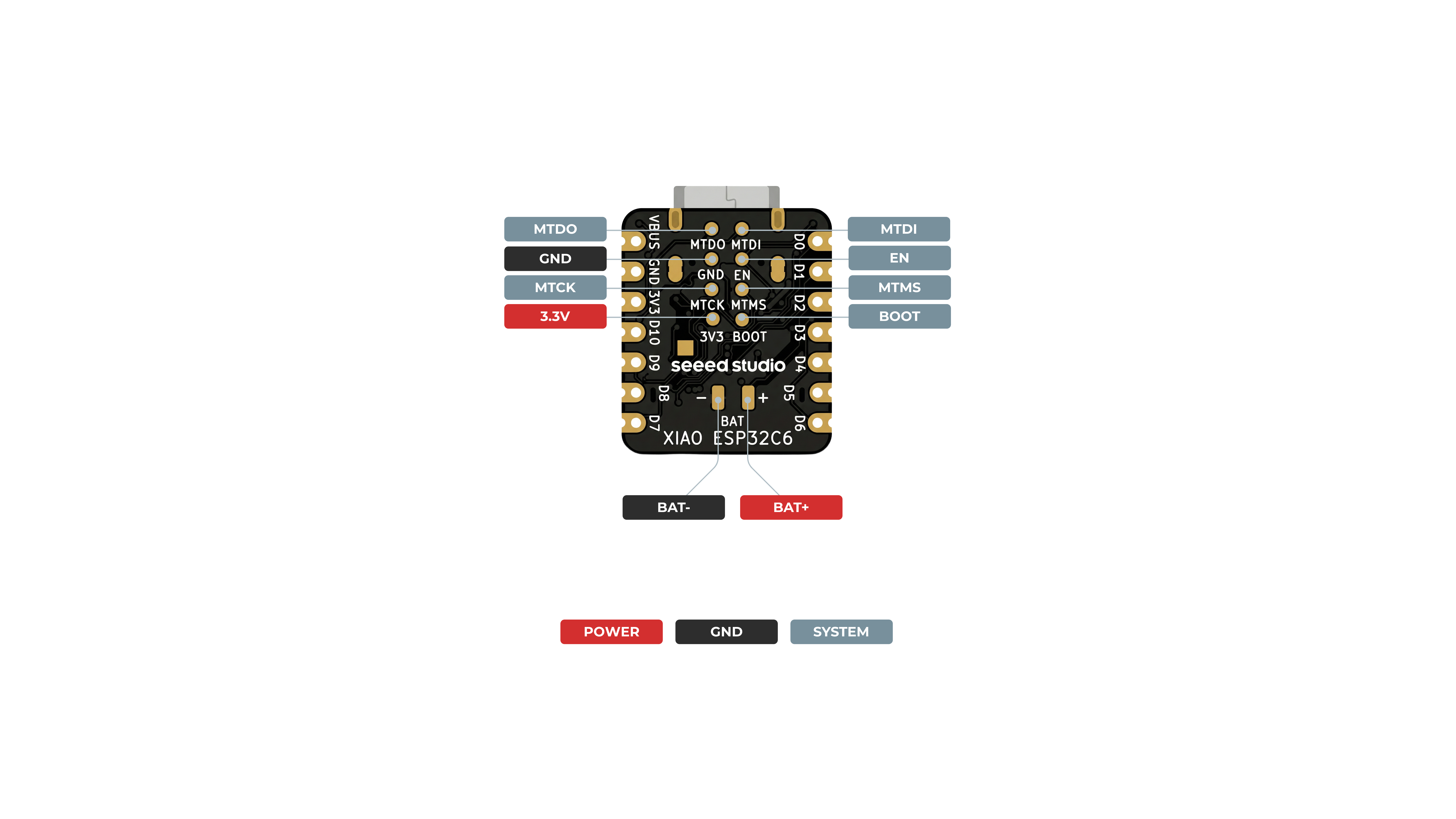
The RF Switch feature allows you to toggle between the built-in ceramic antenna and an external antenna by configuring GPIO14. To enable this function, you must first set GPIO3 to a low level, as this activates the RF switch control.
- GPIO14 Low Level (Default Setting): The device uses the built-in ceramic antenna.
- GPIO14 High Level: The device switches to the external antenna.
By default, GPIO14 is set to a low level, enabling the built-in antenna. To use an external antenna, set GPIO14 to a high level. Refer to the example code below for guidance on configuring GPIO3 and GPIO14 to activate the external antenna:
void setup() {
  pinMode(WIFI_ENABLE, OUTPUT); // pinMode(3, OUTPUT);
  digitalWrite(WIFI_ENABLE, LOW); // digitalWrite(3, LOW); // Activate RF switch control

  delay(100);

  pinMode(WIFI_ANT_CONFIG, OUTPUT); // pinMode(14, OUTPUT);
  digitalWrite(WIFI_ANT_CONFIG, HIGH); // digitalWrite(14, HIGH); // Use external antenna
}
Pin Map
| XIAO Pin | Function | Chip Pin | Alternate Functions | Description |
|---|---|---|---|---|
| 5V | VBUS | Power Input/Output | ||
| GND | ||||
| 3V3 | 3V3_OUT | Power Output | ||
| D0 | Analog | GPIO0 | LP_GPIO0 | GPIO, ADC |
| D1 | Analog | GPIO1 | LP_GPIO1 | GPIO, ADC |
| D2 | Analog | GPIO2 | LP_GPIO2 | GPIO, ADC |
| D3 | Digital | GPIO21 | SDIO_DATA1 | GPIO |
| D4 | SDA | GPIO22 | SDIO_DATA2 | GPIO, I2C Data |
| D5 | SCL | GPIO23 | SDIO_DATA3 | GPIO, I2C Clock |
| D6 | TX | GPIO16 | GPIO, UART Transmit | |
| D7 | RX | GPIO17 | GPIO, UART Receive | |
| D8 | SCK | GPIO19 | SPI_CLK | GPIO, SPI Clock |
| D9 | MISO | GPIO20 | SPI_MISO | GPIO, SPI Data |
| D10 | MOSI | GPIO18 | SPI_MOSI | GPIO, SPI Data |
| MTDO | GPIO7 | JTAG | ||
| MTDI | GPIO5 | JTAG, ADC | ||
| MTCK | GPIO6 | JTAG, ADC | ||
| MTMS | GPIO4 | JTAG, ADC | ||
| EN | CHIP_PU | Reset | ||
| Boot | GPIO9 | Enter Boot Mode | ||
| RF Switch Port Select | GPIO14 | Switch onboard antenna and the UFL antenna | ||
| RF Switch Power | GPIO3 | Power | ||
| Light | GPIO15 | User Light |
Getting started
To enable you to get started with the XIAO ESP32C6 faster, please read the hardware and software preparation below to prepare the XIAO.
Hardware Preparation
You need to prepare the following:
- 1 x Seeed Studio XIAO ESP32C6
- 1 x Computer
- 1 x USB Type-C cable
Some USB cables can only supply power and cannot transfer data. If you don't have a USB cable or don't know if your USB cable can transmit data, you can check Seeed USB Type-C support USB 3.1.
Solder header
XIAO ESP32C6 is shipped without pin headers by default, you need to prepare your own pin headers and solder it to the corresponding pins of XIAO so that you can connect to the expansion board or sensor.
Due to the miniature size of XIAO ESP32C6, please be careful when soldering headers, do not stick different pins together, and do not stick solder to the shield or other components. Otherwise, it may cause XIAO to short circuit or not work properly, and the consequences caused by this will be borne by the user.
BootLoader Mode
There are times when we use the wrong program to make XIAO appear to lose ports or not work properly. The specific performance is:
- Connected to computer, but no port number found for XIAO.
- The computer is connected and the port number appears, but the upload program fails.
When you encounter the above two situations, you can try to put XIAO into BootLoader mode, which can solve most of the problems of unrecognized devices and failed uploads. The specific method is:
- Step 1. Press and hold the BOOT button on the XIAO ESP32C6 without releasing it.
- Step 2. Keep the BOOT button pressed and then connect to the computer via the data cable. Release the BOOT button after connecting to the computer.
- Step 3. Upload the Blink program to check the operation of the XIAO ESP32C6.
Reset
When the program runs abnormally, you can press Reset once during power-up to let XIAO re-execute the uploaded program.
When you press and hold the BOOT key while powering up and then press the Reset key once, you can also enter BootLoader mode.
Software Preparation
The recommended programming tool for the XIAO ESP32C6 is the Arduino IDE, so you need to complete the Arduino installation as part of the software preparation.
If this is your first time using Arduino, we highly recommend you to refer to Getting Started with Arduino.
And the on-board package for XIAO ESP32C6 requires at least version 2.0.8 to be available.
-
Step 1. Download and Install the stable version of Arduino IDE according to your operating system.
-
Step 2. Launch the Arduino application.
-
Step 3. Add the XIAO ESP32C6 on-board package to the Arduino IDE and click
OK. -
Step 4. Close the Arduino IDE and reopen it.
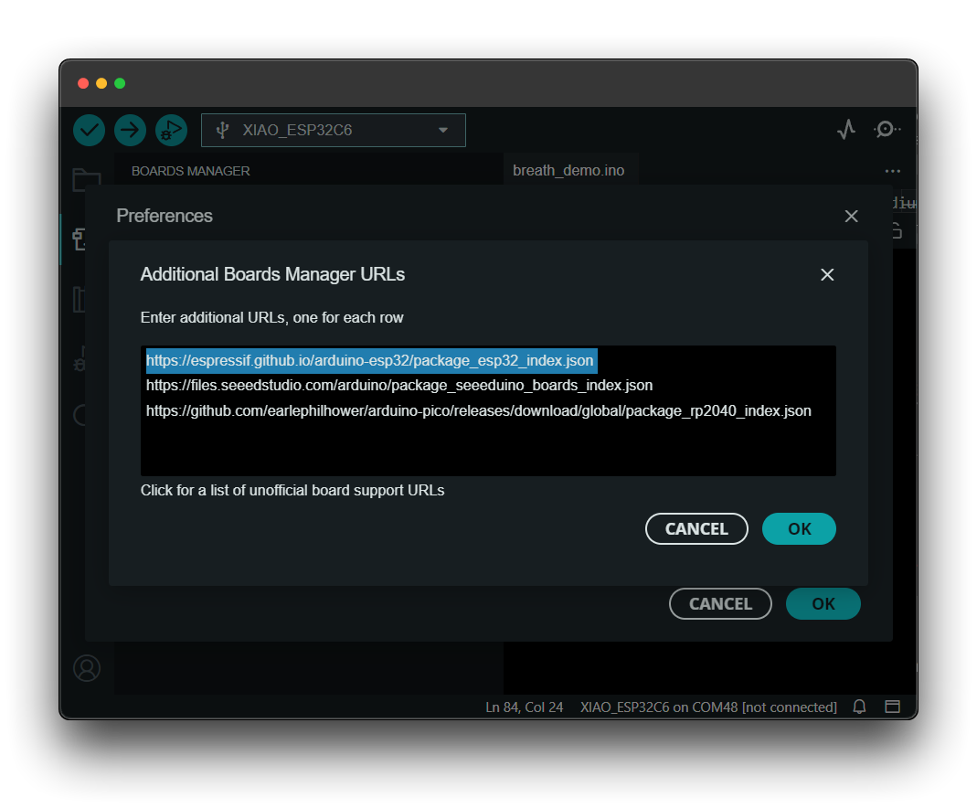
Add the XIAO-C6 Board
To install the XIAO ESP32C6 board, follow these steps:
https://espressif.github.io/arduino-esp32/package_esp32_index.json
- Add the above board manager URL to the preferences of your Arduino IDE, which is taken from the Installing - Arduino ESP32.
- Download the XIAO ESP32C6 board package.
Only available if the version of the esp32 board is greater than 3.0.0.
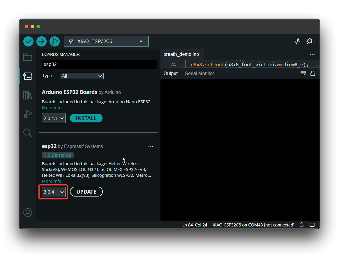
- Opt for
XIAO_ESP32C6variant.
Now enjoy coding ✨.
Run your first Blink program
-
Step 1. Launch the Arduino application.
-
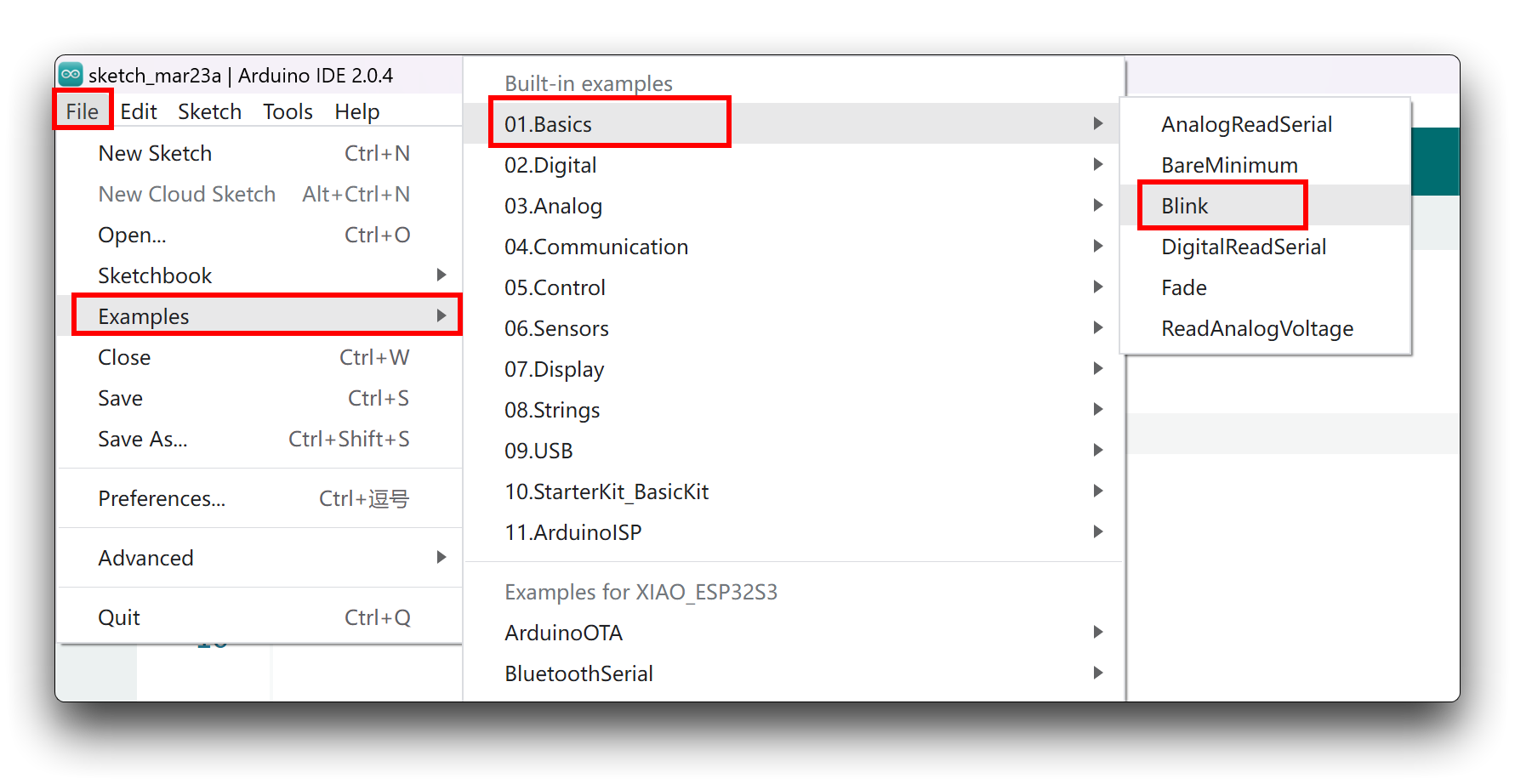
Step 2. Navigate to File > Examples > 01.Basics > Blink, open the program.
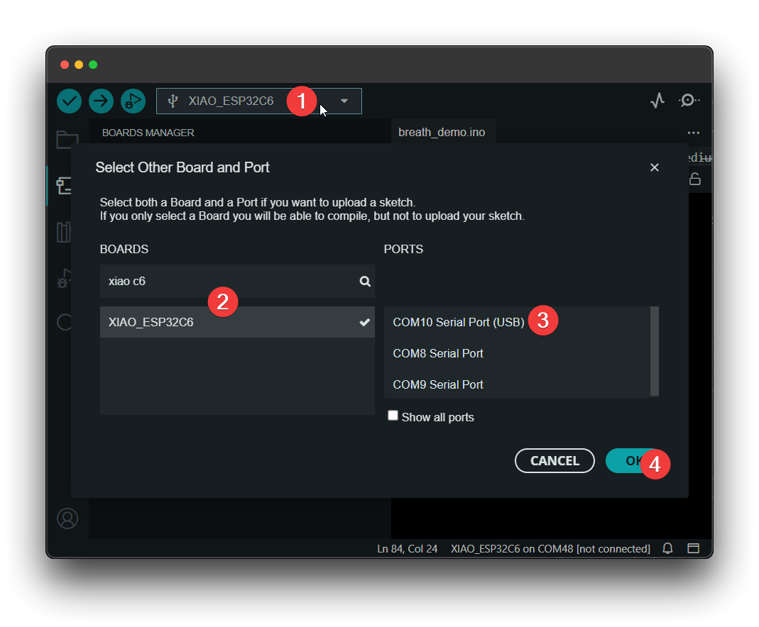
- Step 3. Select the board model to XIAO ESP32C6, and select the correct port number to upload the program.
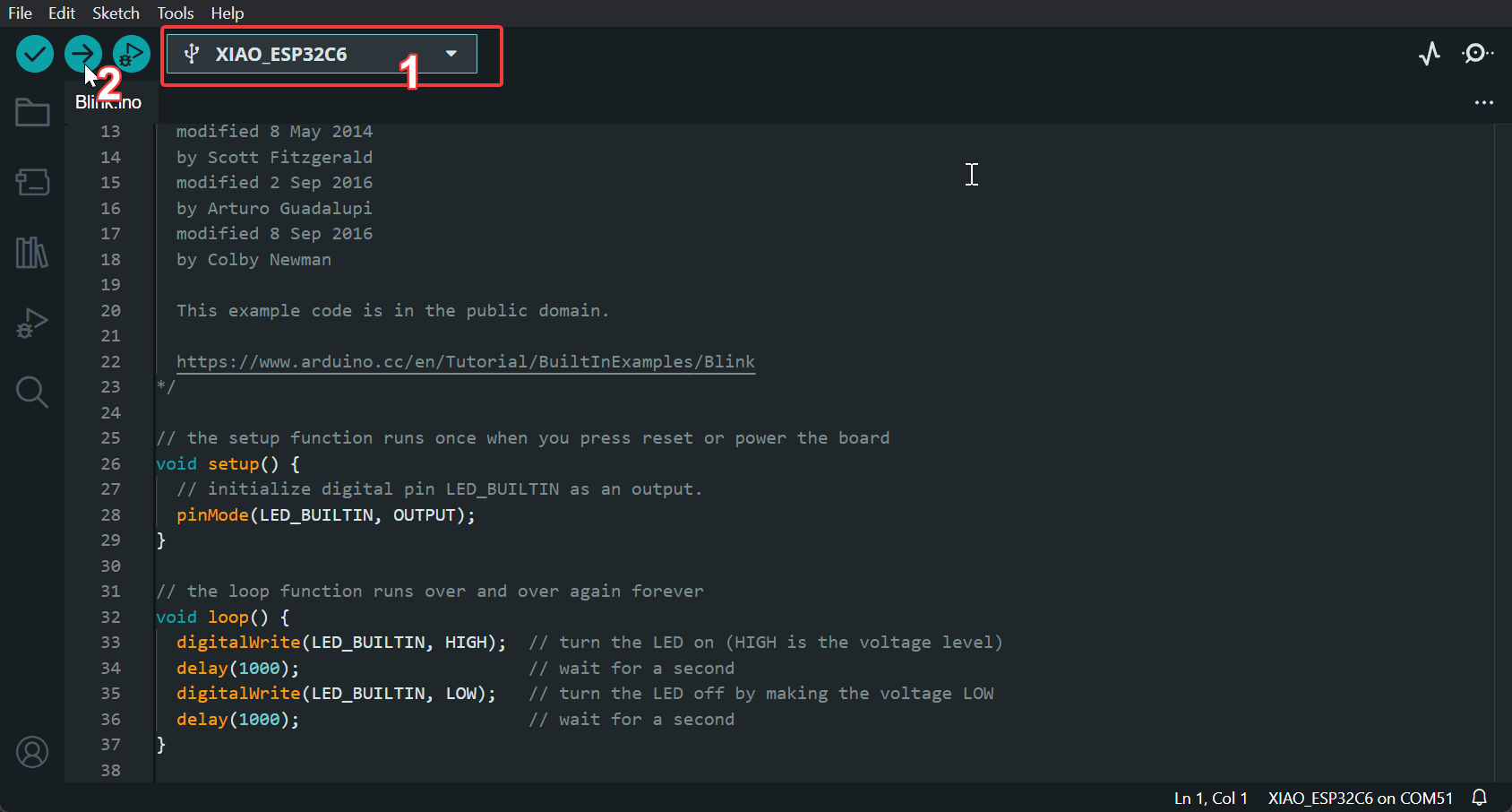
Once the program is successfully uploaded, you will see the following output message and you can observe that the orange LED on the right side of the XIAO ESP32C6 is blinking.
 |  |
Battery Usage
The XIAO ESP32C6 series features a built-in power management chip, allowing it to be powered independently by a battery or to charge the battery through its USB port.
For connecting a battery to your XIAO, we recommend using a qualified rechargeable 3.7V lithium battery. When soldering the battery, carefully distinguish between the positive and negative terminals. The negative electrode pad should be located on the left side near the silk screen marking "D8," while the positive electrode pad should be located on the right side near the silk screen marking "D5."
When using battery power, no voltage will be present on the 5V pin.
The XIAO ESP32C6 has a red indicator light for battery charging, similar to the XIAO ESP32S3:
The red light behavior for the XIAO ESP32C6 is as follows:
- When no battery is connected:
- The red light turns on when the Type-C cable is connected and turns off after 30 seconds.
- When a battery is connected and the Type-C cable is plugged in for charging:
- The red light flashes.
- When the battery is fully charged via the Type-C connection:
- The red light turns off.
Reading Battery Voltage
To monitor the battery voltage on the XIAO ESP32C6, similar to the XIAO ESP32C3, you'll need to solder a 200k resistor in a 1:2 configuration. This setup reduces the voltage by half, allowing safe monitoring through the A0 analog port.
Sample Code
The code below initializes the ADC on the A0 port and averages 16 readings to calculate the battery voltage, adjusting for the 1:2 attenuation ratio of the voltage divider.
#include <Arduino.h>

void setup() {
  Serial.begin(115200);
  pinMode(A0, INPUT);         // Configure A0 as ADC input
}

void loop() {
  uint32_t Vbatt = 0;
  for(int i = 0; i < 16; i++) {
    Vbatt += analogReadMilliVolts(A0); // Read and accumulate ADC voltage
  }
  float Vbattf = 2 * Vbatt / 16 / 1000.0;     // Adjust for 1:2 divider and convert to volts
  Serial.println(Vbattf, 3);                  // Output voltage to 3 decimal places
  delay(1000);                                // Wait for 1 second
}
This code takes 16 measurements from the ADC, averages them, and then compensates for the voltage divider's 1:2 ratio to output the battery voltage in volts with three decimal places of precision.
Deep sleep mode and wake-up
The XIAO ESP32C6 has a complete deep sleep mode and wake-up function. Here we will show two of the more common examples offered by the ESP.
Demo1: Deep Sleep with External Wake Up
This code displays how to use deep sleep with an external trigger as a wake up source and how to store data in RTC memory to use it over reboots.
/*
Hardware Connections
======================
Push Button to GPIO 0 pulled down with a 10K Ohm
resistor

NOTE:
======
Bit mask of GPIO numbers which will cause wakeup. Only GPIOs
which have RTC functionality can be used in this bit map.
For different SoCs, the related GPIOs are:
- ESP32: 0, 2, 4, 12-15, 25-27, 32-39
- ESP32-S2: 0-21
- ESP32-S3: 0-21
- ESP32-C6: 0-7
- ESP32-H2: 7-14
*/

#define BUTTON_PIN_BITMASK (1ULL << GPIO_NUM_0) // GPIO 0 bitmask for ext1

RTC_DATA_ATTR int bootCount = 0;

/*
Method to print the reason by which ESP32
has been awaken from sleep
*/
void print_wakeup_reason(){
  esp_sleep_wakeup_cause_t wakeup_reason;

  wakeup_reason = esp_sleep_get_wakeup_cause();

  switch(wakeup_reason)
  {
    case ESP_SLEEP_WAKEUP_EXT0 : Serial.println("Wakeup caused by external signal using RTC_IO"); break;
    case ESP_SLEEP_WAKEUP_EXT1 : Serial.println("Wakeup caused by external signal using RTC_CNTL"); break;
    case ESP_SLEEP_WAKEUP_TIMER : Serial.println("Wakeup caused by timer"); break;
    case ESP_SLEEP_WAKEUP_TOUCHPAD : Serial.println("Wakeup caused by touchpad"); break;
    case ESP_SLEEP_WAKEUP_ULP : Serial.println("Wakeup caused by ULP program"); break;
    default : Serial.printf("Wakeup was not caused by deep sleep: %d\n",wakeup_reason); break;
  }
}

void setup(){
  Serial.begin(115200);
  delay(1000); //Take some time to open up the Serial Monitor

  //Increment boot number and print it every reboot
  ++bootCount;
  Serial.println("Boot number: " + String(bootCount));

  //Print the wakeup reason for ESP32
  print_wakeup_reason();

  /*
  First we configure the wake up source
  We set our ESP32 to wake up for an external trigger.
  There are two types for ESP32, ext0 and ext1, ext0
  don't support ESP32C6 so we use ext1.
  */

  //If you were to use ext1, you would use it like
  esp_sleep_enable_ext1_wakeup(BUTTON_PIN_BITMASK,ESP_EXT1_WAKEUP_ANY_HIGH);

  //Go to sleep now
  Serial.println("Going to sleep now");
  esp_deep_sleep_start();
  Serial.println("This will never be printed");
}

void loop(){
  //This is not going to be called
}
Demo2: Deep Sleep with Timer Wake Up
ESP32 offers a deep sleep mode for effective power saving as power is an important factor for IoT applications. In this mode CPUs, most of the RAM, and all the digital peripherals which are clocked from APB_CLK are powered off. The only parts of the chip which can still be powered on are: RTC controller, RTC peripherals ,and RTC memories.
This code displays the most basic deep sleep with a timer to wake it up and how to store data in RTC memory to use it over reboots.
/*
Simple Deep Sleep with Timer Wake Up
=====================================
This code is under Public Domain License.

Author:
Pranav Cherukupalli <[email protected]>
*/

#define uS_TO_S_FACTOR 1000000ULL  /* Conversion factor for micro seconds to seconds */
#define TIME_TO_SLEEP  5        /* Time ESP32 will go to sleep (in seconds) */

RTC_DATA_ATTR int bootCount = 0;

/*
Method to print the reason by which ESP32
has been awaken from sleep
*/
void print_wakeup_reason(){
  esp_sleep_wakeup_cause_t wakeup_reason;

  wakeup_reason = esp_sleep_get_wakeup_cause();

  switch(wakeup_reason)
  {
    case ESP_SLEEP_WAKEUP_EXT0 : Serial.println("Wakeup caused by external signal using RTC_IO"); break;
    case ESP_SLEEP_WAKEUP_EXT1 : Serial.println("Wakeup caused by external signal using RTC_CNTL"); break;
    case ESP_SLEEP_WAKEUP_TIMER : Serial.println("Wakeup caused by timer"); break;
    case ESP_SLEEP_WAKEUP_TOUCHPAD : Serial.println("Wakeup caused by touchpad"); break;
    case ESP_SLEEP_WAKEUP_ULP : Serial.println("Wakeup caused by ULP program"); break;
    default : Serial.printf("Wakeup was not caused by deep sleep: %d\n",wakeup_reason); break;
  }
}

void setup(){
  Serial.begin(115200);
  delay(1000); //Take some time to open up the Serial Monitor

  //Increment boot number and print it every reboot
  ++bootCount;
  Serial.println("Boot number: " + String(bootCount));

  //Print the wakeup reason for ESP32
  print_wakeup_reason();

  /*
  First we configure the wake up source
  We set our ESP32 to wake up every 5 seconds
  */
  esp_sleep_enable_timer_wakeup(TIME_TO_SLEEP * uS_TO_S_FACTOR);
  Serial.println("Setup ESP32 to sleep for every " + String(TIME_TO_SLEEP) +
  " Seconds");

  /*
  Next we decide what all peripherals to shut down/keep on
  By default, ESP32 will automatically power down the peripherals
  not needed by the wakeup source, but if you want to be a poweruser
  this is for you. Read in detail at the API docs
  http://esp-idf.readthedocs.io/en/latest/api-reference/system/deep_sleep.html
  Left the line commented as an example of how to configure peripherals.
  The line below turns off all RTC peripherals in deep sleep.
  */
  //esp_deep_sleep_pd_config(ESP_PD_DOMAIN_RTC_PERIPH, ESP_PD_OPTION_OFF);
  //Serial.println("Configured all RTC Peripherals to be powered down in sleep");

  /*
  Now that we have setup a wake cause and if needed setup the
  peripherals state in deep sleep, we can now start going to
  deep sleep.
  In the case that no wake up sources were provided but deep
  sleep was started, it will sleep forever unless hardware
  reset occurs.
  */
  Serial.println("Going to sleep now");
  Serial.flush();
  esp_deep_sleep_start();
  Serial.println("This will never be printed");
}

void loop(){
  //This is not going to be called
}
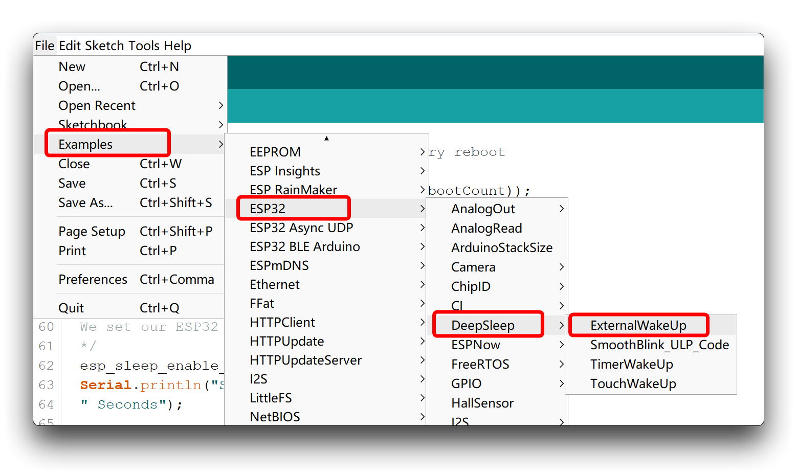
If you want to learn to use more of the deep sleep mode and wake-up functions, you can find more sample programs officially written for the chip by ESP in the Arduino IDE.
Resources
Hardware Design
- 📄[Datasheet] Espressif ESP32-C6 Datasheet
- 📄[Schematic] XIAO ESP32-C6 Schematic
- 🗃️[PCB Design Files] XIAO ESP32-C6 KiCad Project
- 🗃️[PCB Design Libraries]
- 📄[Pinout Diagram] XIAO ESP32-C6 Pinout Sheet
Mechanical Design
- 📄[3D Model] XIAO ESP32-C6 3D Model
Course Resources

Tech Support & Product Discussion
Thank you for choosing our products! We are here to provide you with different support to ensure that your experience with our products is as smooth as possible. We offer several communication channels to cater to different preferences and needs.