XIAO RP2040 With Zephyr(RTOS)
This wiki covers Zephyr support for the Seeed Studio XIAO RP2040. With the assistance of this guide you will be able to utilize the feature set available to the board.
What is Zephyr
The Zephyr OS is based on a small-footprint kernel designed for use on resource-constrained and embedded systems: from simple embedded environmental sensors and LED wearables to sophisticated embedded controllers, smart watches, and IoT wireless applications.
For each supported device Zephyr has a devicetree file that describes the board and its features. The Xiao RP2040 Zephyr board page describes the supported features currently available which is defined by the board's dts file.
Reference: Zephyr Project
Getting Started
The first step to working with Zephyr is to get the SDK and toolchain setup for local development. The Zephyr getting started guide should be referenced for the associated setup procedure needed for your environment.
Once the Zephyr toolchain has been setup and an associated SDK has been downloaded you can begin application development.
For the Xiao RP2040 the board description file can be referenced for further setup information.
To program the Xiao RP2040 the following steps can be taken:
- Build an example or your application
- Plugin the Xiao RP2040
- Hold the button designated
B(boot) and pressR(reset) which will mount the device as a mass storage device - Drag the uf2 file (ie
build/zephyr/zephyr.uf2) generated during the build process to the device triggering an update
The simplest example is to run the "Hello World" sample on the board. After changing to the directory of the Zephyr install run the following commands.
west build -p always -b xiao_rp2040 samples/subsys/usb/console
After this completes enter the build/zephyr folder and drag zephyr.uf2 to your waiting RP2040 mounted drive. The device will reset after it receives the file and your machine should now be connected over USB for serial.
Find the port for your device by typing ls /dev/tty* and confirming which device appears when your USB has been plugged in.
In my example I see /dev/ttyACM0 as the newly added device.
Using screen you can then connect and monitor the serial response:
screen /dev/ttyACM0 115200
You should see a response similar to the following:
*** Booting Zephyr OS build v3.6.0-2212-gc38ea288eee9 ***
Hello World! arm
Hello World! arm
Hello World! arm
To assist with the process of using Zephyr with Xiao and its expansion board a repository has been constructed with several overlays and configurations used here. The commands included in this wiki article assume it is located ../applications/xiao-zephyr-examples relative to the zephyr root. An alternative path can be provided to the commands below by updating it.
git clone https://github.com/Cosmic-Bee/xiao-zephyr-examples
Hardware Preparation
| Seeed Studio XIAO RP2040 | Seeed Studio Expansion Board |
|---|---|
 |  |
Developer Knowledge
XIAO Expansion Board
In order to use Grove modules with Seeed Studio XIAO RP2040, we will use a Seeed Studio Expansion Base for XIAO and connect XIAO RP2040 on it.
After that, the Grove connectors on the board can be used to connect Grove modules
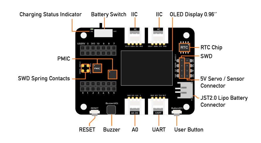
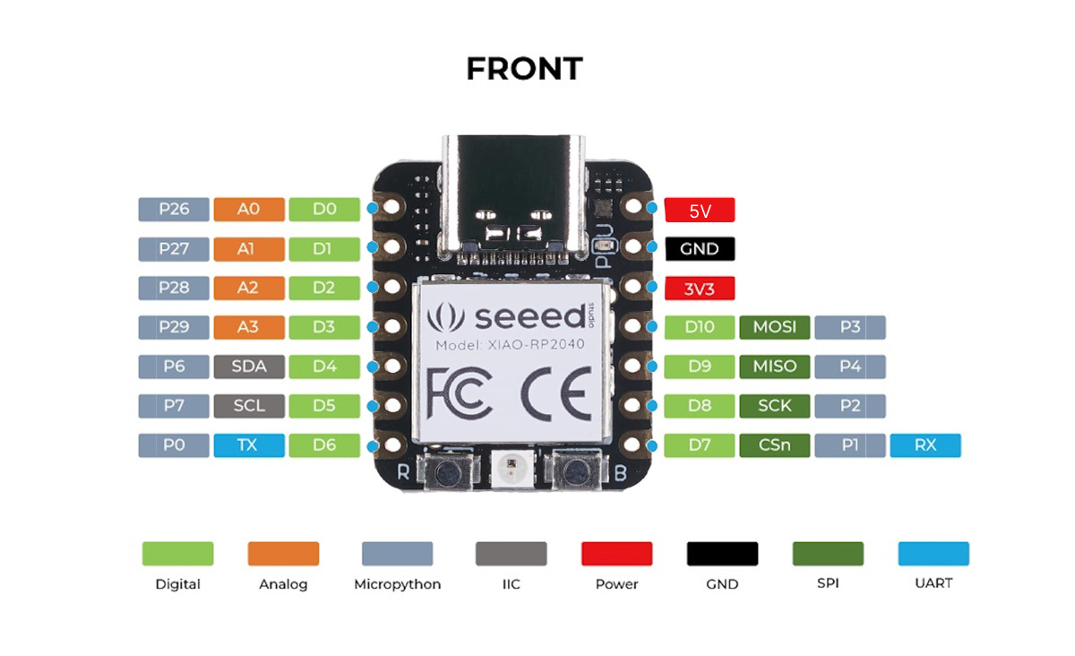
Pin Definitions
You need to follow the graphic below to use the appropriate internal pin numbers when connecting the Grove modules to the Grove connectors on Grove Shield for Seeed Studio XIAO.
Primary Functionality
- WS2812 LED
- LED PWM
- Clock
- TFLite
WS2812 LED
For this example the Xiao RP2040 utilizes its onboard LED and flashes through red, green, and blue continually.
To test this setup we can use an existing sample with Zephyr:
cd ~/zephyrproject/zephyr
west build -p always -b xiao_rp2040 samples/drivers/led_strip
You'll see the onboard WS2812 LED cycling through red, blue and green continually in a flashing pattern.
Let's dive into this example a bit to see why it works:
 / {
     aliases {
         led-strip = &ws2812;
     };
 }
 &gpio0 {
     status = "okay";
     neopixel-power-enable {
        gpio-hog;
        gpios = <11 GPIO_ACTIVE_HIGH>;
        output-high;
    };
 };
 &pio0 {
     status = "okay";

     pio-ws2812 {
         compatible = "worldsemi,ws2812-rpi_pico-pio";
         status = "okay";
         pinctrl-0 = <&ws2812_pio0_default>;
         pinctrl-names = "default";
         bit-waveform = <3>, <3>, <4>;

         ws2812: ws2812 {
             status = "okay";
             gpios = <&gpio0 12 GPIO_ACTIVE_HIGH>;
             chain-length = <1>;
             color-mapping = <LED_COLOR_ID_GREEN
                      LED_COLOR_ID_RED
                      LED_COLOR_ID_BLUE>;
             reset-delay = <280>;
             frequency = <800000>;
         };
     };
 };
These elements of the device tree show the onboard WS2812 and its utilization. Given the WS2812 has its VCC line set to the RP2040's pin 11 the devicetree utilizes the gpio-hog functionality to allow the LED to be enabled via environment variables. In this case pin 12 is the one setup for the WS2812 dataline so with the CONFIG_GPIO_HOGS environment variable enabled the LED strip is able to be used for the example.
This works in part because the example has an xiao_rp2040.conf file as part of its boards directory so it merges that configuration with the board's configuration and enables it.
CONFIG_GPIO=y
CONFIG_GPIO_HOGS=y
If you wish to utilize the onboard WS2812 it is advisable to enable this variable to allow it to draw power.
LED PWM
This example we'll demonstrate the PWM capabilities of the Xiao RP2040. To do such we'll be using the onboard blue LED and use PWM to fade it continuously.
To test this setup we can use an existing sample with Zephyr:
cd ~/zephyrproject/zephyr
west build -p always -b xiao_rp2040 samples/basic/fade_led
You'll see the blue light of the RGB onboard LED slowly fade and repeat the process again.
Let's dive into this example a bit to see why it works:
&pwm {
    status = "okay";
    divider-int-4 = <255>;
};
This bit of logic in the boards/xiao_rp2040.overlay for the example enables the PWM functionality from the devicetree that is normally disabled. The Xiao RP2040 setup has the blue onboard RGB LED setup as the default PWM.
As can be seen by the xiao_rp2040-pinctrl.dtsi from the zephyr board files the following exists:
    pwm_ch4b_default: pwm_ch4b_default {
        group1 {
            pinmux = <PWM_4B_P25>;
        };
    };
In this case the PWM is using the configured devicetree pwm LED which is associated back with pin 25 (the blue LED). The PWM pins can be referenced from the RP2040 documentation.
Clock
For this we'll use an existing sample and our console overlay:
cd ~/zephyrproject/zephyr
west build -p always -b xiao_rp2040 samples/drivers/counter/alarm -- -DDTC_OVERLAY_FILE=$(dirname $(pwd))/applications/xiao-zephyr-examples/console.overlay -DEXTRA_CONF_FILE=$(dirname $(pwd))/applications/xiao-zephyr-examples/console.conf
You can find the uf2 file at ~/zephyrproject/zephyr/build/zephyr/zephyr.uf2
After uploading the uf2 file connect to monitor (after quickly resetting your board to ensure it restarts):
screen /dev/ttyACM0 115200
You will see a series of timers going off after a set delay one after another:
*** Booting Zephyr OS build v3.6.0-2212-gc38ea288eee9 ***
Counter alarm sample

Set alarm in 2 sec (2000000 ticks)
!!! Alarm !!!
Now: 2
Set alarm in 4 sec (4000000 ticks)
!!! Alarm !!!
Now: 6
Set alarm in 8 sec (8000000 ticks)
!!! Alarm !!!
Now: 14
Set alarm in 16 sec (16000000 ticks)
!!! Alarm !!!
Now: 30
Set alarm in 32 sec (32000000 ticks)
TFLite - Hello World
Enable TFLite with Zephyr and update:
west config manifest.project-filter -- +tflite-micro
west update
For this example we're going to use the sample tflite "Hello World" along with our console overlay and conf to read the response over USB serial.
cd ~/zephyrproject/zephyr
west build -p always -b xiao_rp2040 samples/modules/tflite-micro/hello_world -- -DDTC_OVERLAY_FILE=$(dirname $(pwd))/applications/xiao-zephyr-examples/console.overlay -DEXTRA_CONF_FILE=$(dirname $(pwd))/applications/xiao-zephyr-examples/console.conf
You can find the uf2 file at ~/zephyrproject/zephyr/build/zephyr/zephyr.uf2
After uploading the uf2 file connect to monitor:
screen /dev/ttyACM0 115200
You will see results returned from the console:
*** Booting Zephyr OS build v3.6.0-1155-g1a55caf8263e ***
x_value: 1.0*2^-127, y_value: 1.0*2^-127

x_value: 1.2566366*2^-2, y_value: 1.4910772*2^-2

x_value: 1.2566366*2^-1, y_value: 1.1183078*2^-1

x_value: 1.8849551*2^-1, y_value: 1.677462*2^-1

x_value: 1.2566366*2^0, y_value: 1.9316229*2^-1

x_value: 1.5707957*2^0, y_value: 1.0420598*2^0

x_value: 1.8849551*2^0, y_value: 1.9146791*2^-1

x_value: 1.0995567*2^1, y_value: 1.6435742*2^-1

x_value: 1.2566366*2^1, y_value: 1.0674761*2^-1

x_value: 1.4137159*2^1, y_value: 1.8977352*2^-3
Additional Components
- Grove - Expansion Board - I2C Display
- Grove - Expansion Board - Button
- Grove - Expansion Board - Buzzer
- Grove - Expansion Board - SD Card
- Grove - Temperature and Humidity Sensor (SHT31)
- 1.69inch LCD Display Module, 240×280 Resolution, SPI Interface
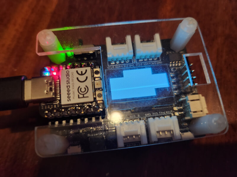
Grove - Expansion Board - I2C Display
To test this setup we can use an existing sample with Zephyr:
cd ~/zephyrproject/zephyr
west build -p always -b xiao_rp2040 samples/drivers/display -- -DSHIELD=seeed_xiao_expansion_board
You'll see a display showing multiple black boxes and a blinking box in the corner given this display only supports two colors.
Let's dive into this example a bit to see why it works:
/ {
    chosen {
      zephyr,display = &ssd1306;
    };
};

&xiao_i2c {
  status = "okay";

  ssd1306: ssd1306@3c {
    compatible = "solomon,ssd1306fb";
    reg = <0x3c>;
    width = <128>;
    height = <64>;
    segment-offset = <0>;
    page-offset = <0>;
    display-offset = <0>;
    multiplex-ratio = <63>;
    segment-remap;
    com-invdir;
    prechargep = <0x22>;
  };
};
The shield overlay file in this example sets up a SSD1306 OLED screen at the 0x3C register. It is selected as the zephyr display in the chosen section.
Grove - Expansion Board - Button
To test this setup we can use an existing sample with Zephyr which we will use along with the USB console overlay and conf.
cd ~/zephyrproject/zephyr
west build -p always -b xiao_rp2040 samples/basic/button -- -DDTC_OVERLAY_FILE="$(dirname $(pwd))/applications/xiao-zephyr-examples/console.overlay" -DEXTRA_CONF_FILE=$(dirname $(pwd))/applications/xiao-zephyr-examples/console.conf -DSHIELD=seeed_xiao_expansion_board
After uploading the uf2 file connect to monitor:
screen /dev/ttyACM0 115200
Pressing the button with the sample will trigger the onboard LED to light up.
You will see results returned from the console:
*** Booting Zephyr OS build v3.6.0-2212-gc38ea288eee9 ***
Set up button at gpio@40014000 pin 27
Set up LED at gpio@40014000 pin 25
Press the button
Button pressed at 1934761489
Button pressed at 2178879257
Button pressed at 3084766465
Button pressed at 3388674993
Let's dive into this example a bit to see why it works:
/ {
    aliases {
      sw0 = &xiao_button0;
    };

    buttons {
      compatible = "gpio-keys";
      xiao_button0: button_0 {
        gpios = <&xiao_d 1 (GPIO_PULL_UP | GPIO_ACTIVE_LOW)>;
        label = "SW0";
        zephyr,code = <INPUT_KEY_0>;
      };
    };
};
The app overlay file is used to setup various board components. Using this file the button example can be utilized as the overlay allows the Zephyr to configure the button and make it available for the associated code.
In this case GPIO 27 corresponds with Pin A1/D1 on the Xiao RP2040. It is setup in this overlay to act as a button and is aliased to the sw0 name to allow it to be used for the sample which has code expecting this.
Grove - Expansion Board - Buzzer
We'll activate our buzzer using the blinky PWM example to control its activation via a PWM signal. For this we'll use a custom overlay which enables the PWM for the A3 pin.
cd ~/zephyrproject/zephyr
west build -p always -b xiao_rp2040 samples/basic/blinky_pwm -- -DDTC_OVERLAY_FILE="$(dirname $(pwd))/applications/xiao-zephyr-examples/xiao-rp2040/xiao_expansion_buzzer.overlay"
After uploading the uf2 file you should begin hearing a series of buzzes which change in sound as the sample runs its course.
Let's look at why this works:
/delete-node/ &pwm_led0;

/ {
    aliases {
        pwm-led = &pwm_led0;
    };
};

&{/pwm_leds} {
    status = "okay";
    compatible = "pwm-leds";

    pwm_led0: pwm_led0 {
        status = "okay";
        pwms = <&pwm 13 PWM_HZ(880) PWM_POLARITY_NORMAL>;
    };
};

&pinctrl {
    pwm_ch6b_default: pwm_ch6b_default {
        group1 {
            pinmux = <PWM_6B_P29>;
        };
    };
};

&pwm {
    status = "okay";
    pinctrl-0 = <&pwm_ch6b_default>;
    divider-frac-6 = <15>;
    divider-int-6 = <255>;
};
The overlay in use first removes the existing pwm_led0 node as this board is supported via an onboard LED setup for PWM. It then configures the A3 pin for use as a PWM.
We're using channel 6B here for the PWM as the associated pin for A3 on the Xiao RP2040 is pin 29. See the RP2040 pinctrl documentation for more information / the pin mapping of other pins.
Grove - Expansion Board - SD Card
We'll use the filesystem sample here along with the Xiao Expansion Board shield to try interfacing with the SD card reader over SPI. The expansion board shield has the CS pin configured for the associated &xiao_d 2 pin so no work is needed on your part for associating this capability with the board aside from adding the shield. To further prepare it we are using a custom config that enables the SD card functionality.
cd ~/zephyrproject/zephyr
west build -p always -b xiao_rp2040 samples/subsys/fs/fs_sample -- -DDTC_OVERLAY_FILE="$(dirname $(pwd))/applications/xiao-zephyr-examples/console.overlay" -DEXTRA_CONF_FILE="$(dirname $(pwd))/applications/xiao-zephyr-examples/console.conf $(dirname $(pwd))/applications/xiao-zephyr-examples/xiao_expansion_sd.conf" -DSHIELD=seeed_xiao_expansion_board
After uploading the uf2 file connect to monitor:
screen /dev/ttyACM0 115200
*** Booting Zephyr OS build v3.6.0-2566-gc9b45bf4672a ***
[00:00:00.201,000] <inf> sd: Maximum SD clock is under 25MHz, using clock of 24000000Hz
[00:00:00.202,000] <inf> main: Block count 15519744
Sector size 512
Memory Size(MB) 7578
Disk mounted.

Listing dir /SD: ...
[FILE] IMAGE1.JPG (size = 58422)
[FILE] IMAGE2.JPG (size = 97963)
In this case my SD card had two files. Their names and their sizes were outputted to my console.
Let's look over the relevant elements at play here:
CONFIG_SPI=y
CONFIG_DISK_DRIVER_SDMMC=y
CONFIG_GPIO=y
In the associated config we're enabling SPI, the SDMMC disk driver, and the GPIO. Without this config the overlay will lead to an error as the sample is unable to find the SD card.
The relevant part of the Xiao Expansion Board shield is shown below:
&xiao_spi {
    status = "okay";
    cs-gpios = <&xiao_d 2 GPIO_ACTIVE_LOW>;

    sdhc0: sdhc@0 {
        compatible = "zephyr,sdhc-spi-slot";
        reg = <0>;
        status = "okay";
        mmc {
            compatible = "zephyr,sdmmc-disk";
            status = "okay";
        };
        spi-max-frequency = <24000000>;
    };
};
As mentioned previously the &xiao_d 2 pin mapping is used to allow the D2 pin to be selected for this regardless of the board used so long as it supports the &xiao_d pin setup.
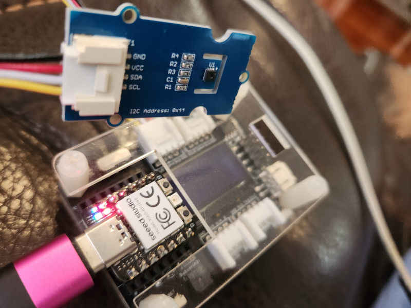
Grove - Temperature and Humidity Sensor (SHT31)
First solder on pins and connect your Xiao RP2040 to the expansion board. Then connect a grove connector cable between the Grove SHT31 and one of the I2C ports on the expansion board.
To test this setup we can use an existing sample with Zephyr which we will enable USB console support with our overlay and conf.
cd ~/zephyrproject/zephyr
west build -p always -b xiao_rp2040 samples/sensor/sht3xd -- -DDTC_OVERLAY_FILE="$(dirname $(pwd))/applications/xiao-zephyr-examples/sht31.overlay $(dirname $(pwd))/applications/xiao-zephyr-examples/console.overlay" -DEXTRA_CONF_FILE=$(dirname $(pwd))/applications/xiao-zephyr-examples/console.conf
After uploading the uf2 file connect to monitor:
screen /dev/ttyACM0 115200
You will see results returned from the console:
*** Booting Zephyr OS build v3.6.0-2212-gc38ea288eee9 ***
SHT3XD: 26.20 Cel ; 52.49 %RH
SHT3XD: 26.19 Cel ; 52.69 %RH
SHT3XD: 26.20 Cel ; 52.75 %RH
SHT3XD: 26.24 Cel ; 52.88 %RH
SHT3XD: 26.24 Cel ; 52.67 %RH
SHT3XD: 26.23 Cel ; 52.49 %RH
SHT3XD: 26.23 Cel ; 52.48 %RH
SHT3XD: 26.24 Cel ; 52.30 %RH
Let's dive into this example a bit to see why it works:
 &xiao_i2c {
    sht3xd@44 {
            compatible = "sensirion,sht3xd";
            reg = <0x44>;
        };
    };
The app overlay file is used to setup various board components. Using this file the SHT31 example can be utilized as the overlay informs the sample logic how to configure the sensor for our board.
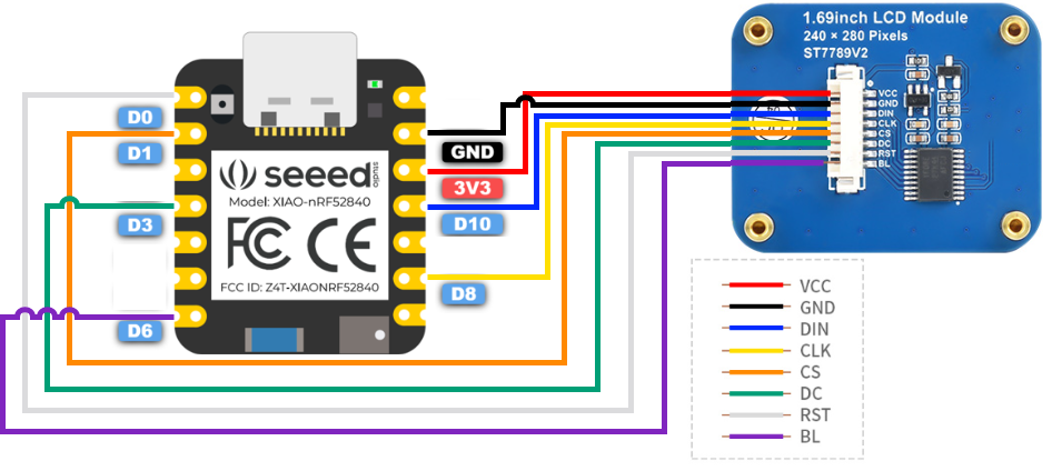
1.69inch LCD Display Module, 240×280 Resolution, SPI Interface
For this example we'll use SPI to connect to a 1.69 inch LCD with a 240x280 resolution.
First connect your board to the LCD screen using the following image as a guide (in this case we're using the Xiao RP2040 but the same pin layout is used for connecting here).
| 1.69-inch LCD SPI Display | XIAO RP2040 |
|---|---|
| VCC | 3V3 |
| GND | GND |
| DIN | D10 |
| CLK | D8 |
| CS | D1 |
| DC | D3 |
| RST | D0 |
| BL | D6 |
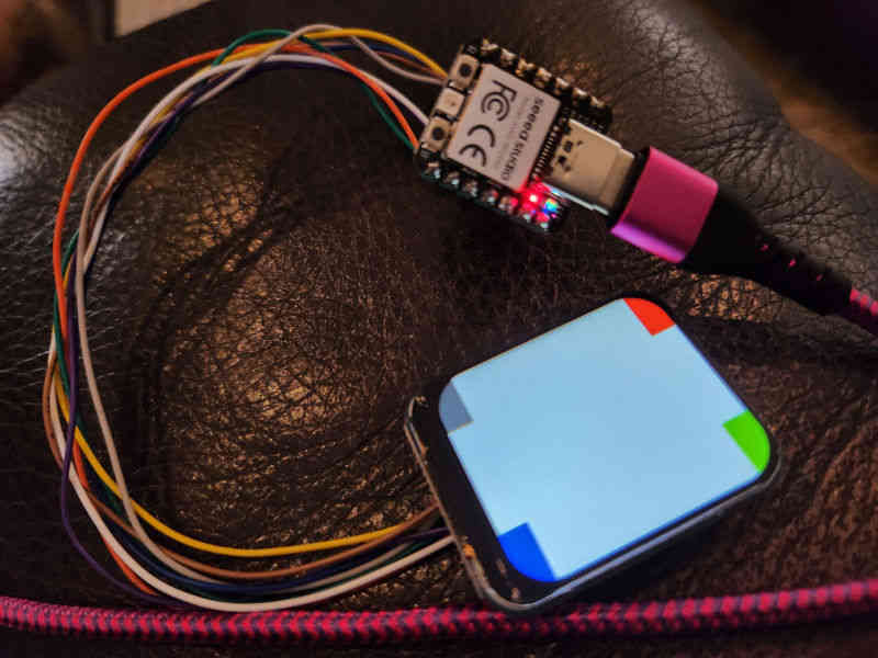
Next with the hardware prepared we can build the uf2 file for flashing:
cd ~/zephyrproject/zephyr
west build -p always -b xiao_rp2040 samples/drivers/display -- -DDTC_OVERLAY_FILE=$(dirname $(pwd))/applications/xiao-zephyr-examples/240x280_st7789v2.overlay -DEXTRA_CONF_FILE=$(dirname $(pwd))/applications/xiao-zephyr-examples/240x280_st7789v2.conf
When this completes, move the build file from build/zephyr/zephyr.uf2 to the mounted Xiao RP2040 (remember you can hold the boot button down while plugging in to enter this state) which will reset the device with the new firmware.
With the new firmware in place the device now shows the same demo screen we saw previously on the expansion board just now updated for the color LCD over SPI.
✨ Contributor Project
- This project is supported by the Seeed Studio Contributor Project.
- Thanks Tim's efforts and your work will be exhibited.
Tech Support & Product Discussion
Thank you for choosing our products! We are here to provide you with different support to ensure that your experience with our products is as smooth as possible. We offer several communication channels to cater to different preferences and needs.