Creating XIAO Components on Flux.ai
Flux is a browser-based PCB design tool that enables seamless collaboration between electronics teams. The tool's intuitive interface allows users to create schematics and layouts quickly and easily, while its built-in simulation capabilities help to ensure that designs are accurate and error-free.
In this section we are going to cover Creating Seeed Studio XIAO series Components on Flux.ai.
Browser Seeed Studio XIAO Series PCB design
Seeed Studio XIAO SAMD21
Seeed Studio XIAO RP2040
Seeed Studio XIAO nRF52840
Seeed Studio XIAO nRF52840 Sense
Seeed Studio XIAO ESP32C3
Seeed Studio XIAO ESP32S3
Seeed Studio XIAO ESP32S3 Sense
Knowledge about Flux.ai - Creating parts
Parts in Flux are made of 5 main components. All these components are optional, but a part missing a component won't offer its full capabilities:
| Concept | Description |
|---|---|
| Schematic | The "inside" view of a part, represented by terminals only. |
| Symbol | The representation of a part when it is dragged into another project, usually familiar to users from other tools. |
| Footprint | Represents how the physical part will sit on the board. |
| 3D model | Shows the 3D shape and dimensions of the part. |
| Simulation model | Describes how the part should behave during simulation. |
Getting Started
Step 1 - Creating a new part schematic
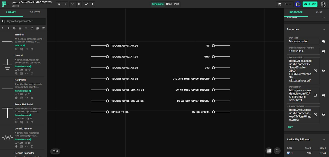
The very first step is to create a new blank project, you can do so in the main Flux menu in the top-right corner. Terminals are the basis of every part that is created in Flux. They allow the part to interact with the rest of the circuit. To add terminals to a new part, go to the library, search "Terminal" and drag in as many as you need.
In this example we are going to add Seeed Studio XIAO ESP32S3 so i just added 14 terminal pins and given the names and numbers
You can give more information’s about your parts in part properties like manufacturer part number (MPN)manufacturer name , data sheet URL ....etc. entering MPN of the component will help you find current stock availability and price of the components.
Step 2 - Creating a symbol
Flux works slightly differently than other tools you might be used to. In Flux, parts have two different views, the schematic, and the symbol. The schematic view from step 1 only contains the terminals. Symbols are only visible when a part is placed into a project. Now let's create a symbol for our xiao but for the we need to use some external tool like illustrator or Inkscape. the designed symbol format needs to be in .svg
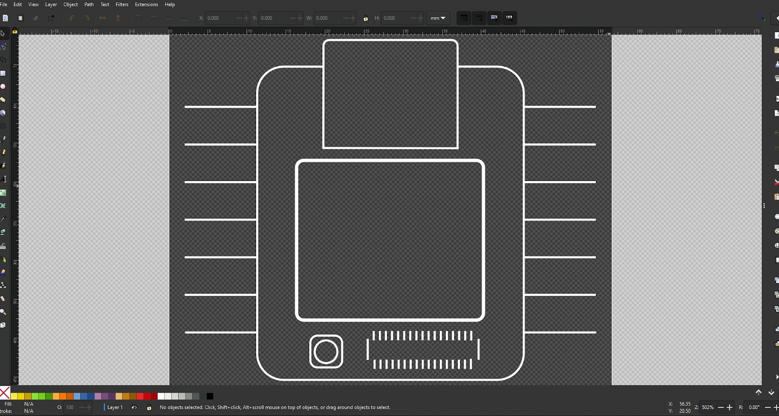
Things need to consider designing the symbol ,
- every shape and line should be white, with 1px stroke width and no fill.,
- Pins are typically 10 to 18 pixels long. Now export the symbol as an SVG file.
Step 3 - Add the SVG as an asset
Once you have the SVG file, add it as an asset. To add an external file as an asset. Make sure no object has been selected (click on the empty canvas).On the right drawer, scroll down until you find the assets panel. Open it and click on "Add" (or "Manage"). This will open the assets dialogue. Then click on "Add item" and select the file from your local drive. Match the pin position with the custom symbol. By default, all terminals will be located at the centre of the symbol. To position the terminals to the desired location, there are a few more step.
- Publish the part to the library.
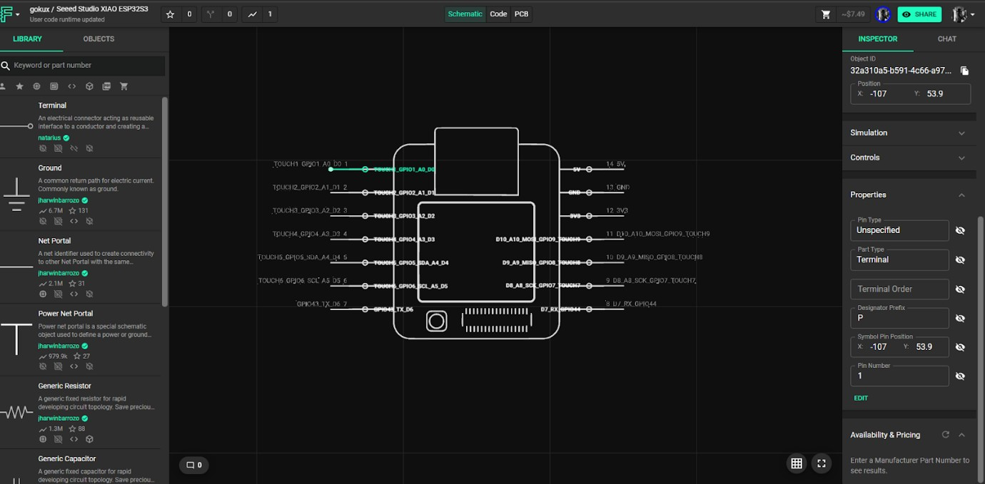
- Create a New blank project and drag the part you're importing.
- You'll notice that both terminals are at the centre of the symbol. Now go back to the imported part.
- You'll need to do this process for every terminal in your part. a) Select the terminal and find the "Properties" menu in the right-side panel. b) In the "Symbol Pin Position" field, type the desired x and y coordinates for the terminal to sit on the symbol. c) Publish the part and go back to the new project. You'll see a "Update available for your parts" legend in the bottom left. Click on "Review" and accept the changes. d) You'll notice that the terminals have moved. You might need to repeat this process a few times to nail the perfect position.
Step 4 - Creating a footprint
Footprints are very simple to create in Flux. They consist of pads, lines, shapes, and text nodes that can be added directly in the Flux PC editor.
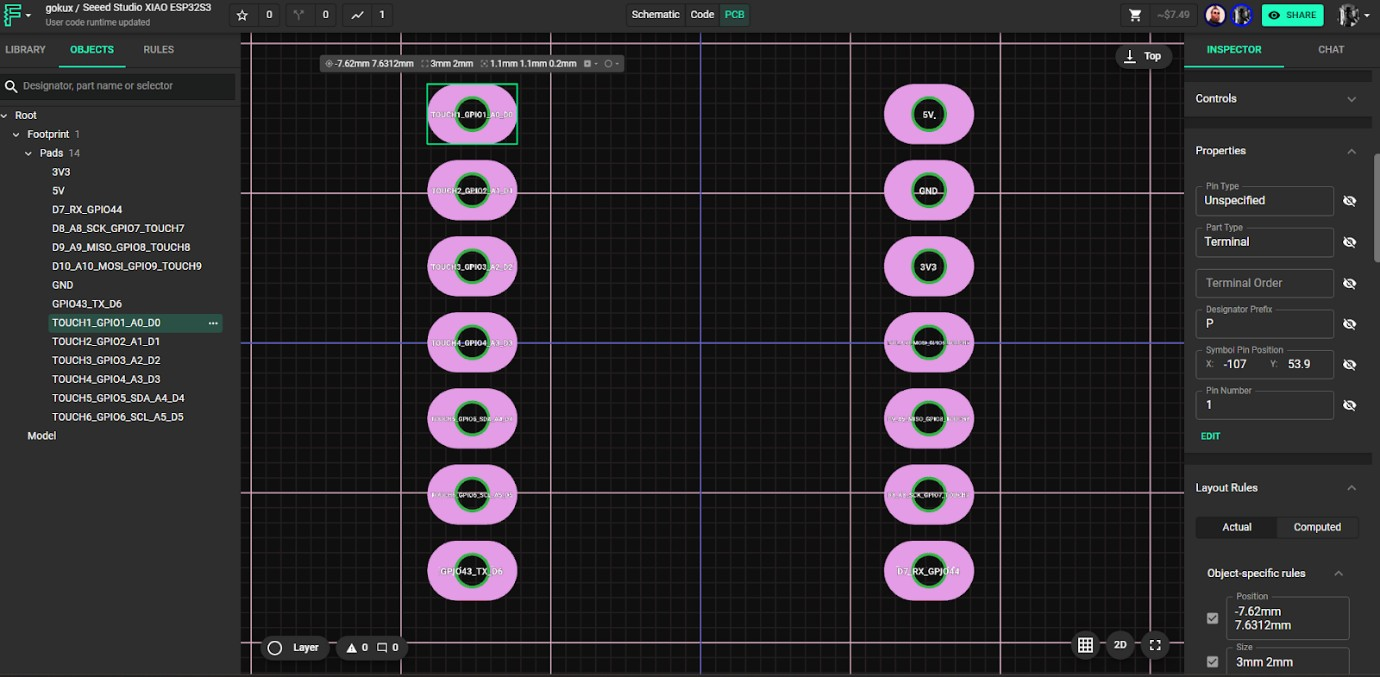
When you first create a footprint on flux ,all of the pads will be in one place, which will appear as small dots. For changing the pad position Select the pad to move on the right panel on object specific rules find position rule , Enter the desired x and y positions in millimetres.
Step 5 - Modifying pad size and shape
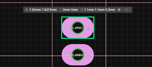
By clicking the one of the pads you can change its shape , position , hole diameter and other properties .for xiao i gone with 3mm*2mm size pad and 1.1mm hole. Placed each pin 2.54mm apart by utilizing the x and y position millimetres. Adding 3d model
Now we need to add a 3d model of xiao, flux support .step file for 3d models , you can download it from official wiki page.
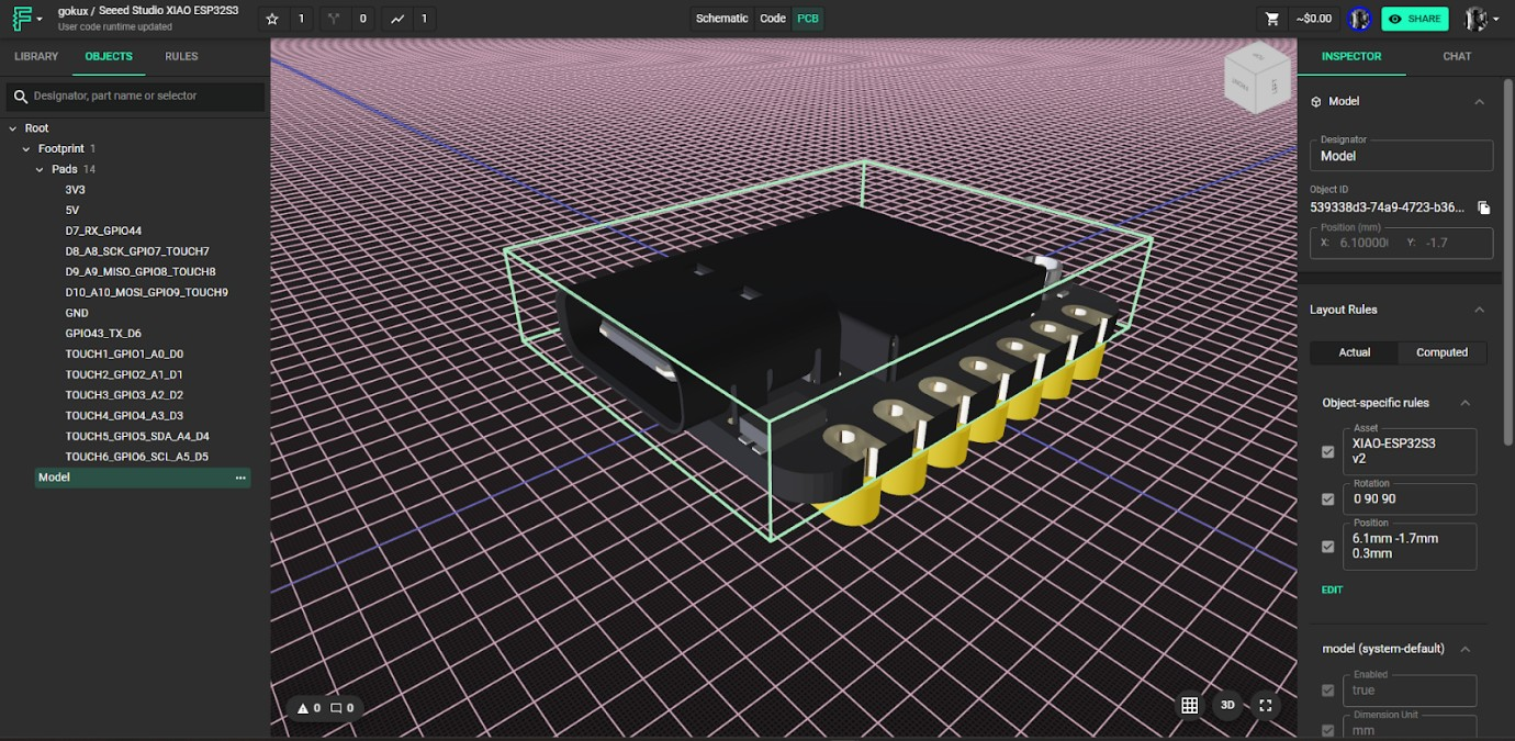
You can upload the 3d model form the assist section. more detailed about adding the 3d model is available in the video. You can change the x y z position and rotation form the object specified rule. Using this you can position the 3d model in top of the soldering pads. Publishing to the library After creating a component, it is time to publish it
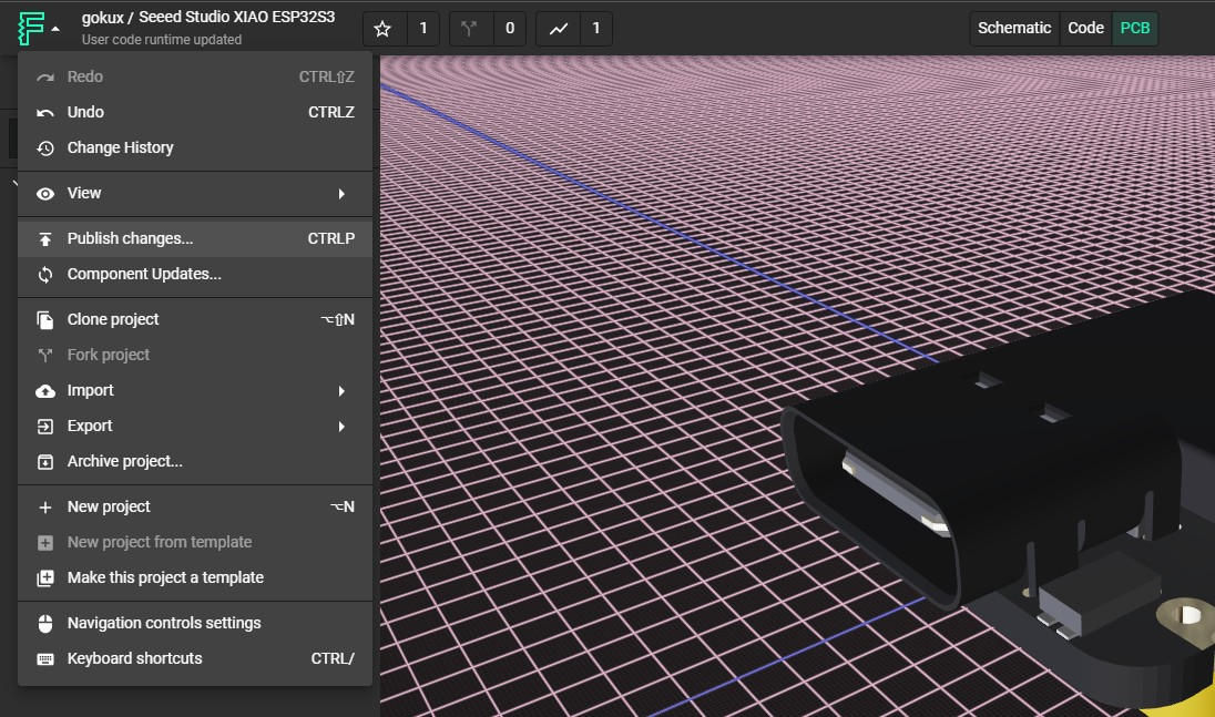
Select the flux logo in the top left corner then select publish changes. Now our components well be available in our profile , also it will show up in the public library search
What's More - Video of Tutorial
✨ Contributor Project
- This project is supported by the Seeed Studio Contributor Project.
- Thanks Gokul's efforts and your work will be exhibited.
Tech Support & Product Discussion
Thank you for choosing our products! We are here to provide you with different support to ensure that your experience with our products is as smooth as possible. We offer several communication channels to cater to different preferences and needs.