Getting S2100 started with Analog Input Sensor
Let's get started on learning how to use the S2100 with an analog input sensor. Once we've got that down, we'll move on to the basics of S2100's application. This will give you a good idea of how to connect your own customized sensor in the future.
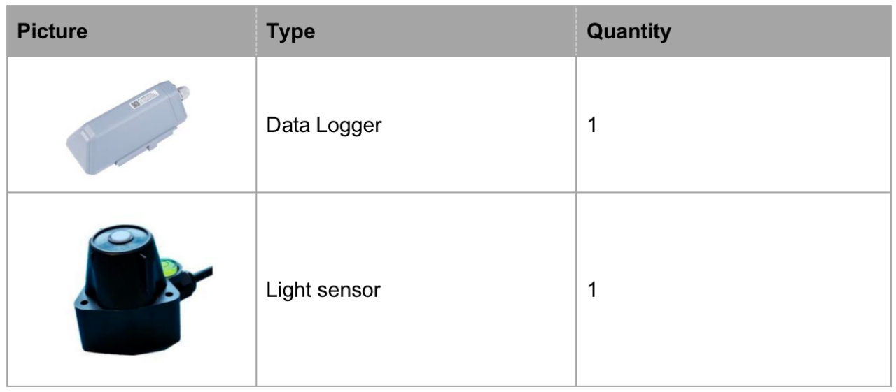
Get these items ready
- Data logger
- Light sensor(as an example)
- Cross screwdriver(Cross recess No.2)
- SenseCAP Mate APP
Connect the Sensor Probe
First, we need to do the wiring. Please follow the below steps.
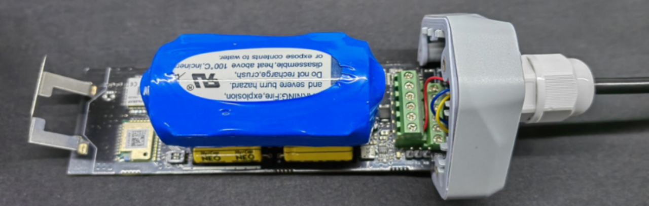
Disassemble the Data Logger
- Unscrew three screws.
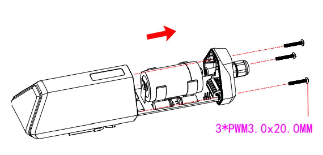
- Take down the cover.
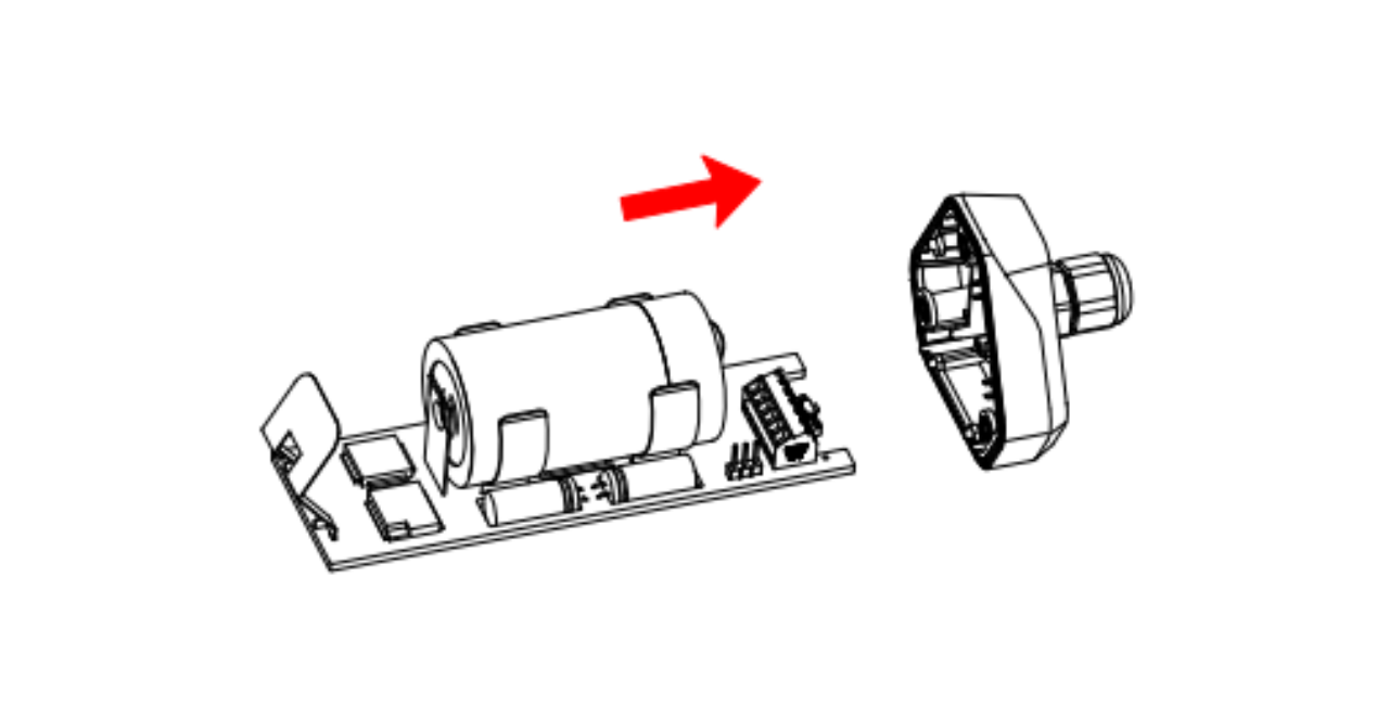
- Remove the threaded cap and pass it through the cable of the sensor, pass it through the bottom cover, and connect it to the wiring terminal.
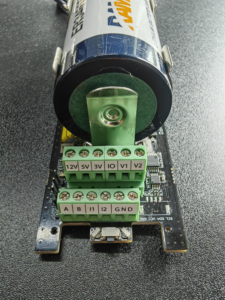
Wiring terminal description
| No. | Pin | Description |
|---|---|---|
| 1 | 12V | External 12V input voltage. The Data Logger can be powered by an external 12V DC power supply. When using 12V power supply, the battery will serve as backup power supply. |
| 2 | 5V | 5V output voltage, providing 5V voltage to the sensor. |
| 3 | 3V | 3V output voltage, providing 3V voltage to the sensor. |
| 4 | IO | Acquisition level or pulse input |
| 5 | V1 | The voltage input of 0 to 10V is collected |
| 6 | V2 | The voltage input of 0 to 10V is collected |
| 7 | A | RS485 A/+ |
| 8 | B | RS485 B/- |
| 9 | I1 | Collect the current input from 4 to 20mA |
| 10 | I2 | Collect the current input from 4 to 20mA |
| 11 | GND | Ground pin |
| 12 | GND | Ground pin |
Resolution
| Interface | Value |
|---|---|
| Current Input | 4 to 20 mA (2 channel) |
| Current Input Resolution (I1/I2) | 0.001 mA |
| Voltage Input | 0 to 10V (2 channel) |
| Voltage Input Resolution (V1/V2) | 0.01 mV |
Power supply options of sensor
Data Logger supports two power supply modes, we choose the Built-in Battery mode since light sensor only needs a 5v supply:
| Mode | Description |
|---|---|
| Built-in Battery | The Data Logger and sensors are powered by batteries. In this case, the Data Logger can be connected to a 5V sensor. |
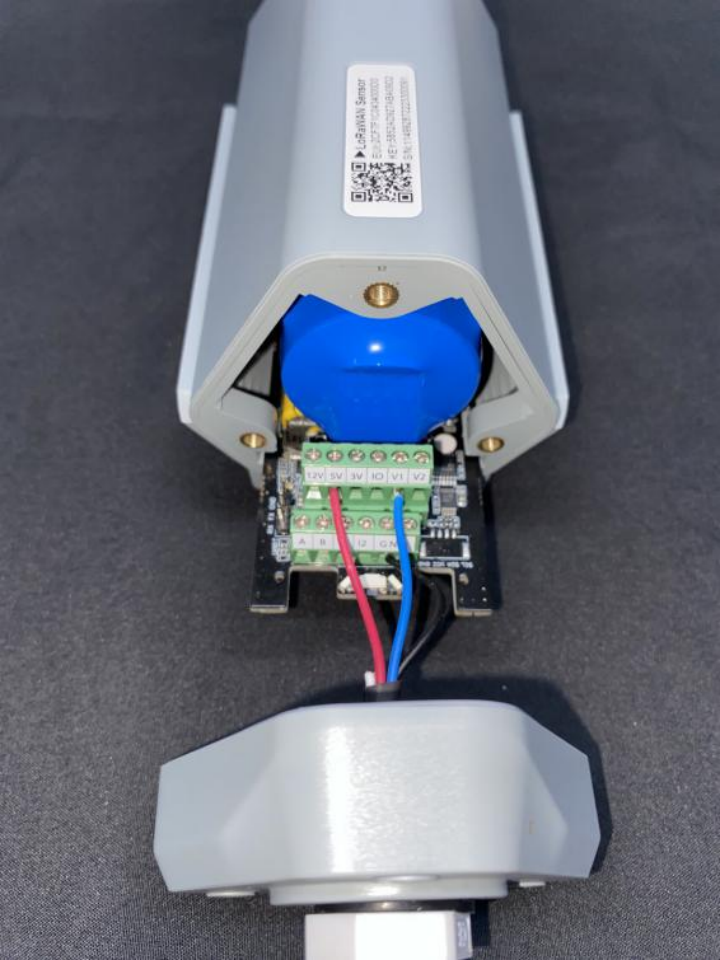
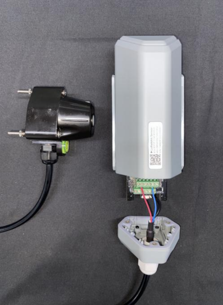
Connect to the Datalogger
Wire sequence of Datalogger:
| Wire Type | Description |
|---|---|
| Red Wire | 5V |
| Black Wire | GND(Any port would be OK.) |
| Yellow Wire | IO |
- Pass the 8-pin wire through the bottom cover and connect it to the base of the Data Logger according to the wire sequence requirements;
- Connect the upper cover, rubber ring and screw cap in sequence
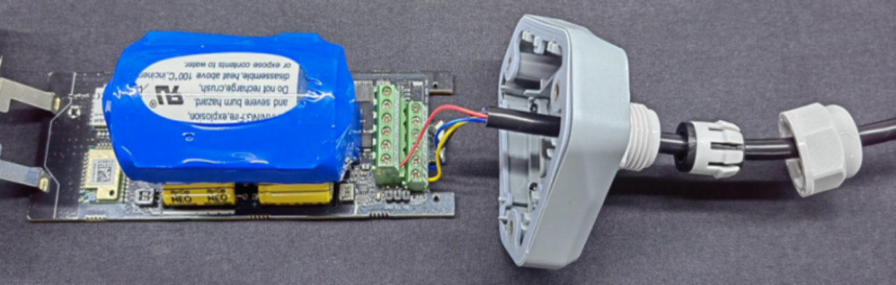
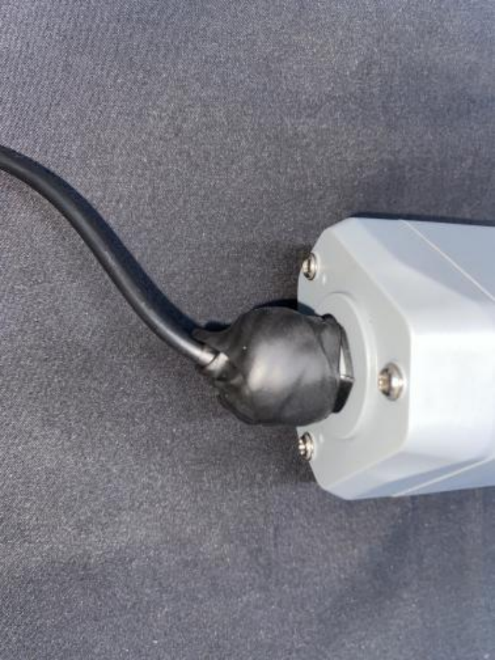
- Tighten the screws and screw caps****to check the waterproofing. If the wire diameter is too thin, add waterproof tape for winding.
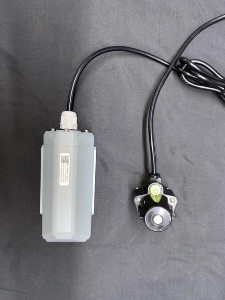
*Note: When assembling the device, it is necessary to install the waterproof pad of the Data Logger and the adapter box, and tighten the screw cap and screw, otherwise the waterproof effect of the device may be affected!
If the wire diameter is too small, it can be wrapped with waterproof tape, as shown below:
We've finished the wiring at this point. Now, let's set up the S2100 and configure it on our APP.
Setup the S2100
Connect to Sensor to App
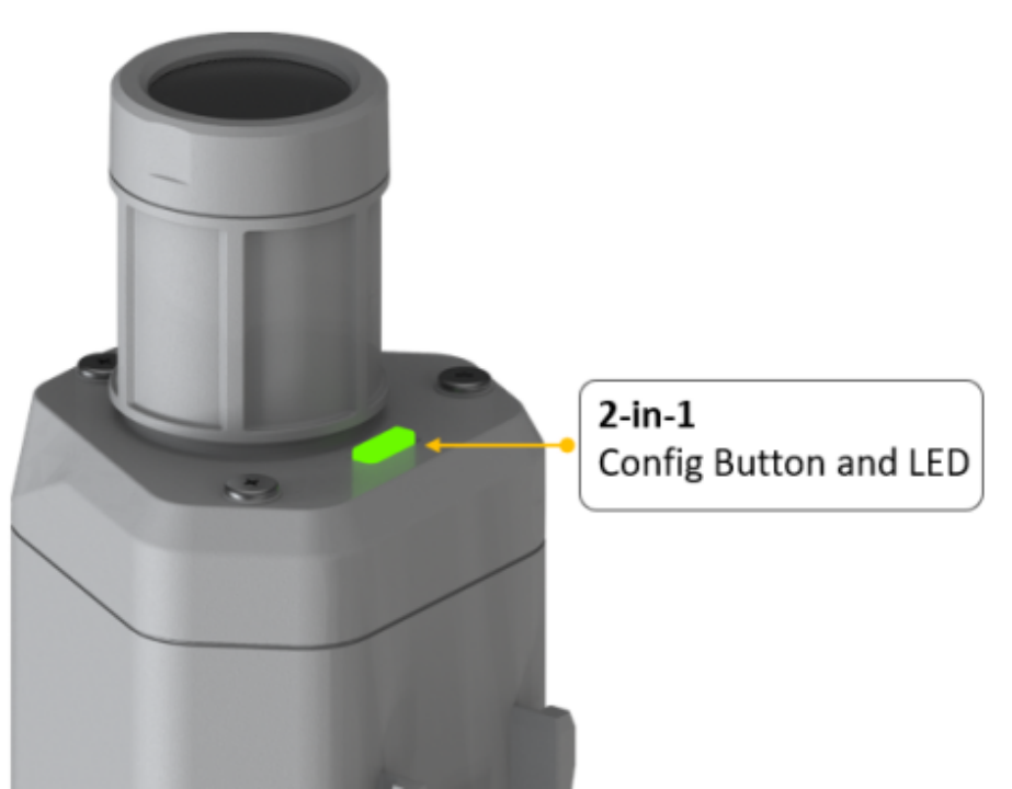
- Press button and hold for 3 seconds , the LED will flash at 1s frequency. Please use the App to connect the sensor within 1 minute; otherwise, the device will power off or reboot.
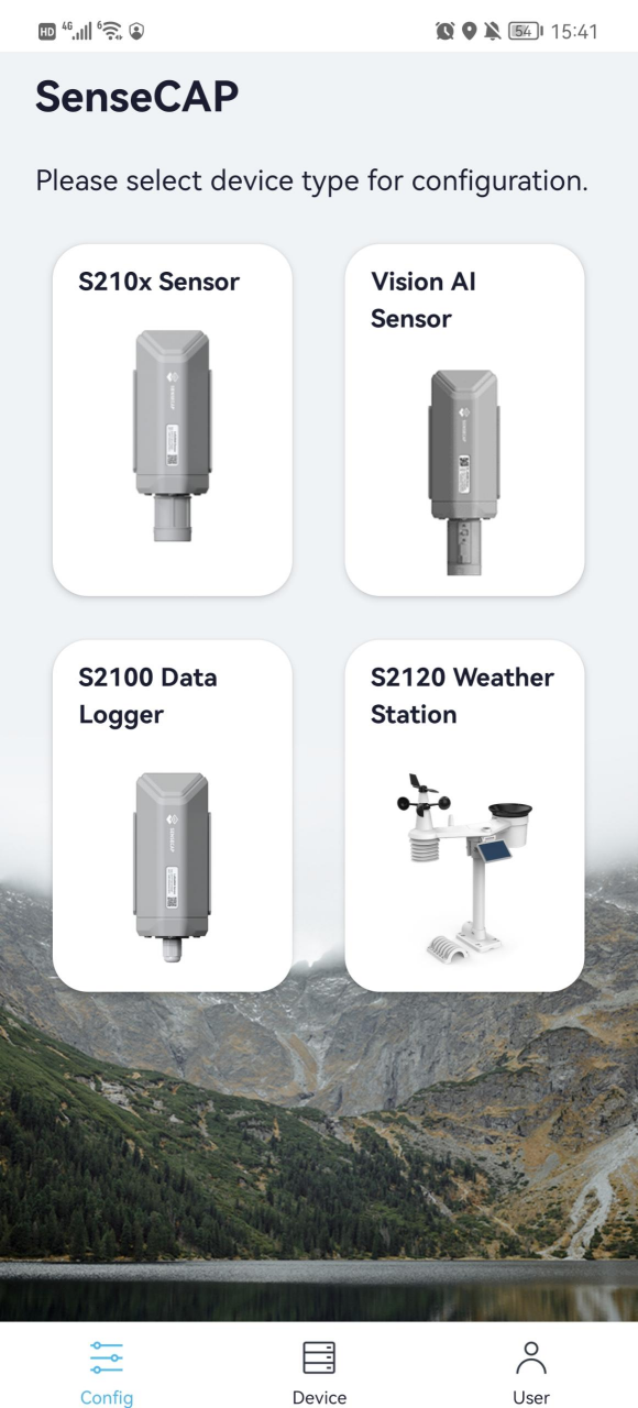
- Please select "S2100 Data Logger".
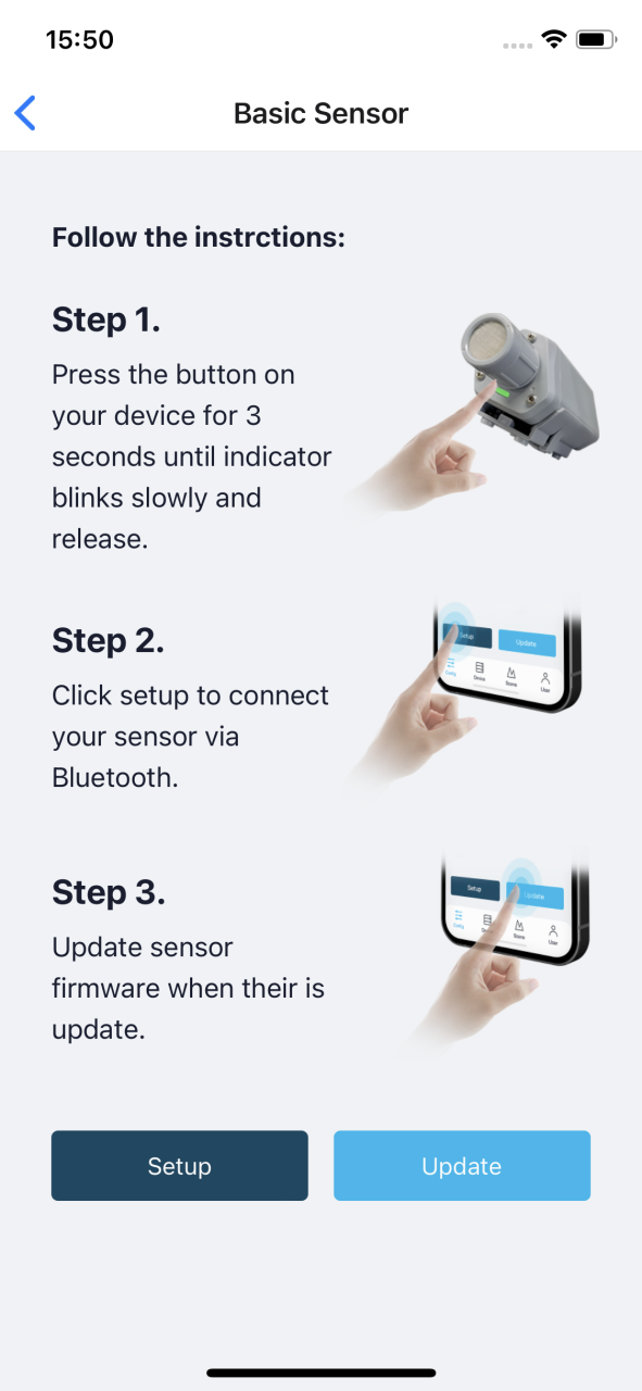
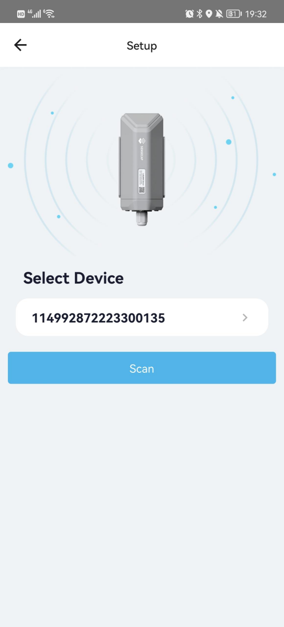
Please click the "Setup" button to turn on Bluetooth and click "Scan" to start scanning the sensor's Bluetooth.
- Select the Sensor by S/N (S/N is on the front label of the sensor). Then, the basic information of the sensor will be displayed after entering.
- Enter configuration mode after Bluetooth connection is successful: LED flashes at 2s frequency.
Configure Basic parameters through App
Select the Platform and Frequency
S210x Sensors are manufactured to support universal frequency plan from 863MHz ~928MHz in one SKU. That is to say, every single device can support 7 frequency plans.
Here we select the "SenseCAP for Helium" or "SenseCAP for TTN". The Frequency Plan based on your actual situation.
*Note: Data Logger can upload data when there is a Helium network around the user. It runs on SenseCAP private Helium Console. Users do not need to create a device on the Helium Console;
SenseCAP for TTN platform needs to be used with SenseCAP LoRaWAN outdoor gateway(https://www.seeedstudio.com/LoRaWAN-Gateway-EU868-p-4305.html)
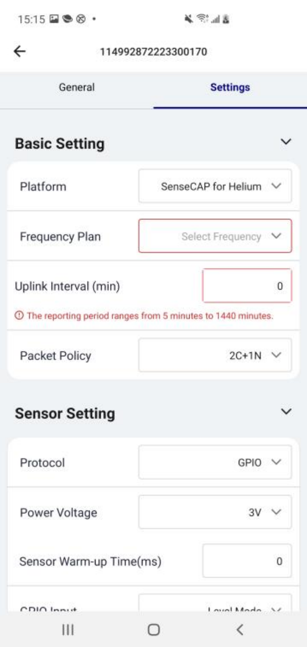
Set the Interval
The working mode of device: wake up the device every interval and collect measurement values and upload them through LoRa.
For example, the device collects and uploads data every 60 minutes by default.

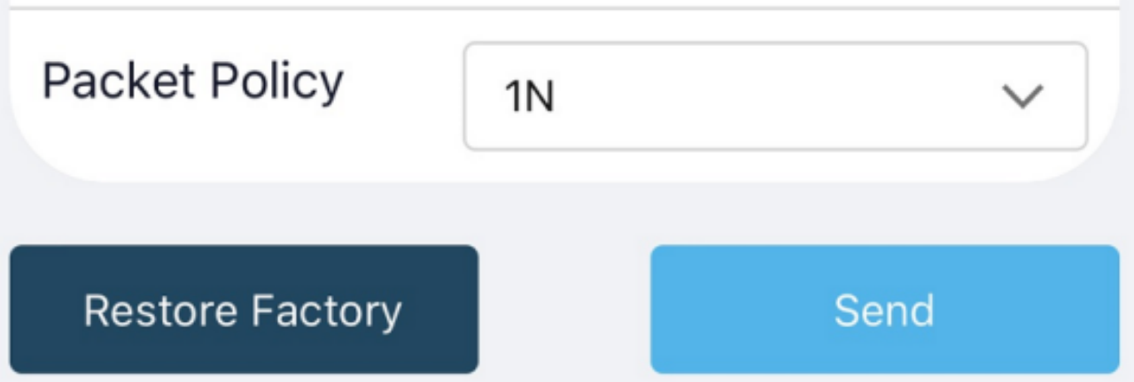
Set the Packet Policy
The sensor uplink packet strategy has three modes, we select 1N here or you can according to your own requirement.
| Parameter | Description |
|---|---|
| 2C+1N (default) | 2C+1N (2 confirm packets and 1 none-confirm) is the best strategy, the mode can minimize the packet loss rate, however the device will consume the most data packet in TTN, or date credits in Helium network. |
| 1C | 1C (1 confirm) the device will sleep after get 1 received confirm packet from server. |
| 1N | 1N (1 none-confirm) the device only send packet and then start to sleep, no matter the server received the data or not. |
Restore Factory Setting
When selecting the SenseCAP platform, you must use the fixed EUI/App EUI/App Key. Therefore, you need to restore the factory Settings before switching back to the SenseCAP platform from other platforms.

When we make a mistake or want to reset everything, we can click the button. The device will be restored to the factory's default configuration.
*Note: The "Restore Factory" function can only reset the Basic Setting.
Configure Analog Sensor via App
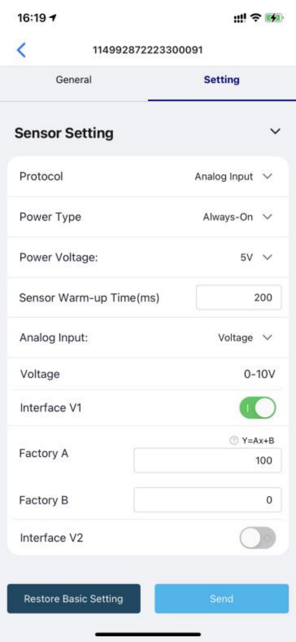
Select the “Protocol” as “Analog Input”. Then set the following parameters in turn.

Select the Power Type as Periodical power.
| Power Voltage | We select 5V here. |
|---|---|
| Sensor Warm-up Time | The warm-up time denotes the amount of time it takes for the sensor to attain its highest accuracy or performance level once the voltage supply has been applied. We enter 200(ms) here. |
| Voltage Range | 0-10V (The Data Logger can collect voltage signals within 0~10V and automatically adjust the upper limit to increase accuracy). We select Voltage here. |
| Interface V1 | The Data Logger supports two analog voltage signals. When the sensor wire is connected to V1/V2, the configuration can be enabled. We enable Interface V1 here. |
| Interface V2 | |
| Y= Ax + B | "Y": It is the value Data Logger will upload. "x": It is the original current value. Factory A: Custom values that can be scaled up or down by multiples of the "x". Factory B: A custom value that increments or diminishes the value of the "x". By setting the values of A and B, you can calculate the desired value. We set A as 100 , B as 0 here. |
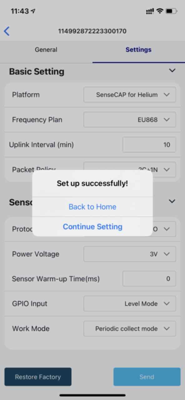
After the configuration information is completed, click "Back to Home" (at this time, the node and the APP Bluetooth will be automatically disconnected), and the Data Logger will try to connect to the network (the LED indicator flashes red slowly when trying to connect to the network, and flashes green quickly after the network is successfully connected);
Check data on the SenseCAP Portal
Bind Sensor to SenseCAP Portal
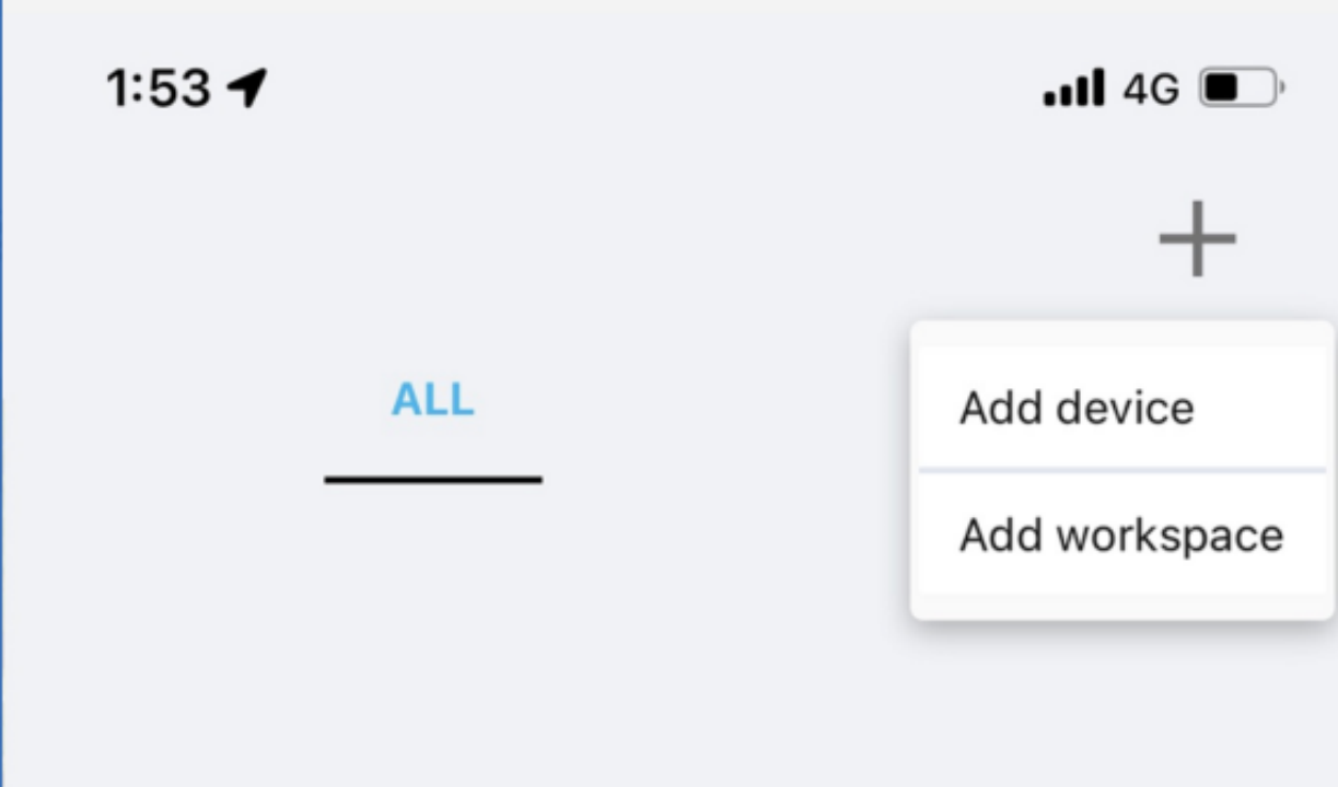
Please open SenseCAP Mate App.
-
Scan QR Code
-
Click "Add device" on the upper-right corner of device page to enter the device binding page.
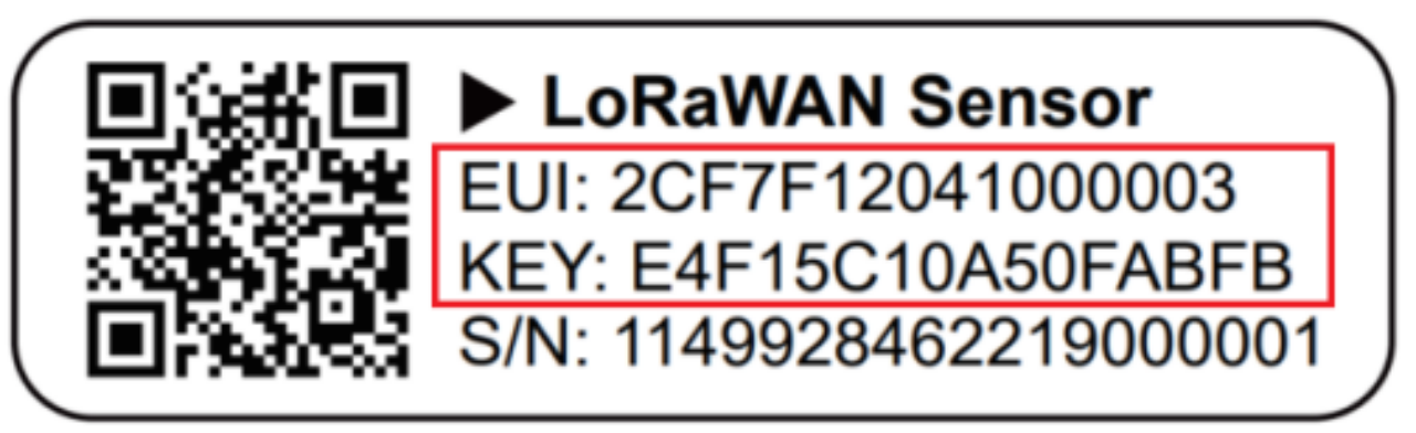
- Scan the QR code on the device to bind the device to your account. If you do not set it to a designated group, the device will be put into the "default" group.
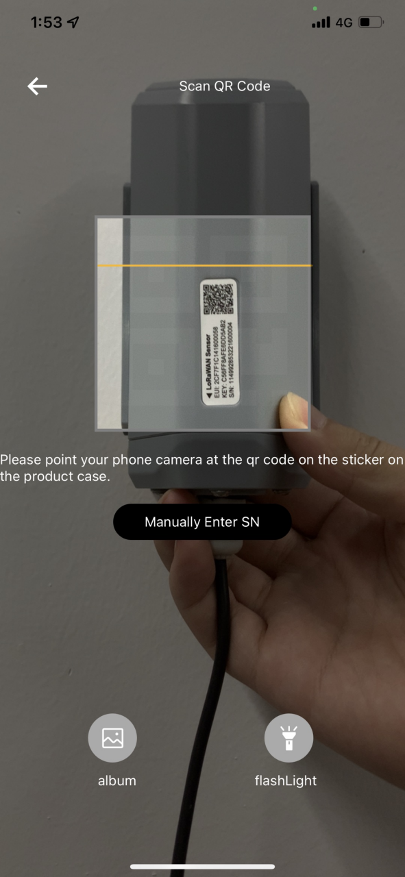
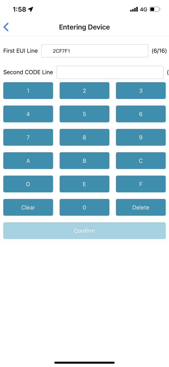
- Manually fill in the EUI
If the QR code sticker is damaged, you can manually fill in the EUI of the device to bind the device to your account. Please make sure you put in the EUI in the format suggested by the system and then click "confirm".
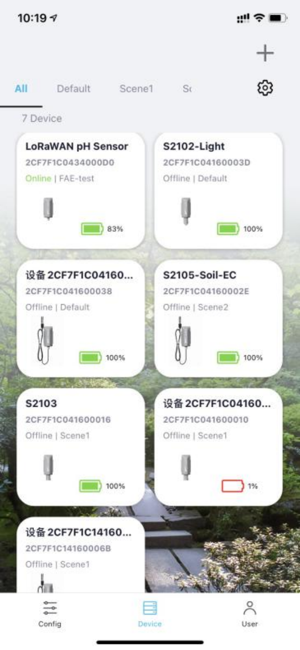
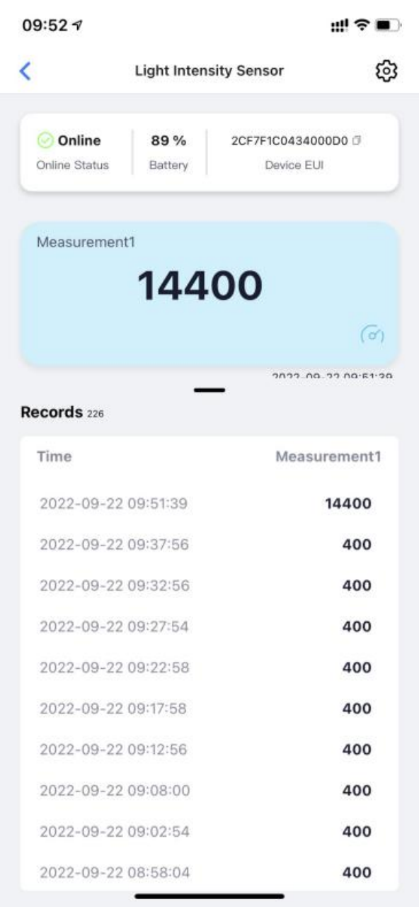
Check Data on SenseCAP Mate APP
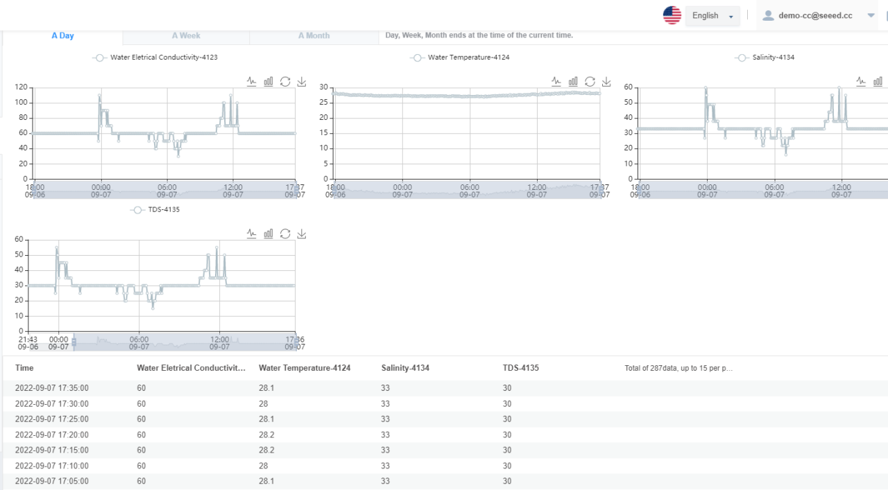
Finally, On the SenseCAP App or the website http://sensecap.seeed.cc/ , you can check the device online status and the latest data. In the list for each Sensor, you can check its online status and the time of its last data upload.
Also, you can check the date on SenseCAP Mate APP.