Expansion Board Base for XIAO
Overview

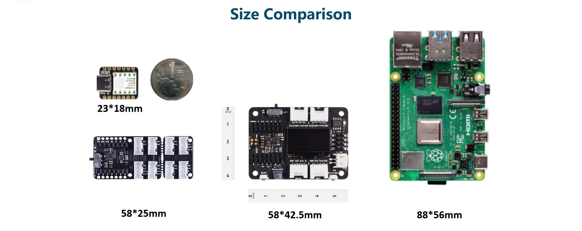
A powerful functional expansion board for Seeed Studio XIAO of only half Raspberry Pi 4 size. It enables build prototype and project in easy and quick way. With its rich peripherals including OLED, RTC, expandable memory, passive buzzer, RESET/User button, 5V servo connector, multiple data interfaces… you could explore infinite possibilities of Seeed Studio XIAO . Circuitpython is also well supported by this board.
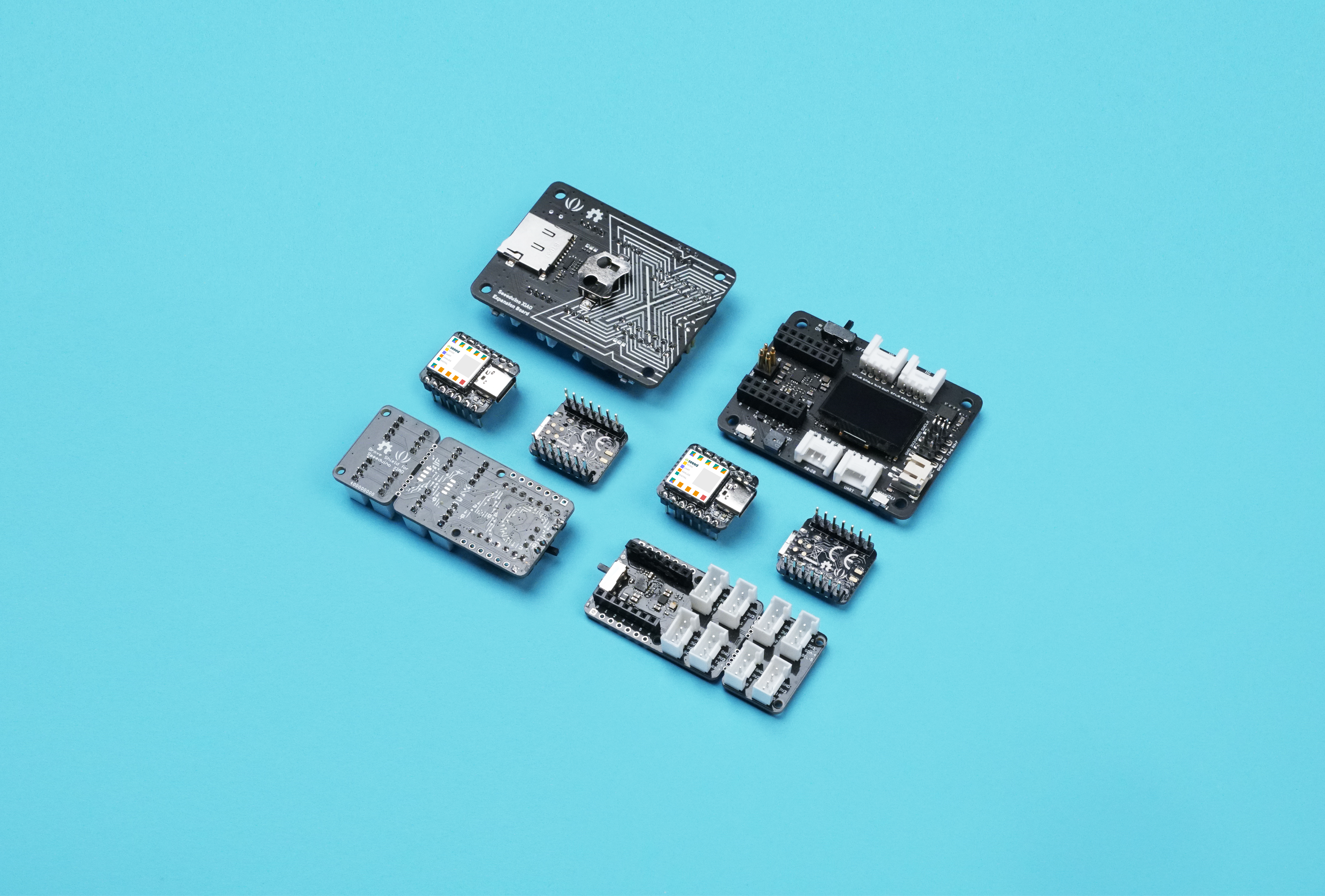
As Seeed Studio XIAO form factor, all Seeed Studio XIAO boards support both Grove Shield for Seeed Studio XIAO and Seeed Studio Expansion Base for XIAO. There is a slight difference between the pins and refer to the Pinout it is easy to manage.
Seeed Studio XIAO SAMD21 , Seeed Studio XIAO RP2040, and Seeed Studio XIAO nRF52840 are compatible to the Seeed Studio Expansion Base for XIAO.
Features
- Quick Prototyping: Easy debug and Reset with RESET button and SWD pin led out to male header.
- Rich peripherals: OLED display, RTC, expandable memory space, passive buzzer, user button, on board battery management chip.
- No Soldering Needed: All pin led out. Convenient plug and play Grove connectors support multiple data protocols, including IIC, UART, Analog/Digital.
- Circuit Python Supported: Well supports circuit python. MicroSD card slot enables memory space expand, making it possible to allocate more libraries needed in prototyping and project building.
- Mini Size: Compact and elegant with only half Raspberry Pi 4 size, especially suitable for projects require mini size.
Specification
| Item | Value |
|---|---|
| Operating voltage | 5V / 3.7V Lithium Battery |
| Charging current | 460mA (Max) |
| RTC timer precision | ± 1.5S/DAY(25°C) |
| RTC battery | CR1220 |
| Display | 0.96" OLED display |
| Expandable memory | MicroSD card |
| Grove Interface | Grove IIC2, Grove UART1, A0/D0 Grove*1 |
| Other External Equipment | Passive buzzer, user button, 5V servo connector |
Applications
- SWD debug
- Rapid prototyping
- Data display
- Mini Size Project
Part List
| Item | Value |
|---|---|
| Seeed Studio Expansion Base for XIAO | *1 |
This product does not include Seeed Studio XIAO and battery. Because the SWD pins are different, this expansion board does not support the XIAO nRF54L15 and XIAO MG24.Seeed Studio XIAO is constantly introducing new products. To keep up with the latest product developments in this series, visit the XIAO series homepage.
Getting Started
Materials Required
| Seeed Studio XIAO SAMD21 (Pre-solder) | Seeed Studio Expansion Base for XIAO |
|---|---|
|
|
| Get ONE Now | Get ONE Now |

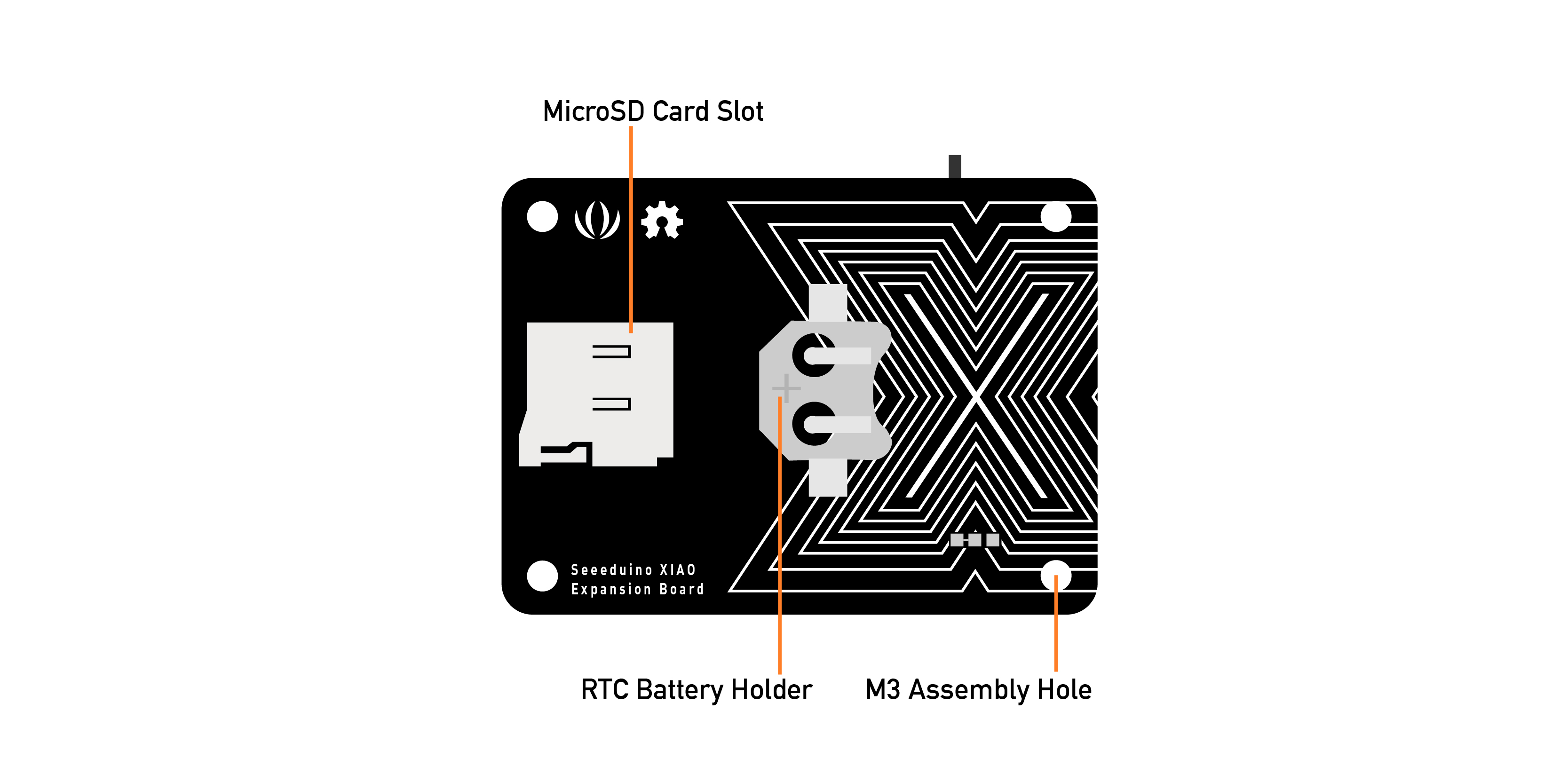
Hardware Overview
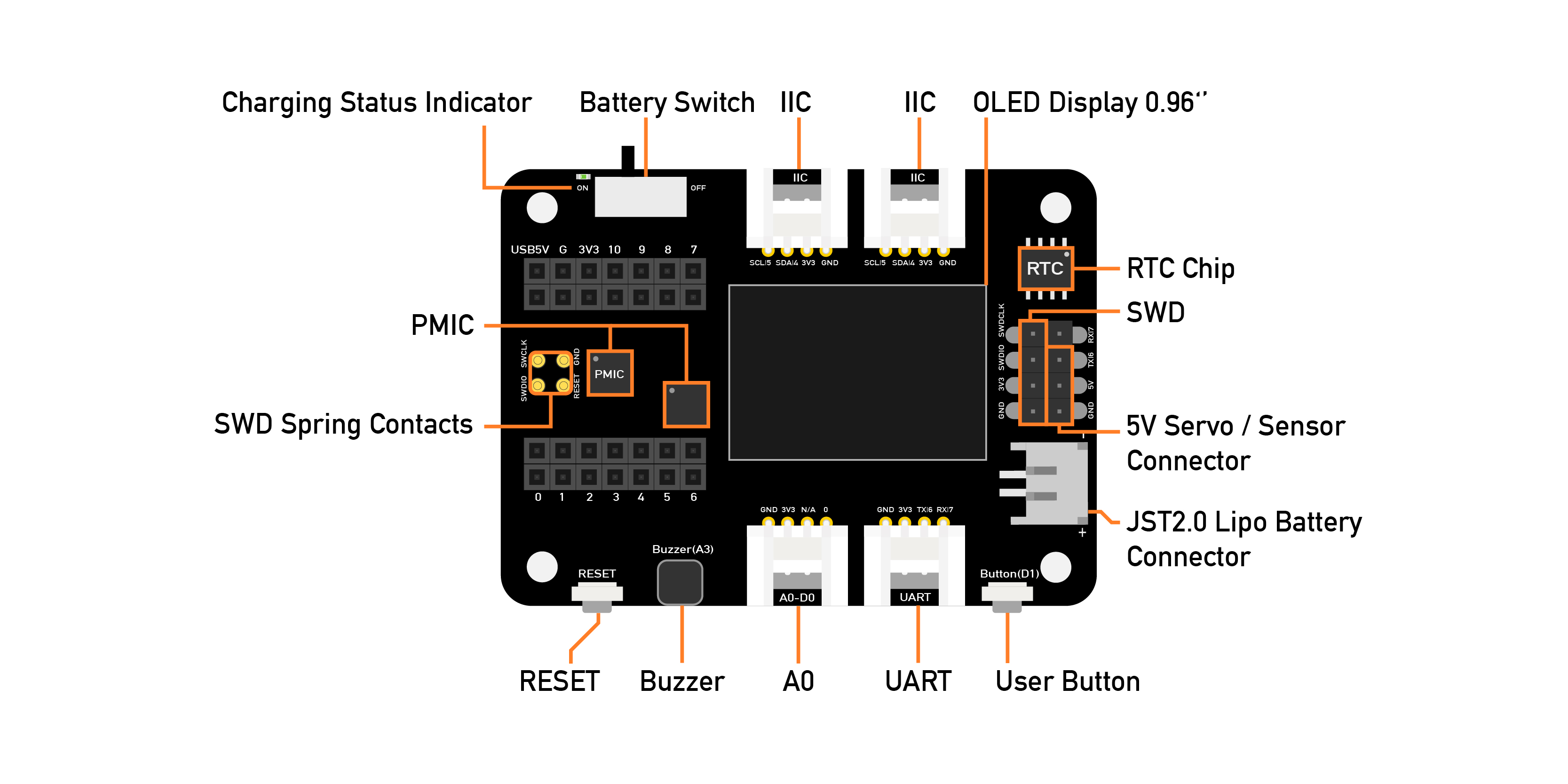
There are an external MicroSD card slot and RTC Battery Holder, the MicroSD card mostly is used for saving and run the python.py file, the RTC is for tracks the current time and can be used to program actions at a specific time.
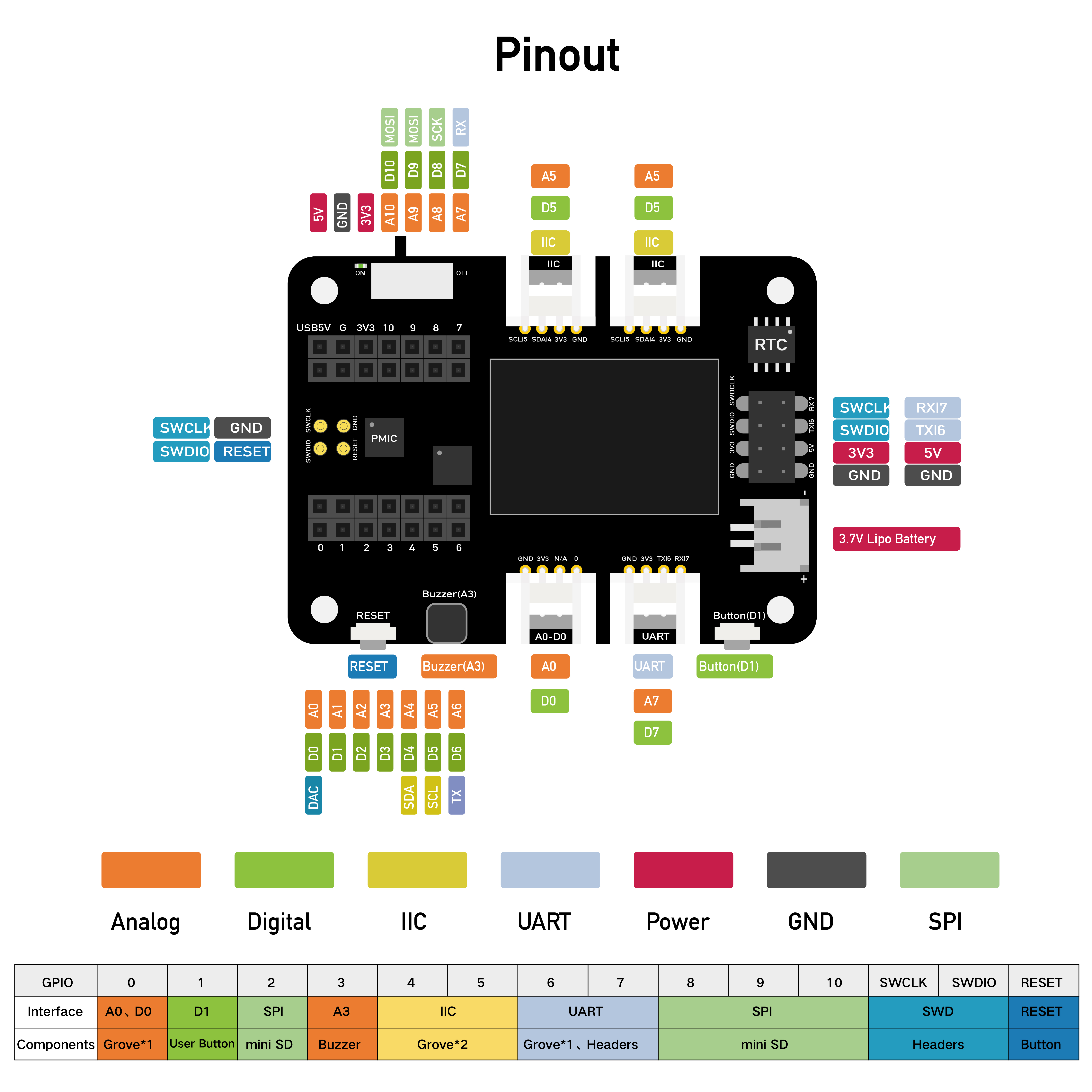
Pinout Diagram
External headers-pin description for Grove-Shield for Seeed Studio XIAO .
Expansion Board Usage
Connection
Put the Seeed Studio XIAO SAMD21 on the expansion board, the Seeed Studio XIAO SAMD21 green LED should light up.
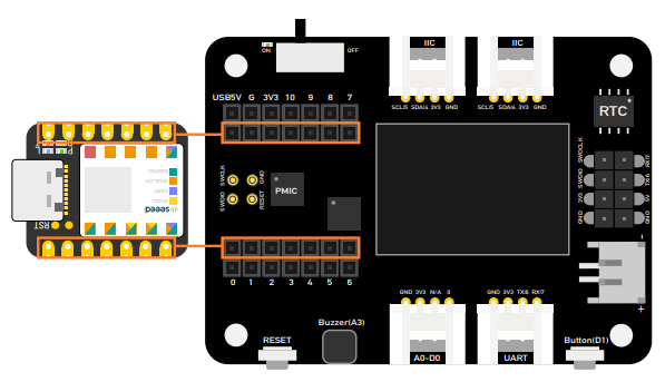
Please plug the Seeed Studio XIAO on the expansion board first, then plug Type-C, Remember pluing Seeed Studio XIAO into the middle of the two female header connectors, otherwise you will damage the Seeed Studio XIAO and the expansion board.
Battery usage
The Seeed Studio Expansion Base for XIAO can be powered by a battery, so if you do some demo that needs to be moved, that battery will help you to solve the power supply issue. when you plug the battery please watch out for the positive and negative anodes, follow the picture to connect the battery in case of damage the board.
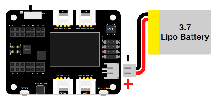
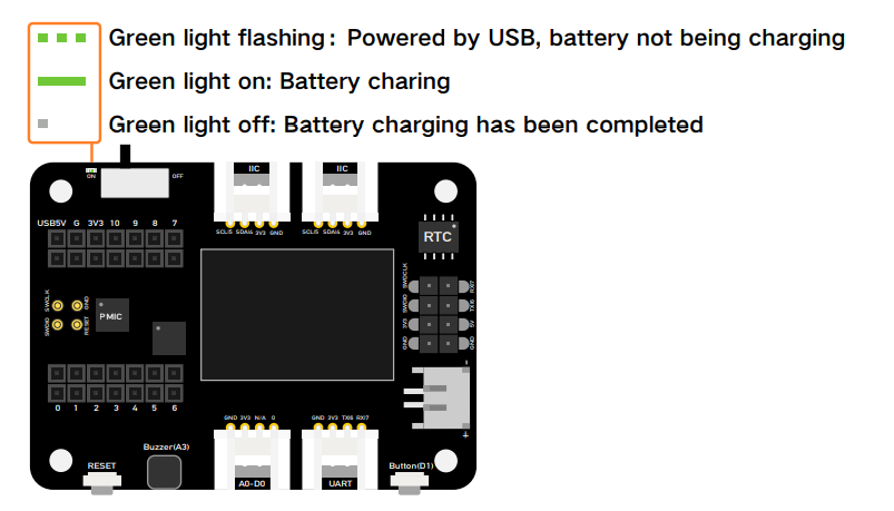
In addition, the board charged the battery when you plug the battery cable and the type-C cable and switch the button to on.
As the below picture, if the LED flashing which means the battery does not charge or the board does not connect battery if the LED keeps light on which is mean the battery is charging.
Modules on the expansion board
Rich peripherals on board including:
-
OLED display: Visual data display without connecting to PC, which enables debug in a more efficient way, and builds application such as a sensor hub, data monitor system, etc.
-
RESET button: No more jumper wire and short circuit, easy reset with just one click.
-
SWD debug: SWD pin led out as male pin header, making debugger connection and firmware download much easier.
-
High precision RTC: High precision real-time clock with battery backup, enable maintain accurate time when the main power is turned off.
-
Expandable memory: With a MicroSD card slot on the back, no worry on memory limit any more when adding libraries and using circuit python.
-
User button: Besides the RESET button, also provide with another user-defined button.
-
Passive buzzer: You could change the PMW frequency to award different beep sound to get a "buzzer music".
-
Grove connectors: All pin led out, plug and play grove connectors support common data protocols (Grove IIC2, Grove UART1, A0/D0 Grove*1)
-
Lipo Battery Charging: JST2.0mm standard lipo battery connector and battery management system, supports both USB and lipo battery power supply, and easy onboard battery recharge.
-
5V servo connector: 5V output led out to male header for 5V servo and sensor connection.

OLED Display
This example introduces how to use the OLED display on the Seeed Studio Expansion Base for XIAO.
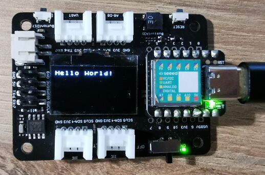
Step 1. Install the Seeed Studio XIAO SAMD21 on the Expansion board then conect the Type-C cable.
Step 2. Install the u8g2 library, this is the guide how to install the library.
Step 3. Copy the code and stick on the Ardiono IDE then upload it.
OLED Code
#include <Arduino.h>
#include <U8x8lib.h>
#include <Wire.h>

U8X8_SSD1306_128X64_NONAME_HW_I2C u8x8(/* reset=*/ U8X8_PIN_NONE, /* clock=*/ SCL, /* data=*/ SDA );   // OLEDs without Reset of the Display

void setup(void) {
  u8x8.begin();
  u8x8.setFlipMode(1);   // Enable (1) and disbale (0) 180 degree rotation of the display content
}

void loop(void) {
  u8x8.setFont(u8x8_font_chroma48medium8_r);
  u8x8.setCursor(0, 0);
  u8x8.print("Hello World!");
}
LED control by User Button
This example introduces how to use the button on the Seeed Studio Expansion Base for XIAO to control the LED on the Seeed Studio XIAO SAMD21.
Step 1. Install the Seeed Studio XIAO SAMD21 on the Expansion board then conect the Type-C cable.
Step 2. Open Arduino IDE, Copy the code and stick on the Ardiono IDE then upload it.
Code
const int buttonPin = 1;     // the number of the pushbutton pin
int buttonState = 0;         // variable for reading the pushbutton status

void setup() {
  // initialize the LED pin as an output:
  pinMode(LED_BUILTIN, OUTPUT);
  // initialize the pushbutton pin as an input:
  pinMode(buttonPin, INPUT_PULLUP);

}

void loop() {
  // read the state of the pushbutton value:
  buttonState = digitalRead(buttonPin);

  // check if the pushbutton is pressed. If it is, the buttonState is HIGH:
  if (buttonState == HIGH) {
    // turn LED on:
    digitalWrite(LED_BUILTIN, HIGH);
  } else {
    // turn LED off:
    digitalWrite(LED_BUILTIN, LOW);
  }

}
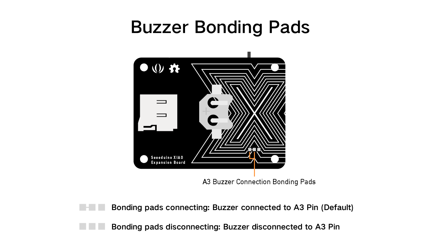
Buzzer
The Buzzer is default connected to the Pin A3, if you want to remove the buzzer function, just follow the below picture, cut off the line.
Play Song with Passive Buzzer
This example uses Buzzer on the Seeed Studio Expansion Base for XIAO to play Happy birthday.
Step 1. Install the Seeed Studio XIAO SAMD21 on the Expansion board then conect the Type-C cable.
Step 2. Open Arduino IDE, Copy the code and stick on the Ardiono IDE then upload it.
Code
int speakerPin = D3;
int length = 28; // the number of notes
char notes[] = "GGAGcB GGAGdc GGxecBA yyecdc";
int beats[] = { 2, 2, 8, 8, 8, 16, 1, 2, 2, 8, 8, 8, 16, 1, 2, 2, 8, 8, 8, 8, 16, 1, 2, 2, 8, 8, 8, 16 };
int tempo = 150;
void playTone(int tone, int duration) {
  for (long i = 0; i < duration * 1000L; i += tone * 2) {
    digitalWrite(speakerPin, HIGH);
    delayMicroseconds(tone);
    digitalWrite(speakerPin, LOW);
    delayMicroseconds(tone);
  }
}

void playNote(char note, int duration) {
  char names[] = {'C', 'D', 'E', 'F', 'G', 'A', 'B',
                  'c', 'd', 'e', 'f', 'g', 'a', 'b',
                  'x', 'y'
                 };
  int tones[] = { 1915, 1700, 1519, 1432, 1275, 1136, 1014,
                  956,  834,  765,  593,  468,  346,  224,
                  655 , 715
                };
  int SPEE = 5;

  // play the tone corresponding to the note name

  for (int i = 0; i < 16; i++) {
    if (names[i] == note) {
      int newduration = duration / SPEE;
      playTone(tones[i], newduration);
    }
  }
}

void setup() {
  pinMode(speakerPin, OUTPUT);
}

void loop() {
  for (int i = 0; i < length; i++) {
    if (notes[i] == ' ') {
      delay(beats[i] * tempo); // rest
    } else {
      playNote(notes[i], beats[i] * tempo);
    }
    // pause between notes
    delay(tempo);
  }
}
Servo Control by Rotary Angle Sensor
This example uses a rotary angle sensor to control servo via integration ports on the Seeed Studio Expansion Base for XIAO.
Step 1. Install the Seeed Studio XIAO SAMD21 on the Expansion board then conect the Type-C cable.
Step 2. Connect the Servo cable to I2C port, rotary angle sensor to D0.
Step 3. Open Arduino IDE, Copy the code and stick on the Ardiono IDE then upload it.
If your Development Board is XIAO ESP32 Series. Before you run the following code, you need to install ESP32Servo library first in Arduino Library Manager and change the following code from #include <Servo.h> to #include <ESP32Servo.h>.
#include <Servo.h>
#include <Arduino.h>
#include <Wire.h>

#define ROTARY_ANGLE_SENSOR A0
#define ADC_REF 3 //reference voltage of ADC is 3v.If the Vcc switch on the seeeduino
#define GROVE_VCC 3 //VCC of the grove interface is normally 3v
#define FULL_ANGLE 300 //full value of the rotary angle is 300 degrees

Servo myservo;  // create servo object to control a servo
// twelve servo objects can be created on most boards

int pos = 0;    // variable to store the servo position

void setup() {
  Serial.begin(9600);
  pinMode(ROTARY_ANGLE_SENSOR, INPUT);
  myservo.attach(5);  // attaches the servo on pin 9 to the servo object
}

void loop() {

  float voltage;
  int sensor_value = analogRead(ROTARY_ANGLE_SENSOR);
  voltage = (float)sensor_value * ADC_REF / 1023;
  float degrees = (voltage * FULL_ANGLE) / GROVE_VCC;
  Serial.println("The angle between the mark and the starting position:");
  Serial.println(degrees);
  delay(50);
  myservo.write(degrees);
}
RTC clock display
This example uses RTC to display the clock on the OLED.
Step 1. Install the Seeed Studio XIAO SAMD21 on the Expansion board then conect the Type-C cable.
Step 2. Install the u8g2 and PCF8563 library, this is the guide how to install the library.
Step 3. Copy the code and stick on the Ardiono IDE then upload it.
#include <Arduino.h>
#include <U8x8lib.h>
#include <PCF8563.h>
PCF8563 pcf;
#include <Wire.h>

U8X8_SSD1306_128X64_NONAME_HW_I2C u8x8(/* reset=*/ U8X8_PIN_NONE, /* clock=*/ SCL, /* data=*/ SDA );   // OLEDs without Reset of the Display

void setup() {
  Serial.begin(115200);
  u8x8.begin();
  u8x8.setFlipMode(1);
  Wire.begin();
  pcf.init();//initialize the clock
  pcf.stopClock();//stop the clock
  pcf.setYear(20);//set year
  pcf.setMonth(10);//set month
  pcf.setDay(23);//set dat
  pcf.setHour(17);//set hour
  pcf.setMinut(33);//set minut
  pcf.setSecond(0);//set second
  pcf.startClock();//start the clock
}

void loop() {
  Time nowTime = pcf.getTime();//get current time
  u8x8.setFont(u8x8_font_chroma48medium8_r);   // choose a suitable font

  u8x8.setCursor(0, 0);
  u8x8.print(nowTime.day);
  u8x8.print("/");
  u8x8.print(nowTime.month);
  u8x8.print("/");
  u8x8.print("20");
  u8x8.print(nowTime.year);
  u8x8.setCursor(0, 1);
  u8x8.print(nowTime.hour);
  u8x8.print(":");
  u8x8.print(nowTime.minute);
  u8x8.print(":");
  u8x8.println(nowTime.second);
  delay(1000);
}
SD card Function
For the XIAO SAMD21, XIAO RP2040, XIAO ESP32C3 and XIAO ESP32S3, you do not need to install a separate SD card library to use a third party. This procedure below is applicable to these XIAOs.
The expansion board circuit is designed so that the CS pin of the SD card slot is connected to the D2 pin of the XIAO.
#include <SPI.h>
#include <SD.h>
#include "FS.h"

File myFile;

void setup() {
  // Open serial communications and wait for port to open:
  Serial.begin(115200);
  while(!Serial);              // Execute after turning on the serial monitor
  delay(500);

  Serial.print("Initializing SD card...");

  pinMode(D2, OUTPUT);          // Modify the pins here to fit the CS pins of the SD card you are using.
  if (!SD.begin(D2)) {
    Serial.println("initialization failed!");
    return;
  }
  Serial.println("initialization done.");

  // open the file. note that only one file can be open at a time,
  // so you have to close this one before opening another.
  myFile = SD.open("/test.txt", FILE_WRITE);          // The path to read and write files needs to start with "/"

  // if the file opened okay, write to it:
  if (myFile) {
    Serial.print("Writing to test.txt...");
    myFile.println("testing 1, 2, 3.");
    // close the file:
    myFile.close();
    Serial.println("done.");
  } else {
    // if the file didn't open, print an error:
    Serial.println("error opening test.txt");
  }

  // re-open the file for reading:
  myFile = SD.open("/test.txt");                       // The path to read and write files needs to start with "/"
  if (myFile) {
    Serial.println("test.txt:");

    // read from the file until there's nothing else in it:
    while (myFile.available()) {
      Serial.write(myFile.read());
    }
    // close the file:
    myFile.close();
  } else {
    // if the file didn't open, print an error:
    Serial.println("error opening test.txt");
  }
}

void loop() {
  // nothing happens after setup
}
If you are using the XIAO nRF52840 series then you may need to download the SdFat library separately in order to use the SD card function.
#include <SPI.h>
#include "SdFat.h"
SdFat SD;

#define SD_CS_PIN D2
File myFile;

void setup() {
  // Open serial communications and wait for port to open:
  Serial.begin(9600);
  while (!Serial) {
    ; // wait for serial port to connect. Needed for native USB port only
  }


  Serial.print("Initializing SD card...");

  if (!SD.begin(SD_CS_PIN)) {
    Serial.println("initialization failed!");
    return;
  }
  Serial.println("initialization done.");

  // open the file. note that only one file can be open at a time,
  // so you have to close this one before opening another.
  myFile = SD.open("/test.txt", FILE_WRITE);

  // if the file opened okay, write to it:
  if (myFile) {
    Serial.print("Writing to test.txt...");
    myFile.println("testing 1, 2, 3.");
    // close the file:
    myFile.close();
    Serial.println("done.");
  } else {
    // if the file didn't open, print an error:
    Serial.println("error opening test.txt");
  }

  // re-open the file for reading:
  myFile = SD.open("test.txt");
  if (myFile) {
    Serial.println("test.txt:");

    // read from the file until there's nothing else in it:
    while (myFile.available()) {
      Serial.write(myFile.read());
    }
    // close the file:
    myFile.close();
  } else {
    // if the file didn't open, print an error:
    Serial.println("error opening test.txt");
  }
}

void loop() {
  // nothing happens after setup
}
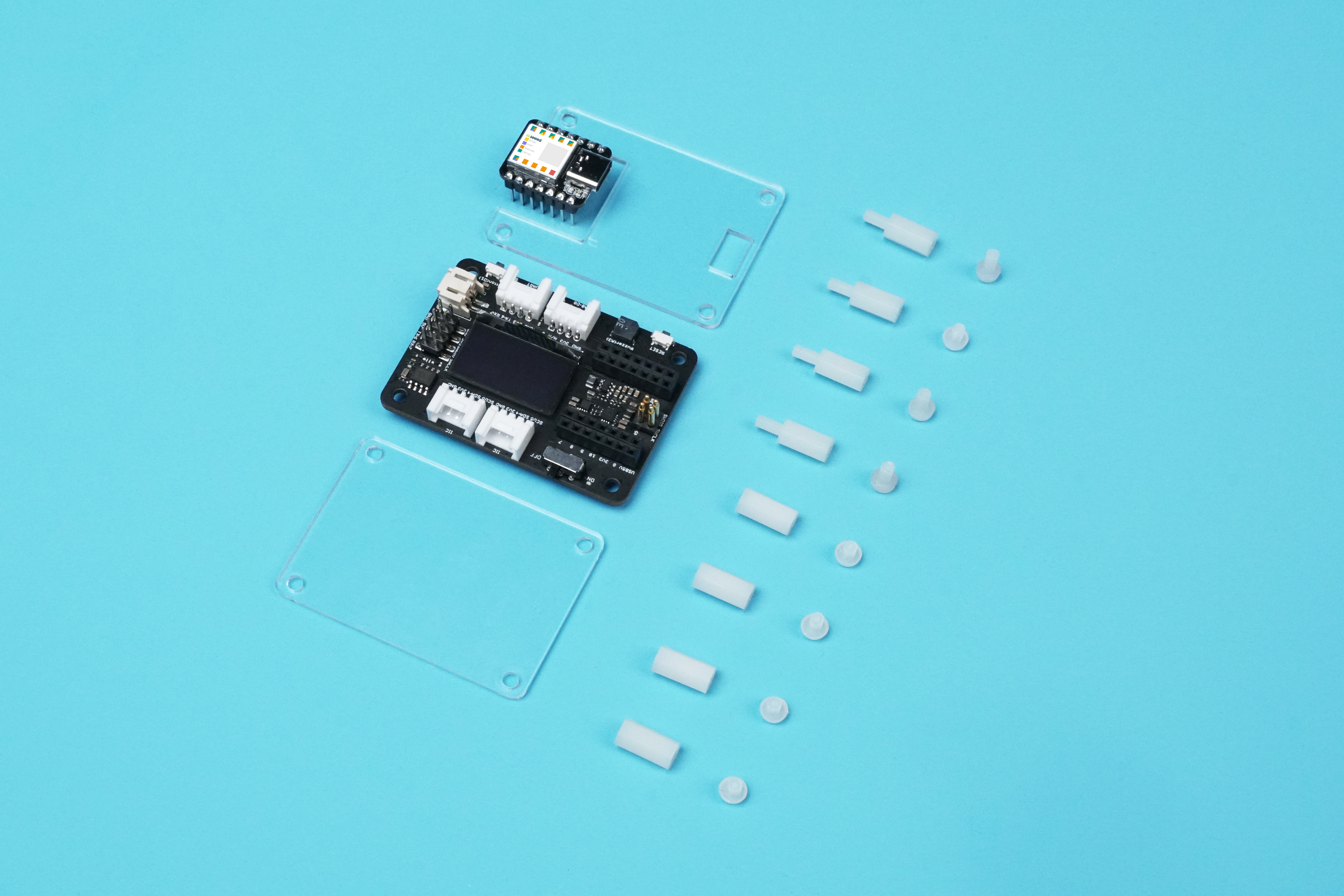
Acrylic Case for Seeed Studio Seeed Studio Expansion Base for XIAO
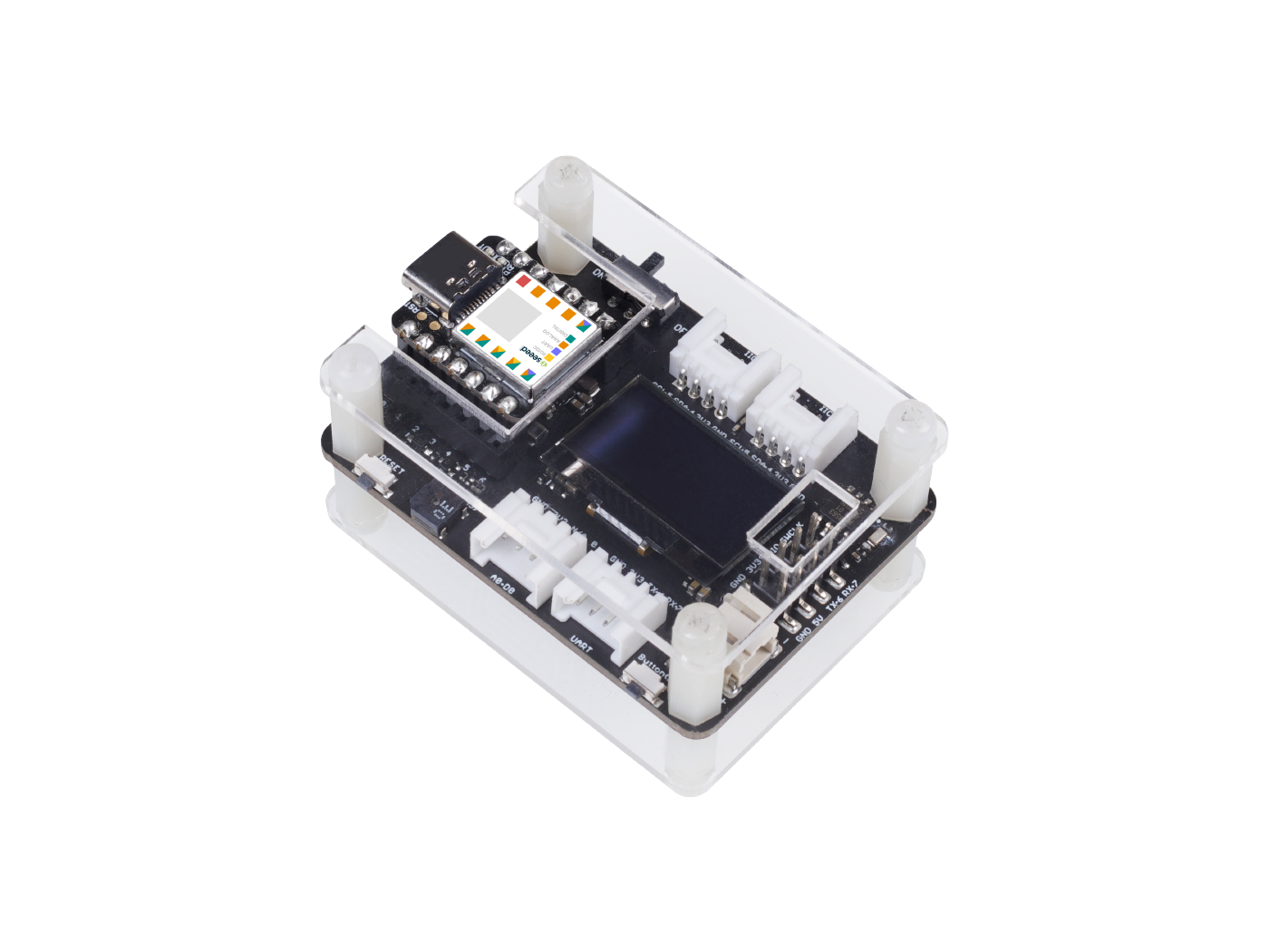

We made this acrylic case for protecting the Seeed Studio Expansion Base for XIAO, those are acrylic case components.
Compare with the Grove Shield for Seeed Studio XIAO , the Seeed Studio Expansion Base for XIAO added a lot useful modules for the users.
This Acrylic case easy to build it up and it also can dress the case look neater.

Circuitpython on Seeed Studio XIAO SAMD21 with expansion board
This wiki introduce how to install and run the official CircuitPython by Adafruit Industries on the Seeed Studio XIAO SAMD21 development board !
CircuitPython is a programming language designed to simplify experimenting and learning to program on low-cost microcontroller boards. It makes getting started easier than ever with no upfront desktop downloads needed. Once you get your board set up, open any text editor, and get started editing code. For more info, please refer to here.
Installing CircuitPython
Step 1. Install the Seeed Studio XIAO SAMD21 on the Expansion board then conect the Type-C cable.
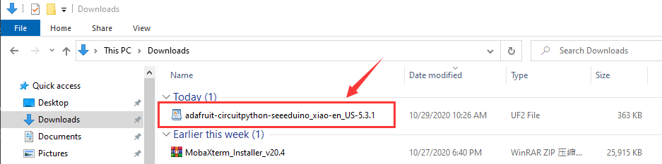
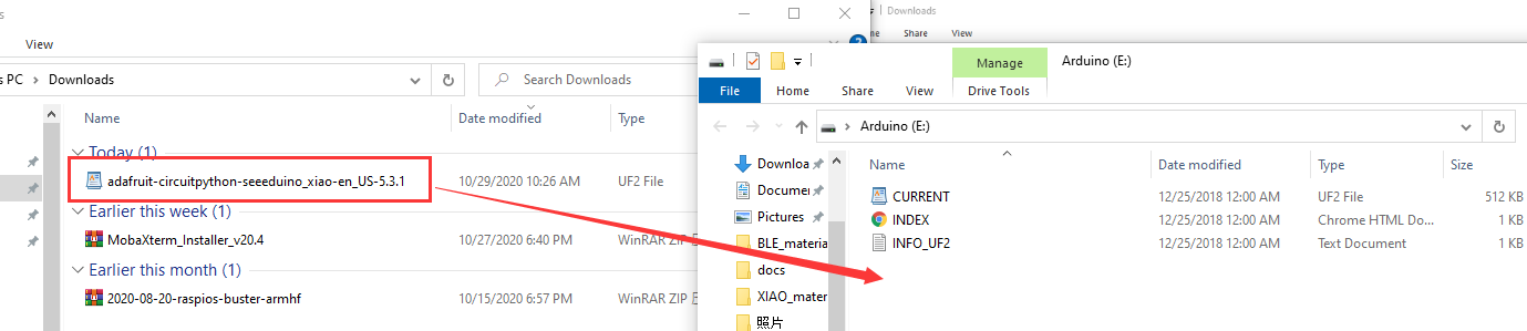
Step 2. Download the official **CircuitPython Bootloader for Seeed Studio XIAO SAMD21 **. A .uf2 , the flie will be store in your PC download.
Step 3. Entering the DFU bootloader mode by press the reset button twice quickly on the Seeed Studio Expansion Base for XIAO, then your PC will appear Arduino drive.
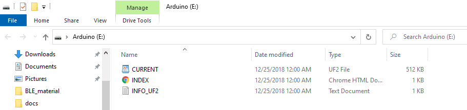
Step 4. An external drive named Arduino should appear in your PC. Drag the downloaded CircuitPython uf2 files to the Arduino drive.
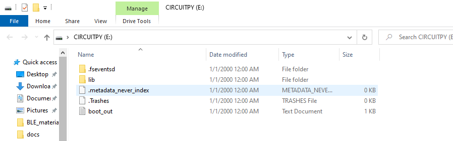
Step 5. Once loaded the CircuitPython bootloader, unplug the USB Type-C and re-connect. A new external drive called CIRCUITPY should be appear.
Step 6. Now, CircuitPython is loaded on Seeed Studio XIAO SAMD21 ! All you need to do it's to write you python program and name it main.py and drag it onto the CIRCUITPY drive.
CircuitPython Blink example
There is a simple example introduce how to use the CirsuitPython on the Seeed Studio XIAO .
Step 1 Create a txt file name main on the CIRCUITPY drive.
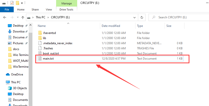
The main name is one of these: code.txt, code.py, main.py, main.txt, there is more detail about this behavior.
Step 2 Use REPL to get the pins of the orange LED. For details on REPL, see Welcome to CircuitPython! To use REPL, you first need to connet to the serial console. Once the connection is established, press CTRL+C twice to enter edit mode. Then, copy the following code and enter respectively.
>>> import board
>>> dir(board)
You will see a list of all the pins on your board that are available for you to use in your code. Each board will differ slightly depending on the number of pins available.

Do you see YELLOW_LED_INVERTED? That's the pin you used to blink the orange LED!
Step 3 Paste the code on the main file then save it, you will see the orange LED blinking on the Seeed Studio XIAO SAMD21 board.
Code
import time
import board
from digitalio import DigitalInOut, Direction

led = DigitalInOut(board.YELLOW_LED_INVERTED)
led.direction = Direction.OUTPUT

while True:
    led.value = True
    time.sleep(1)
    led.value = False
    time.sleep(1)
MicroSD card for circuitpython
The Seeed Studio XIAO SAMD21 build-in about 40 KB flash, but it may have not enough space to store the large size python code file, fortunately, Seeed Studio XIAO SAMD21 Expansion board built-in an MicroSD card slot for extending the store space, so you can follow this instruction to learn how to run the circuitpython on the MicroSD card.
The MicroSD card system format is FAT or exFAT. If you use other MicroSD card system format that will cause the MicroSD card can not be recognized.
Step 1. Prepare a micro SD Card to plug in the Seeed Studio XIAO SAMD21 expansion board.
Step 2. Assume you do not download the circuitPython file yet, please refer to Installing CircuitPython chapter.
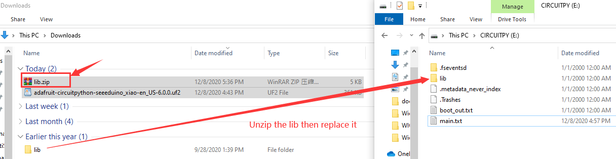
Step 3. Download lib unzips the file, then replace it with the new lib in the CIRCUITPY.
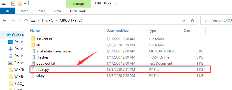
Step 4. Download the main.py file in the CIRCUITPY drive.
The main.py code
import sd
f = open("/sd/hello.txt", "r")   ## read the file from SD card
print(f.read())
Step 5. Download the sd.py file in the CIRCUITPY drive.
The sd.py code
import os
import adafruit_sdcard
import board
import busio
import digitalio
import storage
import sys

# Connect to the card and mount the filesystem for Seeed Studio XIAO .
spi = busio.SPI(board.SCK, board.MOSI, board.MISO)
cs = digitalio.DigitalInOut(board.D2)
sdcard = adafruit_sdcard.SDCard(spi, cs)
vfs = storage.VfsFat(sdcard)
storage.mount(vfs, "/sd")
sys.path.append("/sd")
sys.path.append("/sd/lib")  ## switch to the path to SD card
Buzzer Example
This example for test the buzzer via the run the buzzer.py in the MicroSD card.
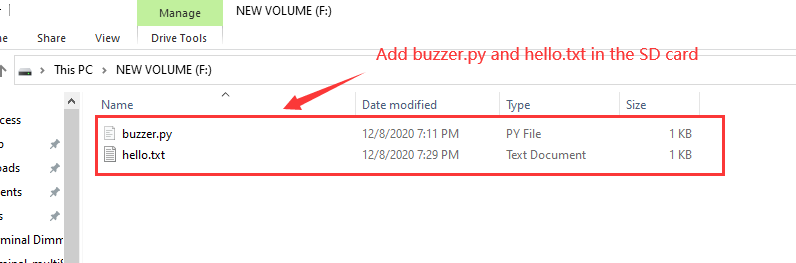
Step 1. You can just paste buzzer.py in the MicroSD card.
Step 2. Open main.py in the CIRCUITPY drive.
Step 3. Add import buzzer in the main.py file.
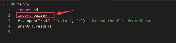
When you finish all the step, the buzzer will work. If you to run other python files in the MicroSD card, please imitate the example.
If you want back to Arduino mode, you just need to upload any programme on the Arduino IDE.
Demo
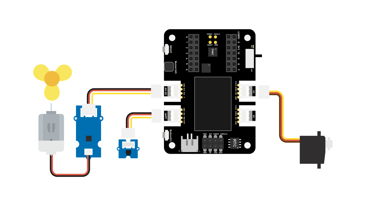
Project 1 - Remote control fan
Overview
This wiki introduce how to make a Mini fan to plase on your room keep cool.
Feature
- Automatic swing fan
Component required
Hardware Connection
Please follow the same color line to connect each sensor on the board. Please connect the fan grove cable to D0, servo grove cable to I2C, IR grove cable to D7.
Arduino Instructions
Step 1. Follow the connection picture connect all the sensor on the board.
Step 2. Install the Arduino-IRremote library, this is the guide how to install the library.
Step 3. Copy the code stick on the Aruino IDE then upload it.
Step 4. Place the Fan in the safety position, try to press the button make sure it can work safely.
Code
#include <IRremote.h>
#include <Servo.h>

Servo myservo;  // create servo object to control a servo
int RECV_PIN = 7; // set pin 2 as IR control

IRrecv irrecv(RECV_PIN);

decode_results results;

int pos = 90;    // variable to store the servo position
int fanPin = 0;  // set D6 as control switch
int fanState = LOW;
int IO = 0;

void setup()
{
  Serial.begin(9600);
  Serial.println("Enabling IRin");  // remind enabling IR
  irrecv.enableIRIn(); // Start the receiver
  Serial.println("Enabled IRin");
  myservo.attach(5);  // attaches the servo on pin 2 to the servo object
  pinMode(fanPin, OUTPUT);

}

void loop() {
  if (irrecv.decode(&results)) { //checking IR signal
    if (results.value == 2155829415) {    // Power off/on
      IO++;
      if (IO % 2 == 0) {
        fanState = HIGH;
        digitalWrite(fanPin, fanState);
        delay(100);
      }
      else {
        fanState = LOW;
        digitalWrite(fanPin, fanState);
        delay(100);
      }
    }

    if (results.value == 2155821255 ) {    // fan swing to left
      for (pos; pos <= 89; pos += 1) { // goes from 0 degrees to 90 degrees
        // in steps of 1 degree
        myservo.write(pos);              // tell servo to go to position in variable 'pos'

        delay(40);                       // waits 15ms for the servo to reach the position
        if (irrecv.decode(&results)) {
          irrecv.resume();
          if (results.value == 2155870215)
            break;
        }
      }
    }

    if (results.value == 2155870215 ) {    // fan swing to right
      for (pos; pos >= 1; pos -= 1) { // goes from 90 degrees to 0 degrees
        myservo.write(pos);              // tell servo to go to position in variable 'pos'
        delay(40);                       // waits 15ms for the servo to reach the position

        if (irrecv.decode(&results)) {
          irrecv.resume();
          if (results.value == 2155821255)
            break;
        }
      }
    }
    Serial.println(pos);
    Serial.println(results.value, HEX);
    Serial.println(results.value);
    irrecv.resume();                    //recive next intrustion
  }
  delay(100);
}
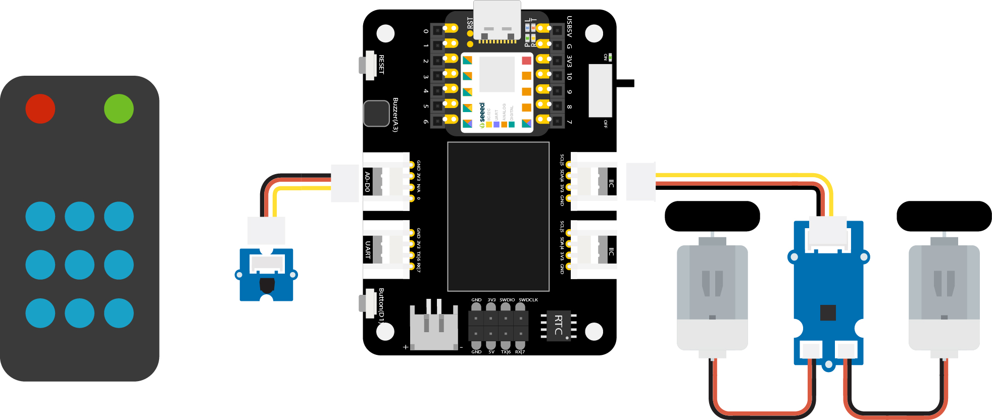
Project 2 - Remote control car
Overview
This wiki introduce how to make a remote control car.
Feature
- Mini size car easy to across the narrow road
Component required
Hardware Connection
Please follow the same color line to connect each sensor on the board. Please connect the IR sensor grove cable to D0, Mini Motor Driver grove cable to I2C.
Arduino Instructions
Step 1. Follow the connection picture connect all the sensor on the board.
Step 2. Download the Aruidno IDE
Step 3. Install the Arduino-IRremote and Motor driver library, this is the guide how to install the library.
Step 4. Copy the code stick on the Aruino IDE then upload it.
Code
#include <Arduino.h>
#include <U8g2lib.h>
#include <IRremote.h>
#include <SparkFunMiniMoto.h>  // Include the MiniMoto library
// Create two MiniMoto instances, with different address settings.
MiniMoto motor0(0xC4); // A1 = 1, A0 = clear
MiniMoto motor1(0xC0); // A1 = 1, A0 = 1 (default)

#define FAULTn  1     // Pin used for fault detection.

int RECV_PIN = 0; // set pin 2 as IR control
IRrecv irrecv(RECV_PIN);
decode_results results;

void setup() {
  Serial.begin(9600);
  Serial.println("Enabling IRin");  // remind enabling IR
  irrecv.enableIRIn(); // Start the receiver
  pinMode(FAULTn, INPUT);
}

void loop() {
  if (irrecv.decode(&results)) { //checking IR signal
    if (results.value == 2155862055) {
      //Forward  2155862055
      motor0.drive(-600);
      motor1.drive(600);
      delayUntil(20);
    }
    if (results.value == 2155813095) {
      //Brake   2155813095
      motor0.brake();
      motor1.brake();
      delay(100);
    }
    if (results.value == 2155823295) {
      //backward  2155823295
      motor0.drive(600);
      motor1.drive(-600);
      delayUntil(20);
    }
    if (results.value == 2155829415) {
      //Stop  2155829415
      motor0.stop();
      motor1.stop();
      delay(100);
    }
    if (results.value == 2155821255) {
      //turn right   2155821255
      motor0.drive(600);
      motor1.drive(600);
      delayUntil(20);
    }
    if (results.value == 2155837575) {
      //turn left    2155837575
      motor0.drive(-600);
      motor1.drive(-600);
      delayUntil(20);
    }
    irrecv.resume();                    //recive next intrustion

  }
  delay(100);
}

void delayUntil(unsigned long elapsedTime) {
  unsigned long startTime = millis();
  while (startTime + elapsedTime > millis()) {
    if (digitalRead(FAULTn) == LOW) {
      byte result = motor0.getFault();
      result = motor1.getFault();
    }
  }
}
Project 3 - Fingerprint unlocks treasure box -Seeed Studio XIAO
Overview
This box can store your important stuff, and you are not worried about some people will take your thing, the box has the fingerprint function to protecting your thing, and if the fingerprint authorization failed, the buzzer will alarm and the LED ring will display the red colour, only your finger has registered on the board when the begin, then put your finger on the board, when fingerprint pass the authorization, the LED ring will display green colour.
Feature
- Easy to record your fingerprint
- LED ring can remind you the lock state
- The OLED screen can display the current information
- The buzzer can remind you the fingerprint whether pass authorization
Component required
Hardware Connection
Please connect each module on the board as shown in the picture. Connect the fingerprint module to the UART port of the XIAO expansion board, and connect the servo to the D0 port of the XIAO expansion board.
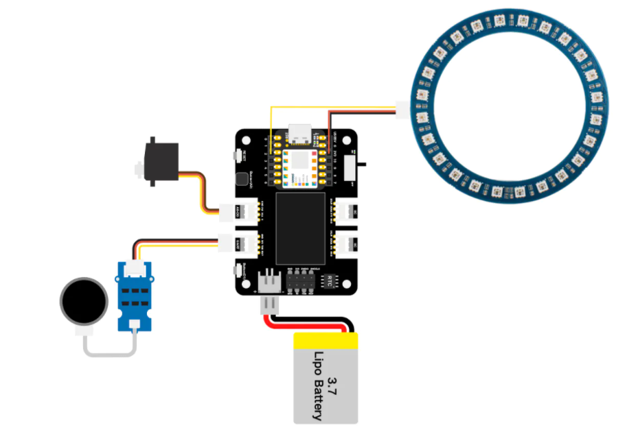
Note that the NeoPixel ring is directly connected to the pins of the XIAO development board through three different colored wires: Connect the DIN pin of the NeoPixel ring with the yellow wire to the D1 pin of the XIAO, connect the VIN pin of the NeoPixel ring with the red wire to the 3V3 pin of the XIAO, and connect the GND pin of the NeoPixel ring with the black wire to the GND pin of the XIAO.

Arduino Instructions
Step 1. Follow the connection picture connect all the sensor on the board.
Step 2. Download the Aruidno IDE
Step 3. Install the u8g2, Servo, Seeed_Arduino_KCT202 and Seeed_LED_Ring library, this is the guide how to install the library.
Step 4. Copy the code stick on the Aruino IDE then upload it.
Demonstration
- Record your fingerprint
The screen will display finger recording at the begin, you just need to put your finger on the finger device, after that, the program will analyze your fingerprint, then finish registered.
- Identity authorization(pass certification)
The screen will display "Please verify", you need to put your finger on the fingerprint device, then the LED ring will turn to green colour.
- Identity authorization(unpass certification)
If other people put their finger on it, the LED ring will turn to red colour and the board will display "Identity deny" meanwhile the alarm will be work.
Code
#include <Servo.h>
#include <Arduino.h>
#include <U8x8lib.h>
#include "ATSerial.h"
#include "Protocol.h"
#include "KCT202.h"
#include "Adafruit_NeoPixel.h"

#define PIXEL_PIN    2    // Digital IO pin connected to the NeoPixels.
#define PIXEL_COUNT 24
#define debug SerialUSB
#define uart  Serial1
FingerPrint_KCT202<Uart, Serial_> kct202;
Adafruit_NeoPixel strip = Adafruit_NeoPixel(PIXEL_COUNT, PIXEL_PIN, NEO_GRB + NEO_KHZ800);

Servo myservo;

Protocol_oprt oprt;
uint8_t err_code = 0;
uint8_t param[10];
uint32_t param_len;
int pos = 0;
const int buttonPin = 1;
int buttonState = 0;
int BuzzerPin = A3;

U8X8_SSD1306_128X64_NONAME_HW_I2C u8x8(/* reset=*/ U8X8_PIN_NONE);

void setup(void) {
  Serial.begin(115200);
  strip.setBrightness(255);
  strip.begin();
  strip.show(); // Initialize all pixels to 'off'
  colorWipe(strip.Color(125, 0, 125), 50);
  u8x8.begin();
  u8x8.setFlipMode(0);
  debug.begin(115200);
  pinMode(buttonPin, INPUT_PULLUP);
  pinMode(BuzzerPin, OUTPUT);
  kct202.begin(uart, debug);
  myservo.attach(0);
  myservo.write(0);
  kct202.autoRegisterFingerPrint(1, 4, LED_OFF_AFTER_GET_GRAGH | PRETREATMENT_GRAGH | NOT_RET_FOR_EVERY_STEP | OVERRIDE_CURR_FINGER_PRINT);

  u8x8.setFont(u8x8_font_chroma48medium8_r);
  u8x8.setCursor(0, 3);
  u8x8.print("finger recording");
  if (0 == kct202.getRegisterResponAndparse()) {
    debug.println("Register ok!");
    u8x8.setFont(u8x8_font_chroma48medium8_r);
    u8x8.setCursor(0, 3);
    u8x8.print("    be ready    ");
    delay(500);
    colorWipe(strip.Color(0, 125, 125), 50);
    u8x8.setCursor(0, 3);
    u8x8.print("   *** 3 ***    ");
    delay(500);
    u8x8.setCursor(0, 3);
    u8x8.print("   *** 2 ***    ");
    delay(500);
    u8x8.setCursor(0, 3);
    u8x8.print("   *** 1 ***    ");
    delay(500);
    u8x8.setCursor(0, 3);
    u8x8.print("   Registered");
    delay(800);
  }
}

void loop(void) {
  uint16_t finger_num = 0;

  kct202.autoVerifyFingerPrint(CHECK_ALL_FINGER_TEMP,
                               LED_OFF_AFTER_GET_GRAGH | PRETREATMENT_GRAGH | NOT_RET_FOR_EVERY_STEP);
  u8x8.setFont(u8x8_font_chroma48medium8_r);
  u8x8.setCursor(0, 3);
  u8x8.print(" Please verify  ");

  if (0 == kct202.getVerifyResponAndparse(finger_num)) {
    debug.println("Verify ok!");
    debug.print("Your finger temp id = ");
    debug.println(finger_num, HEX);
    colorWipe(strip.Color(0, 255, 30), 50);
    u8x8.setFont(u8x8_font_chroma48medium8_r);
    u8x8.setCursor(0, 3);
    u8x8.print("Identity comfirm");
    delay(800);

    analogWrite(BuzzerPin, 128);
    delay(100);
    analogWrite(BuzzerPin, 0);
    delay(100);
    analogWrite(BuzzerPin, 128);
    delay(100);
    analogWrite(BuzzerPin, 0);
    delay(100);

    for (pos = 0; pos <= 90; pos += 1) {
      myservo.write(pos);
      delay(15);
    }
    while (1) {
      //      pinMode(buttonPin, INPUT);
      buttonState = digitalRead(buttonPin);
      u8x8.setFont(u8x8_font_chroma48medium8_r);
      u8x8.setCursor(0, 3);
      u8x8.print("Please close    ");
      Serial.println(pos);
      Serial.println(buttonState);
      if (buttonState == LOW && pos == 91) {
        for (pos = 91; pos >= 0; pos -= 1) { // goes from 180 degrees to 0 degrees
          u8x8.setFont(u8x8_font_chroma48medium8_r);
          u8x8.setCursor(0, 3);
          u8x8.print("Lock closing    ");
          myservo.write(pos);              // tell servo to go to position in variable 'pos'
          delay(15);                       // waits 15ms for the servo to reach the position
        }
        colorWipe(strip.Color(255, 0, 0), 50);
        break;
      }
    }
  }

  else {
    colorWipe(strip.Color(255, 0, 0), 50);
    u8x8.setFont(u8x8_font_chroma48medium8_r);
    u8x8.setCursor(0, 3);
    u8x8.print(" Identity deny ");
    //    myservo.write(0);
    delay(200);

  analogWrite(BuzzerPin, 250);
  delay(2000);
    analogWrite(BuzzerPin, 0);
  delay(100);

    u8x8.setCursor(0, 3);
    u8x8.print("  Please retry  ");
    delay(1500);
  }
}

void colorWipe(uint32_t c, uint8_t wait) {
  for (uint16_t i = 0; i < strip.numPixels(); i++) {
    strip.setPixelColor(i, c);
    strip.show();
    delay(70);
  }
}
Project 4 - Seeed Studio Expansion Base for XIAO - mjolnir
Overview
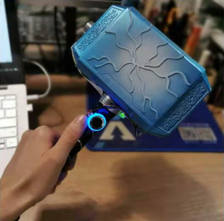
This hammer is simulated Mjolnir, you need you to record your fingerprint on this device then you will become its master. The hammer needs a magnet to adsorb on the grove - electromagnet until its master to unlock via fingerprint, the hammer can take away.
Component required
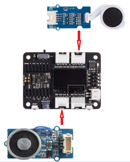
Hardware Connection
Please connect the expansion board and the required modules with Grove wire, connect the Grove electromagnet module to D0 port, and connect the fingerprint module to I2C port.
Arduino Instructions
Step 1. Follow the connection picture connect all the sensor on the board.
Step 2. Download the Aruidno IDE
Step 3. Install the u8g2 and Seeed_Arduino_KCT202 library, this is the guide how to install the library.
Step 4. Copy the code stick on the Aruino IDE then upload it.
Code
#include <U8x8lib.h>
#include "ATSerial.h"
#include "Protocol.h"
#include "KCT202.h"

#define debug SerialUSB
#define uart  Serial1
FingerPrint_KCT202<Uart, Serial_> kct202;

Protocol_oprt oprt;
uint8_t err_code = 0;
uint8_t param[10];
uint32_t param_len;

int Electromagnet = 0;

U8X8_SSD1306_128X64_NONAME_HW_I2C u8x8(/* reset=*/ U8X8_PIN_NONE);

// the setup routine runs once when you press reset:
void setup() {
  // initialize the digital pin as an output.

  u8x8.begin();
  u8x8.setFlipMode(0);
  debug.begin(115200);
  pinMode(Electromagnet, OUTPUT);
  digitalWrite(Electromagnet, HIGH);  // turn the Electromagnet on (HIGH is the voltage level)
  kct202.begin(uart, debug);
  kct202.autoRegisterFingerPrint(1, 4, LED_OFF_AFTER_GET_GRAGH | PRETREATMENT_GRAGH | NOT_RET_FOR_EVERY_STEP | OVERRIDE_CURR_FINGER_PRINT);
  u8x8.setFont(u8x8_font_chroma48medium8_r);
  u8x8.setCursor(0, 3);
  u8x8.print("finger recording");
  if (0 == kct202.getRegisterResponAndparse()) {
    u8x8.setFont(u8x8_font_chroma48medium8_r);
    u8x8.setCursor(0, 3);
    u8x8.print("    be ready    ");
    delay(500);
    u8x8.setCursor(0, 3);
    u8x8.print("   *** 3 ***    ");
    delay(500);
    u8x8.setCursor(0, 3);
    u8x8.print("   *** 2 ***    ");
    delay(500);
    u8x8.setCursor(0, 3);
    u8x8.print("   *** 1 ***    ");
    delay(500);
    u8x8.setCursor(0, 3);
    u8x8.print("   Registered");
    delay(800);
  }

}

  // the loop routine runs over and over again forever:
  void loop() {

    uint16_t finger_num = 0;
    kct202.autoVerifyFingerPrint(CHECK_ALL_FINGER_TEMP, LED_OFF_AFTER_GET_GRAGH | PRETREATMENT_GRAGH | NOT_RET_FOR_EVERY_STEP);
    u8x8.setFont(u8x8_font_chroma48medium8_r);
    u8x8.setCursor(0, 3);
    u8x8.print(" Please verify  ");

    if (0 == kct202.getVerifyResponAndparse(finger_num)) {
      u8x8.setFont(u8x8_font_chroma48medium8_r);
      u8x8.setCursor(0, 3);
      u8x8.print("Identity comfirm");
      delay(800);
      digitalWrite(Electromagnet, LOW);  // turn the Electromagnet on (HIGH is the voltage level)
      delay(5000);
      digitalWrite(Electromagnet, HIGH);
    }

    else {
      u8x8.setFont(u8x8_font_chroma48medium8_r);
      u8x8.setCursor(0, 3);
      u8x8.print(" Identity deny ");
      //    myservo.write(0);
      delay(200);

      u8x8.setCursor(0, 3);
      u8x8.print("  Please retry  ");
      delay(1500);
      digitalWrite(Electromagnet, HIGH);  // turn the Electromagnet on (HIGH is the voltage level)

    }
  }
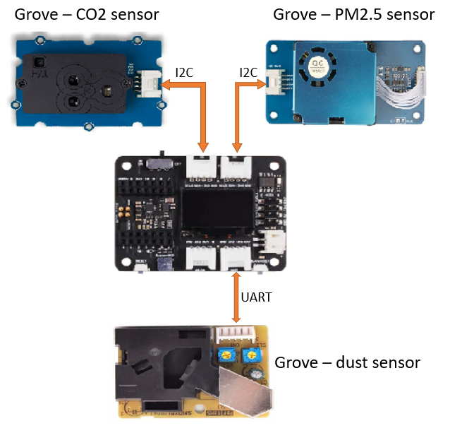
Project 5 - Air Quality Sensor Hub - Seeed Studio Expansion Base for XIAO
Overview
This is an environment detect device to collect PM2.5, PM10, temperature, humidity, CO2 and dust particle via Grove - Laser PM2.5 Sensor, Grove - CO2 & Temperature & Humidity sensor and Grove - dust Sensor respectively.
Component required
-
Seeed Grove - CO2 & Temperature & Humidity Sensor for Arduino (SCD30) - 3-in-1
-
Seeed Grove - Laser PM2.5 Dust Sensor - Arduino Compatible - HM3301
Hardware Connection
Please connect each sensor as shown in the diagram. Connect the CO2 sensor and PM2.5 sensor to two I2C ports respectively, and connect the Dust sensor to the UART port.
Arduino Instructions
Step 1. Follow the connection picture connect all the sensor on the board.
Step 2. Download the Aruidno IDE
Step 3. Install the u8g2, Seeed_PM2_5_sensor_HM3301 and Seeed_SCD30 library, this is the guide how to install the library.
Step 4. Copy the code stick on the Aruino IDE then upload it.
Code
#include <Arduino.h>
#include <U8x8lib.h>
#include <Seeed_HM330X.h>
#include "SCD30.h"

#define SERIAL_OUTPUT SerialUSB
#define SERIAL SerialUSB

int pin = 7;
unsigned long duration;
unsigned long starttime;
unsigned long sampletime_ms = 5000;//sampe 30s ;
unsigned long lowpulseoccupancy = 0;
float ratio = 0;
float concentration = 0;

const int buttonPin = 1;
int buttonState = 0;
int memu = 0;

U8X8_SSD1306_128X64_NONAME_HW_I2C u8x8(/* reset=*/ U8X8_PIN_NONE);
HM330X sensor;
uint8_t buf[30];

const char* str[] = {"sensor num: ", "PM1.0 concentration(CF=1,Standard particulate matter,unit:ug/m3): ",
                     "PM2.5 concentration(CF=1,Standard particulate matter,unit:ug/m3): ",
                     "PM10 concentration(CF=1,Standard particulate matter,unit:ug/m3): ",
                     "PM1.0 concentration(Atmospheric environment,unit:ug/m3): ",
                     "PM2.5 concentration(Atmospheric environment,unit:ug/m3): ",
                     "PM10 concentration(Atmospheric environment,unit:ug/m3): ",
                    };


///////////////////////////////////////////////////////////////////
//PM2.5 concentration(Atmospheric environment,unit:ug/m3): value
///////////////////////////////////////////////////////////////////
HM330XErrorCode print_result(const char* str, uint16_t value) {
  if (NULL == str) {
    return ERROR_PARAM;
  }
  //  SERIAL_OUTPUT.print(str);
  u8x8.setFont(u8x8_font_chroma48medium8_r);
  u8x8.setCursor(0, 0);
  u8x8.print("PM2.5: ");
  u8x8.setCursor(7, 0);
  u8x8.print(value);
  u8x8.setCursor(11, 0);
  u8x8.print("ug/m");
  Serial.println(value);
  return NO_ERROR;
}

HM330XErrorCode print_result_1(const char* str, uint16_t value) {
  if (NULL == str) {
    return ERROR_PARAM;
  }
  //  SERIAL_OUTPUT.print(str);
  u8x8.setFont(u8x8_font_chroma48medium8_r);
  u8x8.setCursor(0, 0);
  u8x8.print("PM10: ");
  u8x8.setCursor(7, 0);
  u8x8.print(value);
  u8x8.setCursor(11, 0);
  u8x8.print("ug/m");
  Serial.println(value);
  return NO_ERROR;
}

/*parse buf with 29 uint8_t-data*/
HM330XErrorCode parse_result(uint8_t* data) {
  uint16_t value = 0;
  if (NULL == data) {
    return ERROR_PARAM;
  }
  value = (uint16_t) data[6 * 2] << 8 | data[6 * 2 + 1];
  print_result(str[6 - 1], value);
  return NO_ERROR;
}


HM330XErrorCode parse_result2(uint8_t* data) {
  uint16_t value = 0;
  if (NULL == data) {
    return ERROR_PARAM;
  }
  value = (uint16_t) data[7 * 2] << 8 | data[7 * 2 + 1];
  print_result_1(str[7 - 1], value);
  return NO_ERROR;
}

////////////////////////////////////////////////////////////////////

/*30s*/
void setup() {
  Serial.begin(115200);
  Wire.begin();
  u8x8.begin();
  u8x8.setFlipMode(0);
  scd30.initialize();
  pinMode(pin, INPUT);
  pinMode(buttonPin, INPUT_PULLUP);
  starttime = millis();//get the current time;

}

void loop() {
  float result[3] = {0};
  duration = pulseIn(pin, LOW);
  lowpulseoccupancy = lowpulseoccupancy + duration;

  buttonState = digitalRead(buttonPin);

  if (buttonState == LOW) {
    memu++;
    delay(15);
    if (memu == 2) {
      memu = 0;
    }
  }
  Serial.println(memu);

  if (scd30.isAvailable() && memu == 0) {
    scd30.getCarbonDioxideConcentration(result);
    u8x8.setFont(u8x8_font_chroma48medium8_r);
    u8x8.setCursor(0, 3);
    u8x8.print("CO2: ");
    u8x8.setCursor(5, 3);
    u8x8.print(result[0]);
    u8x8.setCursor(12, 3);
    u8x8.print("pmm");
    delay(1000);
  }

  if (sensor.read_sensor_value(buf, 29) && memu == 0) {
    SERIAL_OUTPUT.println("HM330X read result failed!!!");
  }
  if(memu == 0){
  parse_result(buf);
  }

  if ((millis() - starttime) > sampletime_ms  && memu == 0) {
    ratio = lowpulseoccupancy / (sampletime_ms * 10.0); // Integer percentage 0=>100
    concentration = 1.1 * pow(ratio, 3) - 3.8 * pow(ratio, 2) + 520 * ratio + 0.62; // using spec sheet curve

    u8x8.setFont(u8x8_font_chroma48medium8_r);
    u8x8.setCursor(0, 6);
    u8x8.print("Dust: ");

    u8x8.setCursor(6, 6);
    u8x8.print(concentration);

    u8x8.setCursor(12, 6);
    u8x8.print("pcs");

    //    Serial.println(concentration);
    lowpulseoccupancy = 0;
    starttime = millis();
  }


  if (scd30.isAvailable() && memu == 1) {
    scd30.getCarbonDioxideConcentration(result);
    u8x8.setFont(u8x8_font_chroma48medium8_r);
    u8x8.setCursor(0, 3);
    u8x8.print("Temp: ");
    u8x8.setCursor(6, 3);
    u8x8.print(result[1]);
    u8x8.setCursor(10, 3);
    u8x8.print(" C   ");

    u8x8.setCursor(0, 6);
    u8x8.print("Humi: ");
    u8x8.setCursor(5, 6);
    u8x8.print(result[2]);
    u8x8.setCursor(8, 6);
    u8x8.print("  %     ");

    delay(1000);
  }

  if (sensor.read_sensor_value(buf, 29) && memu == 1) {
    SERIAL_OUTPUT.println("HM330X read result failed!!!");
  }
  if(memu == 1){
  parse_result2(buf);
  }
}
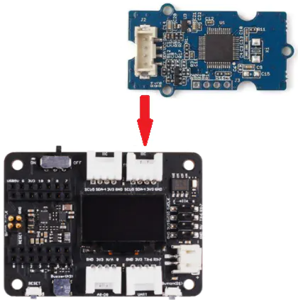
Project 6 - Seeed Studio Expansion Base for XIAO - Heart Rate
Overview
This simple and inexpensive project is based on the Seeed Studio Expansion Base for XIAO to report the heart rate. The device used has an I2C two-wire interface and therefore keeps the wiring down to a minimum.
Component required
Hardware Connection
As shown in the figure below, connect the heart rate sensor to the I2C interface of the XIAO expansion board.
Arduino Instructions
Step 1. Follow the connection picture connect all the sensor on the board.
Step 2. Download the Aruidno IDE
Step 3. Install the u8g2 library, this is the guide how to install the library.
Step 4. Copy the code stick on the Aruino IDE then upload it.
Code
#include <Arduino.h>
#include <U8x8lib.h>

#include <Wire.h>

U8X8_SSD1306_128X64_NONAME_HW_I2C u8x8(/* reset=*/ U8X8_PIN_NONE);

void setup() {
  Serial.begin(9600);
  Serial.println("heart rate sensor:");

  u8x8.begin();
  u8x8.setFlipMode(1);
  Wire.begin();
}
void loop() {
  Wire.requestFrom(0xA0 >> 1, 1);    // request 1 bytes from slave device
  while (Wire.available()) {         // slave may send less than requested
    unsigned char c = Wire.read();   // receive heart rate value (a byte)
    u8x8.setFont(u8x8_font_chroma48medium8_r);
//    u8x8.setCursor(0, 3);
//    u8x8.print("blood detecting ");
//    delay(10000);

    u8x8.setCursor(0, 3);
    u8x8.print("HeartRate: ");
    u8x8.setCursor(10, 3);
    u8x8.print(c);
    u8x8.setCursor(13, 3);
    u8x8.print("bpm");
    Serial.println(c);

  }
  delay(500);
}
Resources
- [PDF]ETA1038
- [PDF]ETA3410
- [PDF]ETA6003
- [PDF]PCF8563T
- [PDF]Seeed Studio Expansion Base for XIAO_v1.0_SCH_200824
- [SCH]Seeed Studio Expansion Base for XIAO_v1.0_200824
- [BRD]Seeed Studio Expansion Base for XIAO_v1.0_200824
FAQ
Q1: Does the PMIC on the XIAO Expansion board output power on the 5V pins?
The PMIC does not output power; the 5V is directly sourced from the USB. The current provided on the 5V pin is equivalent to the current available from the USB connection.
Tech Support & Product Discussion
Thank you for choosing our products! We are here to provide you with different support to ensure that your experience with our products is as smooth as possible. We offer several communication channels to cater to different preferences and needs.