24GHz mmWave Sensor - Human Static Presence Module Lite (MR24HPC1)
Introduction
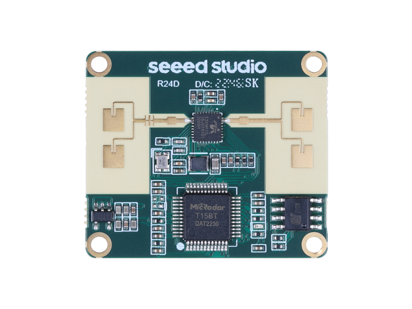
24GHz mmWave Sensor - Human Static Presence Module Lite is an antenna-integrated, health-friendly mmwave radar sensor that applies FMCW ranging technology, with operation in 24GHz, for implementation of human static presence, independently of environmental influences. This is also a personalized radar that users can configure underlying parameters of it to determine detected functions.
Application
- Automatically outdoor lighting
- Automaed door opening
- Whole house monitor
- Intelligent home appliances (TV, bath bully, security, etc.)
- Office energy (air conditioning, lighting)
- Sleep monitoring curve
- Home security
- IPC trigger
Features
- Human presence mmwave radar: Apply FMCW ranging technology, with operation in 24GHz and 5 meters detection range, for detecting human behavior in the sensing area
- Personalized radar detection: Provide configurable detection range, motion trigger, state change time, as well as visual debugging software to meet the requirements of various scenarios
- Health-friendly working status: Output power as low as harmless to the human body
- High immunity against interferences: Output data independently of environmental influences like temperature, humidity, noise, airflow, dust, light
- Arduino support
Hardware Overview
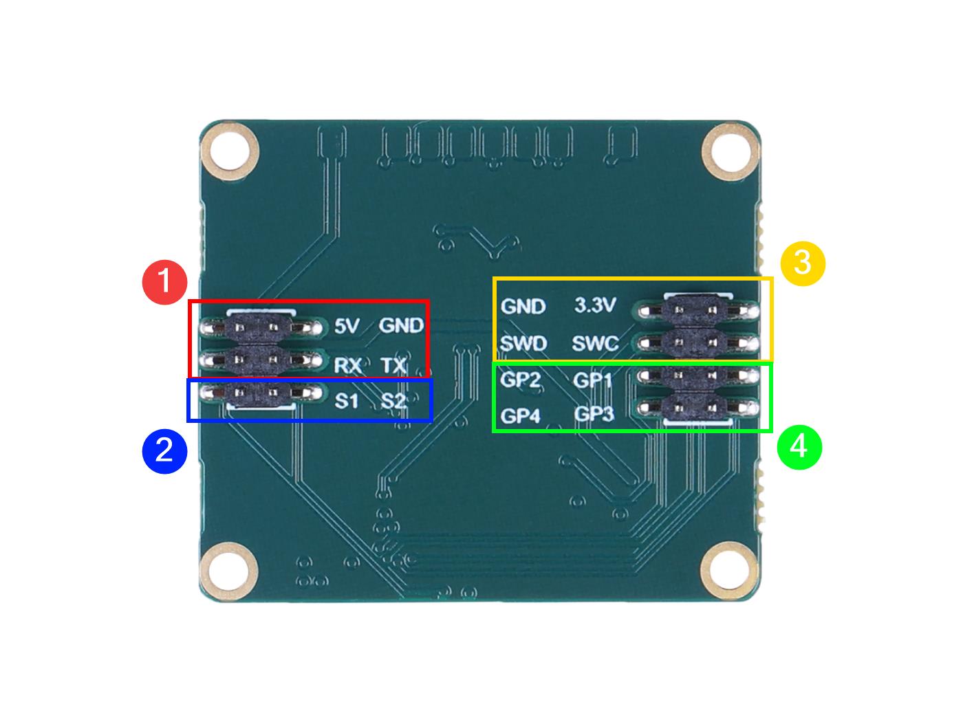
- The 5V pin is the power supply interface for the radar and RX and TX are the data transmission interfaces for the radar. RX means serial receive and TX means serial transmit.
- The human presence status output interface. You can use the level of these two pins to determine the current human movement in the environment. S1 output: high level - occupied, low level - unoccupied. S2 output: high level - active, low level - stationary.
- Flash firmware pinout.
- Overhead input/output pins.
Getting Started
Firmware Version Updates
The mmwave sensor has undergone a long period of technical precipitation and valuable suggestions provided by users, and we have been iterating on the original product to provide more accurate and reliable monitoring results and a better experience for our users.
Newly shipped sensors are shipped with the latest firmware by default to ensure the latest product experience. However, for the sake of the old user experience, we hereby provide the latest firmware and update method to ensure that you can use our latest technology.
Universal method - use J-link to burn firmware
If you encounter the wrong firmware or radar anomaly, firmware malfunction, etc., using this method to re-flash the firmware is the most effective way.
Download of the latest firmware
| Firmware Version | Download Address |
|---|---|
| Jlink_MR24HPC1-20230302.bin | Download |
-
Please check the function of your product carefully, please do not mix with other mmwave sensors to brush this firmware, otherwise it may cause abnormal product function, the consequences need to be your own responsibility!
-
Please also note that different ways of updating the firmware use different firmware content, what you are downloading is the firmware burned via J-link.
To update your radar to the latest version
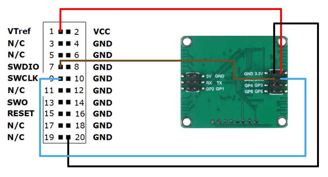
Step 1. You will need to have a Jlink and MR24HPC1 24GHz mmWave Sensor.
Connect the radar and Jlink together via Dupont wire as shown in the diagram below.
Step 2. Download the necessary software and firmware.
| File | Download Address |
|---|---|
| JlinkV644e.rar | Download |
| Pack_Segger_AT32F4xx_v1.3.3.zip | Download |
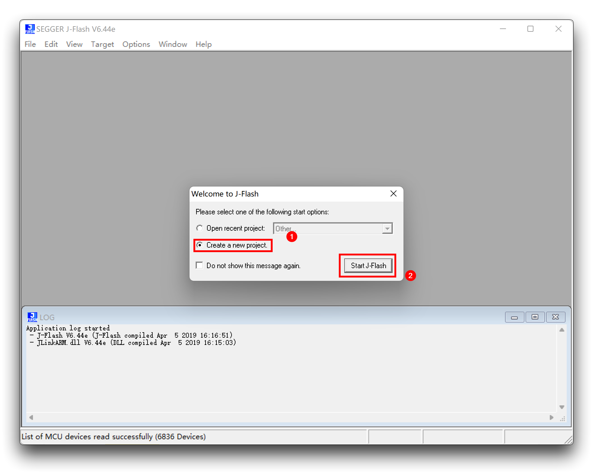
Step 3. Unzip JlinkV644e.rar and open the JLink_Windows_V644e.exe file inside.
Just follow the default options to install. Once the installation is complete, start the J-Flash V6.44e software.
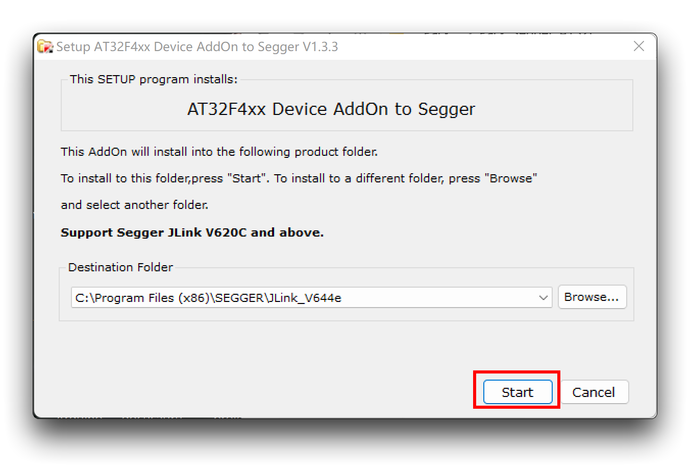
Step 4. Install the chip package.
Unzip Pack_Segger_AT32F4xx_v1.3.3.zip and open Segger_AT32F4xx_AddOn.exe inside.
If you meet error like the picture below when adding something to JFlash, you can follow the instruction below to solve the problem.
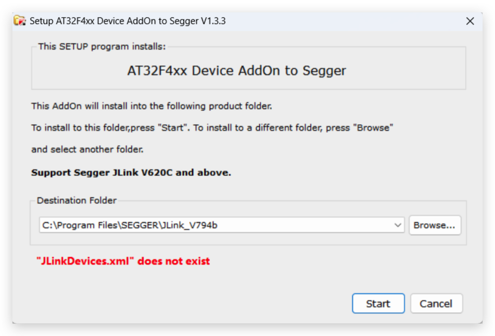
Solution:
-
Download this file from https://www.arterychip.com/en/product/AT32F403A.jsp
-
Unzip the file and open
-
Copy JLinkDevices.xml from C:\Program Files\SEGGER\JLink_V794 to C:\Users[User]\AppData\Roaming\SEGGER
This fixes the problem and we can flash with JFlash or JFlash Lite software.
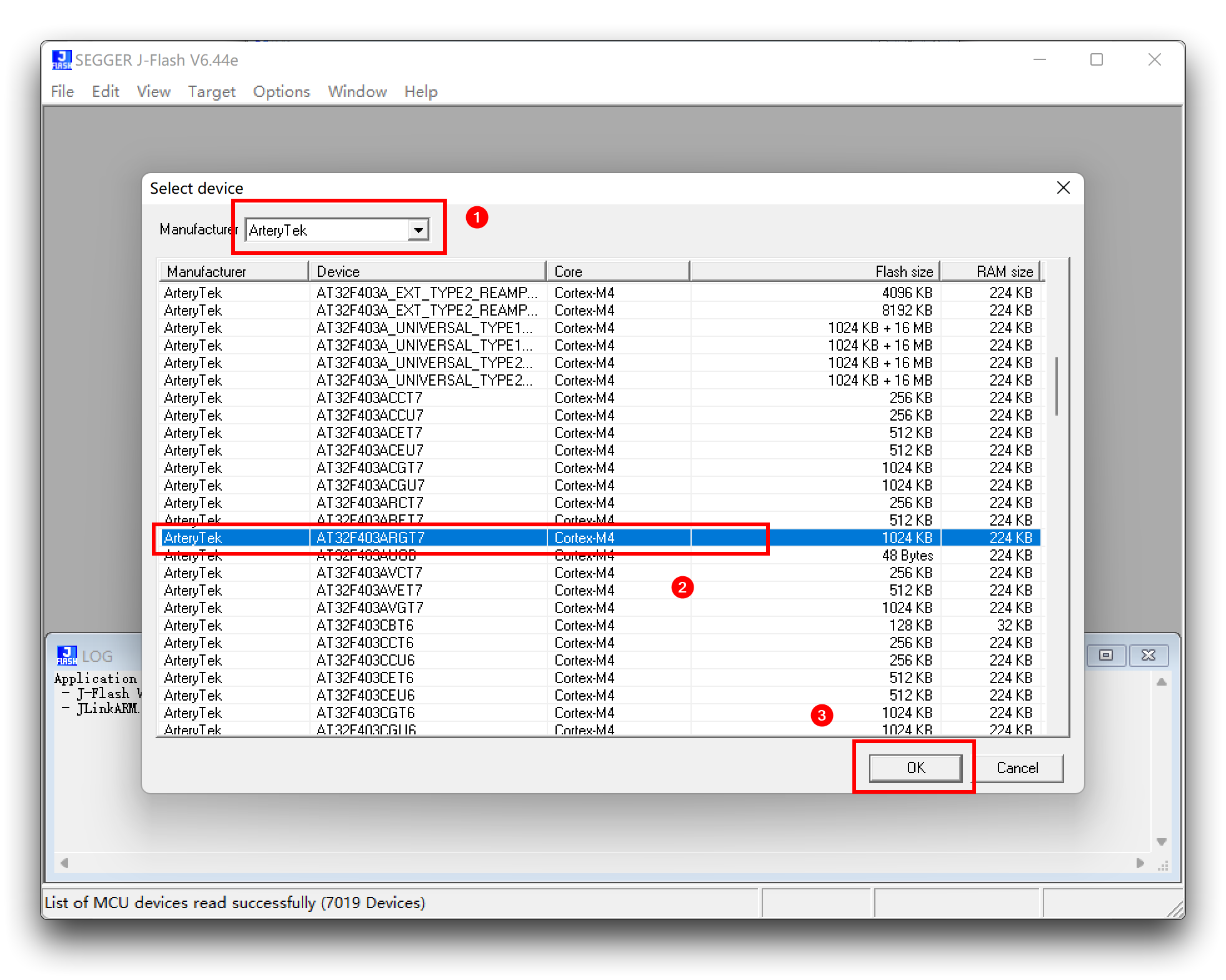
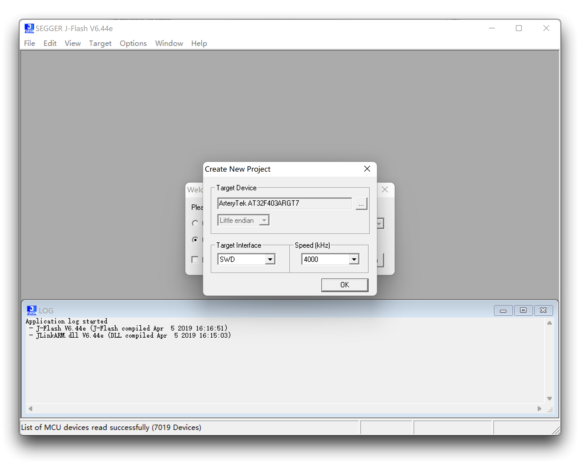
Step 5. Create a new project.
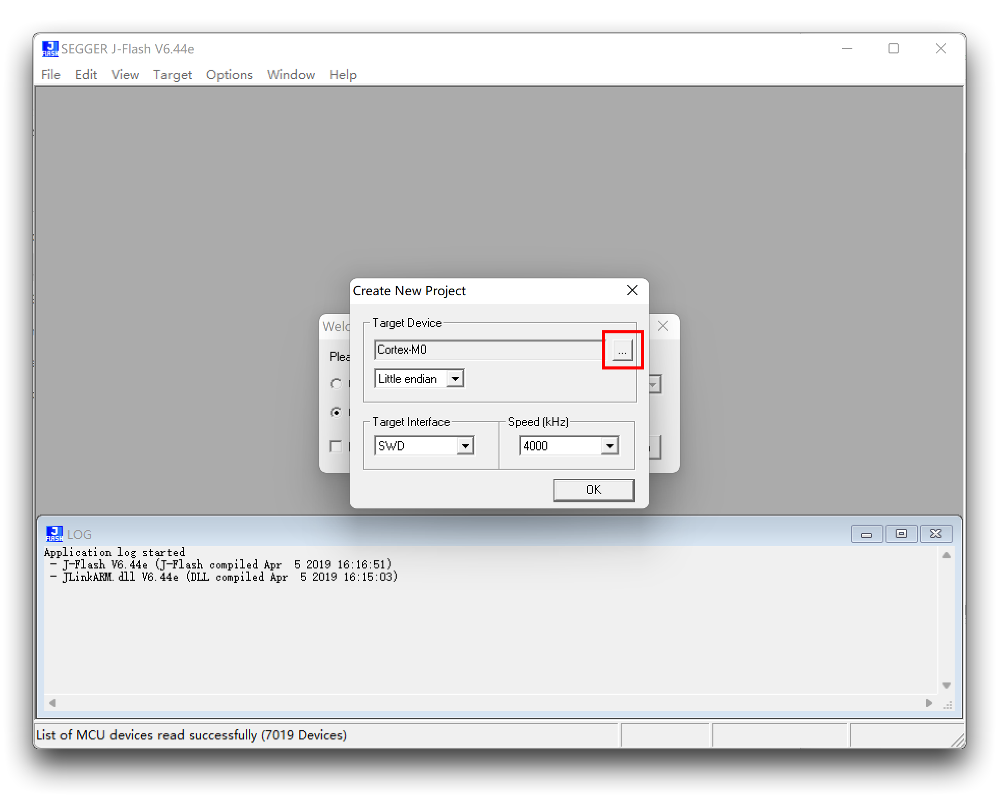
Find and choose AT32F403ARGT7.
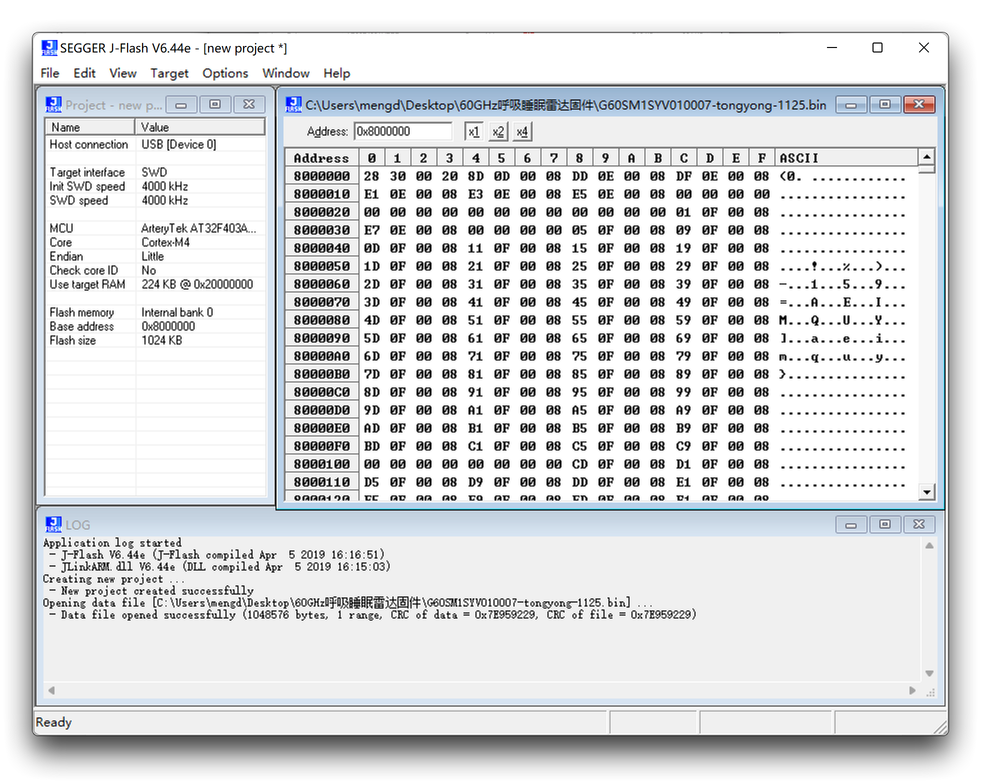
Step 6. Drag and drop the radar firmware (.bin file) into this software and a window will pop up, we will just use its default starting address of 0x8000000.
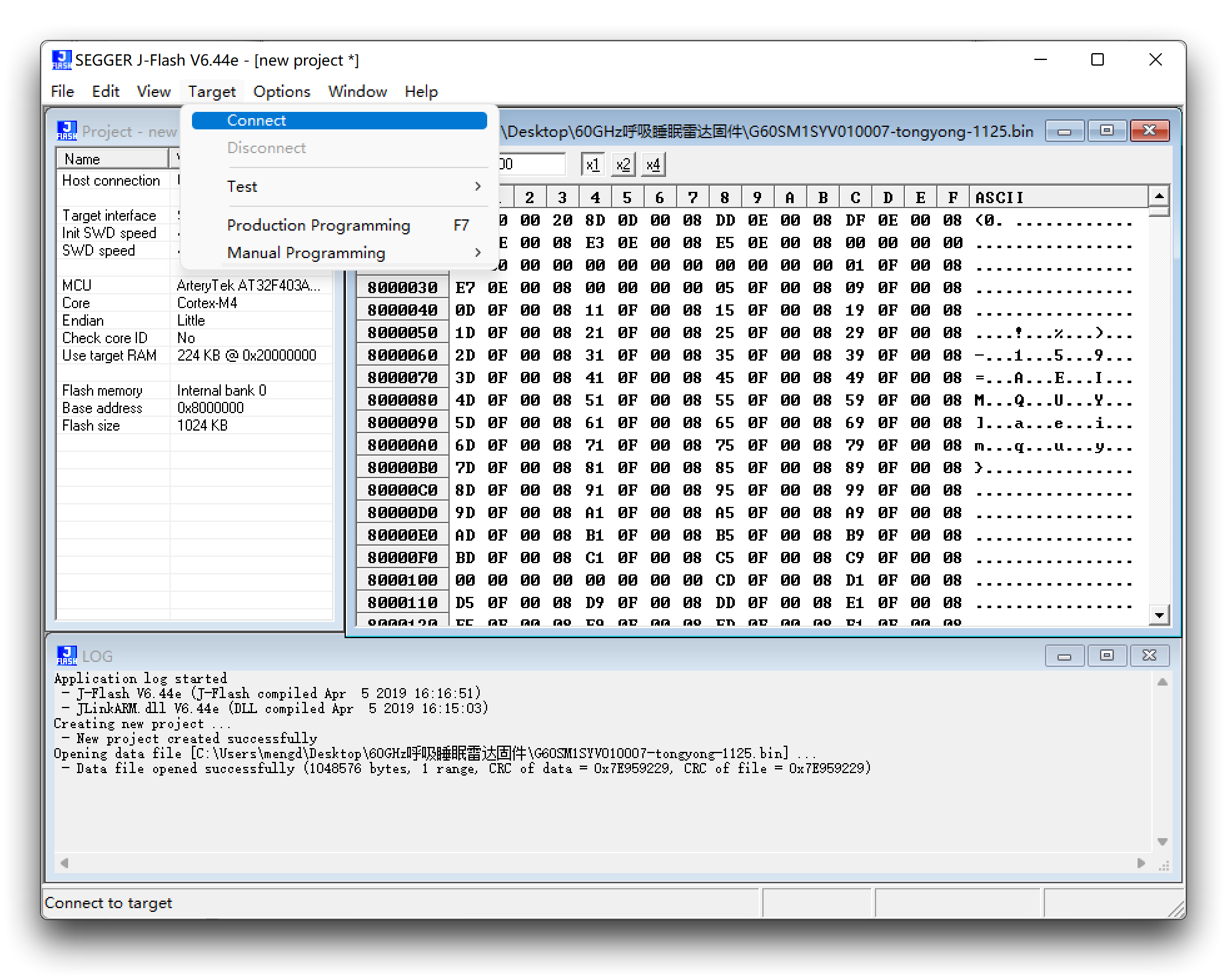
Step 7. Clink Target -> Connect
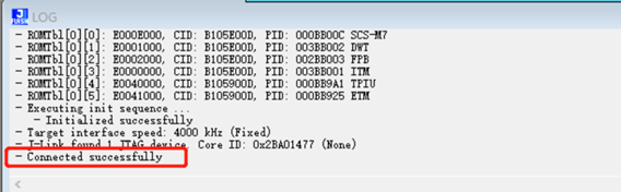
When the connection is successful it will show Connected successfully.
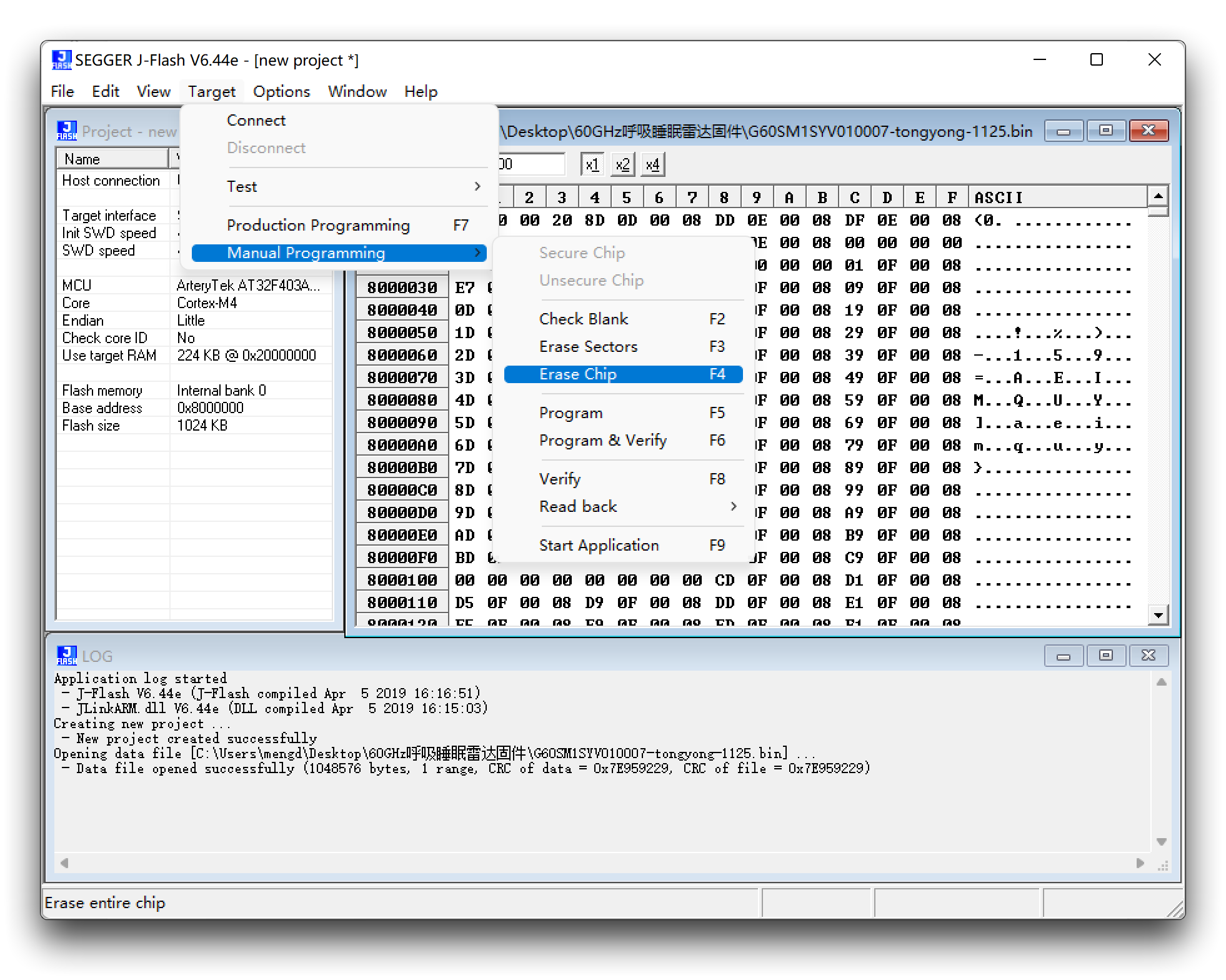
Erase firmware: Target -> manual Programming -> Erase Chip
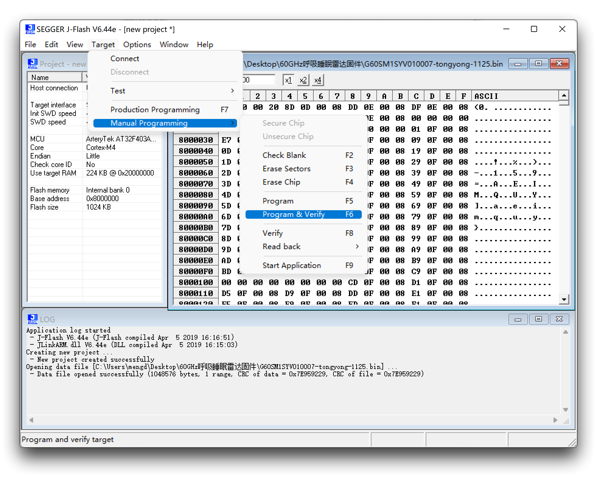
Upgrade firmware: Target -> manual Programming -> Program & Verify
At this point, the firmware update is complete.
Update firmware via UART
Considering that J-link is expensive, it is too extravagant to buy a J-link for the vast majority of users who only need to update their radar firmware, so we offer an update method via UART.
Download of the latest firmware
| Firmware Version | Download Address |
|---|---|
| UART_MR24HPC1-20230302.bin | Download |
-
Please check the function of your product carefully, please do not mix with other mmwave sensors to brush this firmware, otherwise it may cause abnormal product function, the consequences need to be your own responsibility!
-
Please also note that different ways of updating the firmware use different firmware content, what you are downloading is the firmware burned via UART.
-
Make sure your radar firmware version is at least version G24VD1SYV001006 before using the UART to upgrade the firmware, otherwise it may disable the radar, at which point you'll have to use J-link to burn the firmware to use it!
You can query the firmware version number information by sending the command 0x53 0x59 0x02 0xA4 0x00 0x01 0x0F 0x62 0x54 0x43 to Radar. The data reported by the radar is then displayed as a string, and you will see an effect similar to the one shown below.
G24VD1SYV000009 is the model number reported on the radar, where 000009 is the version number. This means that this sensor not supports UART upgrade.

To update your radar to the latest version
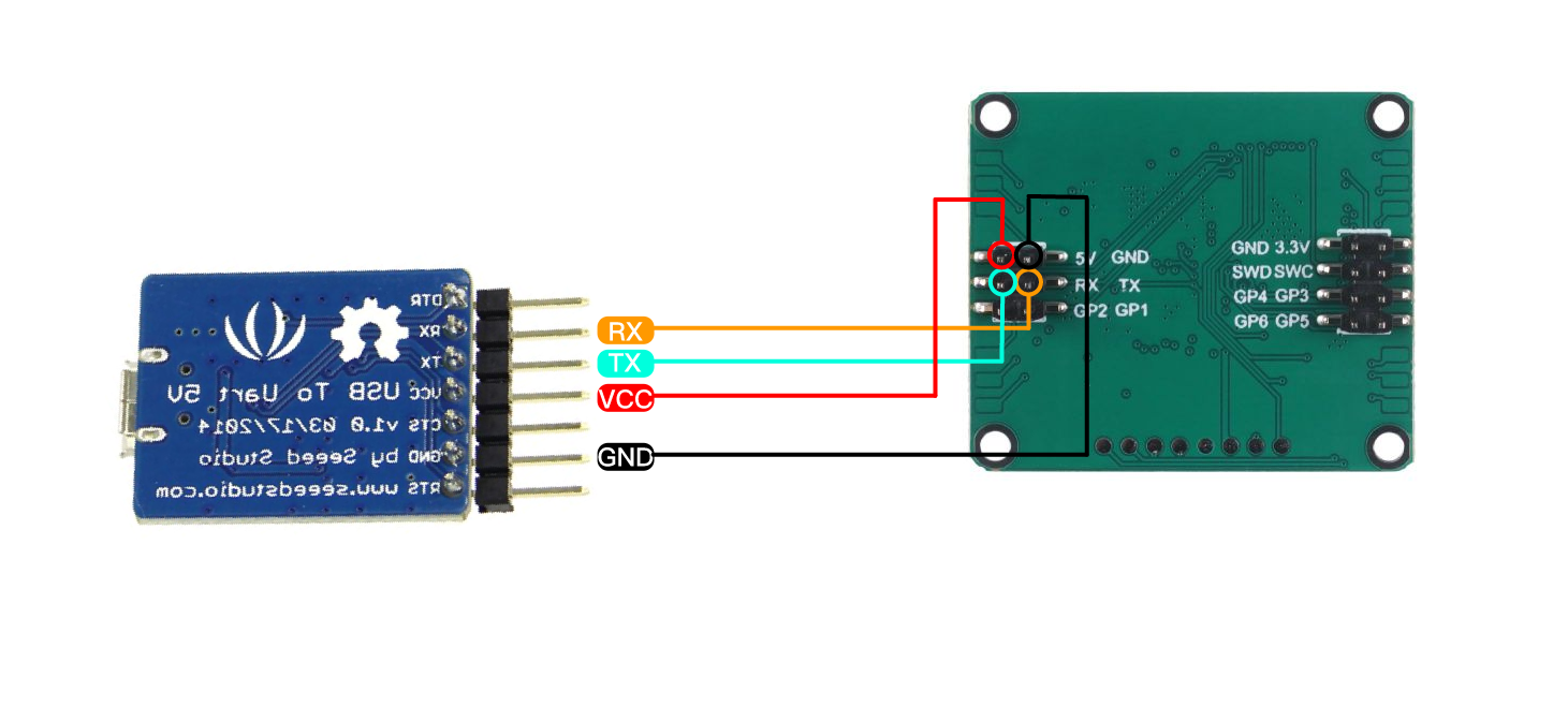
Step 1. You will need to have a UART to USB and MR24HPC1 24GHz mmWave Sensor.
Connect the radar and UART to USB together via Dupont wire as shown in the diagram below.
Step 2. Download the necessary software and firmware.
| File | Download Address |
|---|---|
| PackageMake-v1.1.1.zip | Download |
Step 3. Unzip the package PackageMake-v1.1.1.zip and open the PackageMake-v1.1.1.exe file inside.
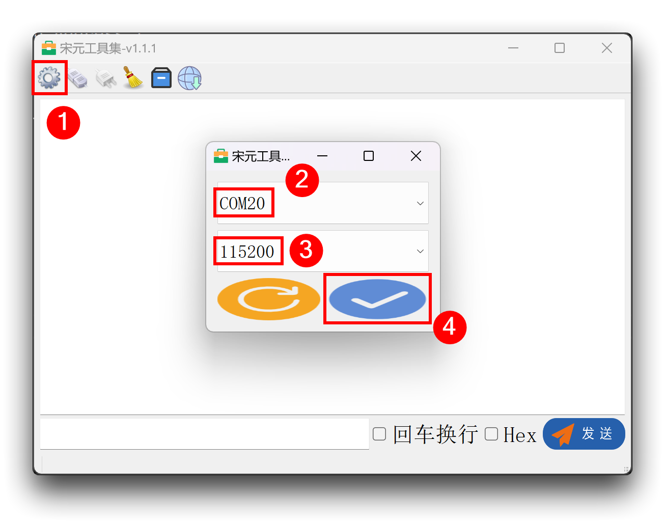
Connect the UART to USB with the sensor connected to the computer, click the gear pattern in the upper left corner of the software, select the port number, set the baud rate to 115200, and then click the bottom right corner to confirm. (If the port number is not found, check the connection and then click the refresh button in the lower left corner to retry)
Step 4. Connecting the sensor
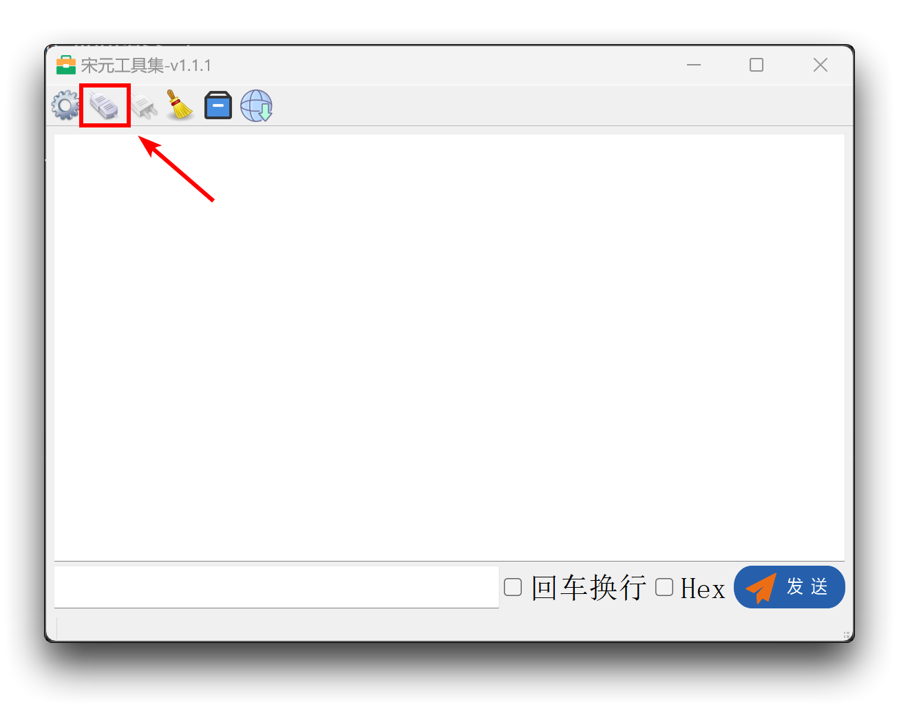
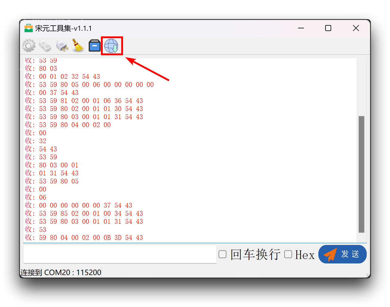
After you have finished setting up the serial port as described above, click on the second icon in the upper right corner and you will see the raw data from the radar printed out if the port is selected correctly.
Step 5. Update firmware
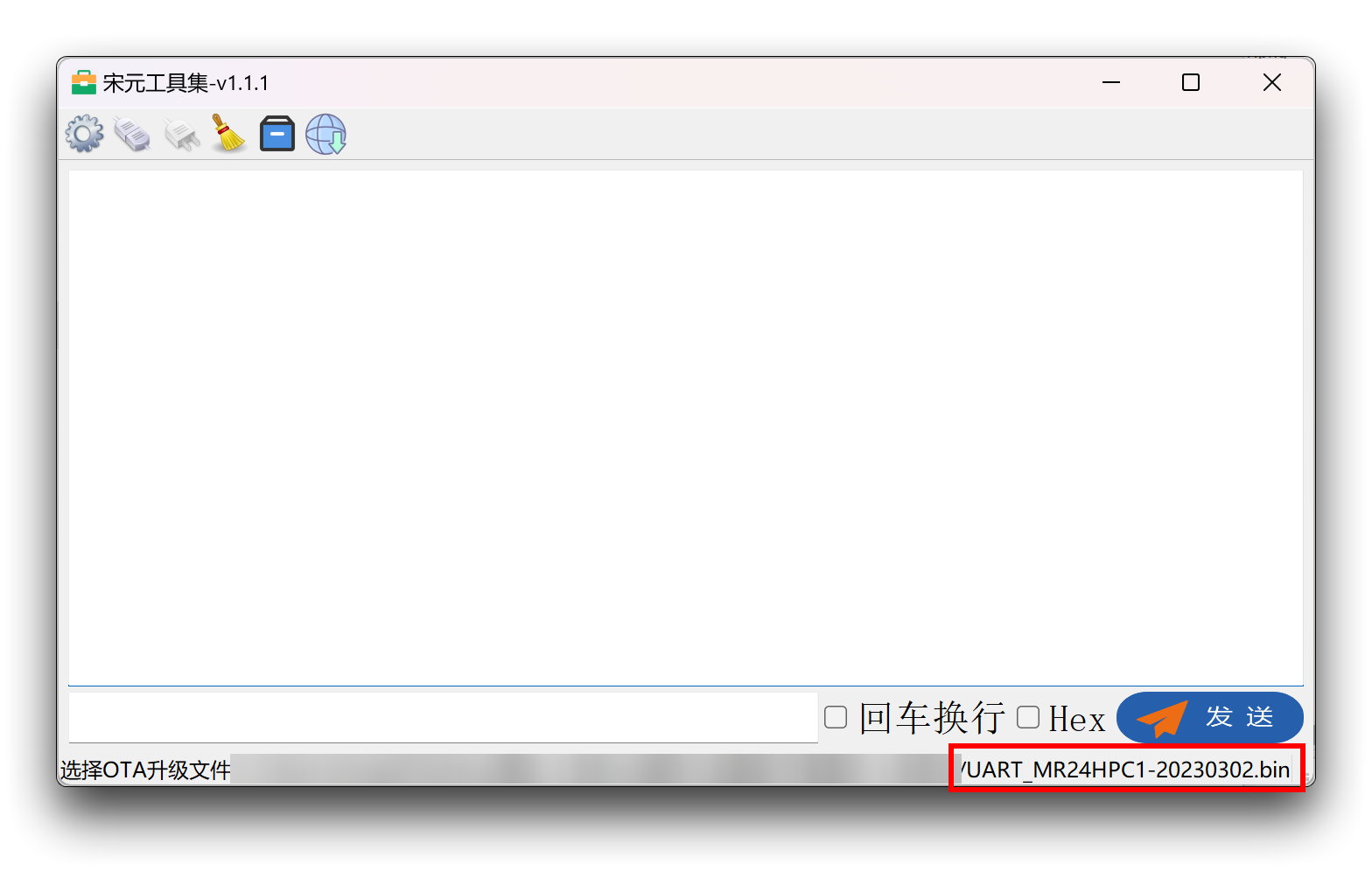
Click the last icon in the upper right corner of the left mouse button, this will bring up a window to select the firmware. Please select the firmware version you have downloaded.
After the selection is complete, the selected file path will appear under the software, please double check if the selected firmware version and model is consistent with the sensor you are using.
To upgrade the firmware, please double click the left mouse button to the last image on the top left of the software, then the firmware will start downloading to the sensor.
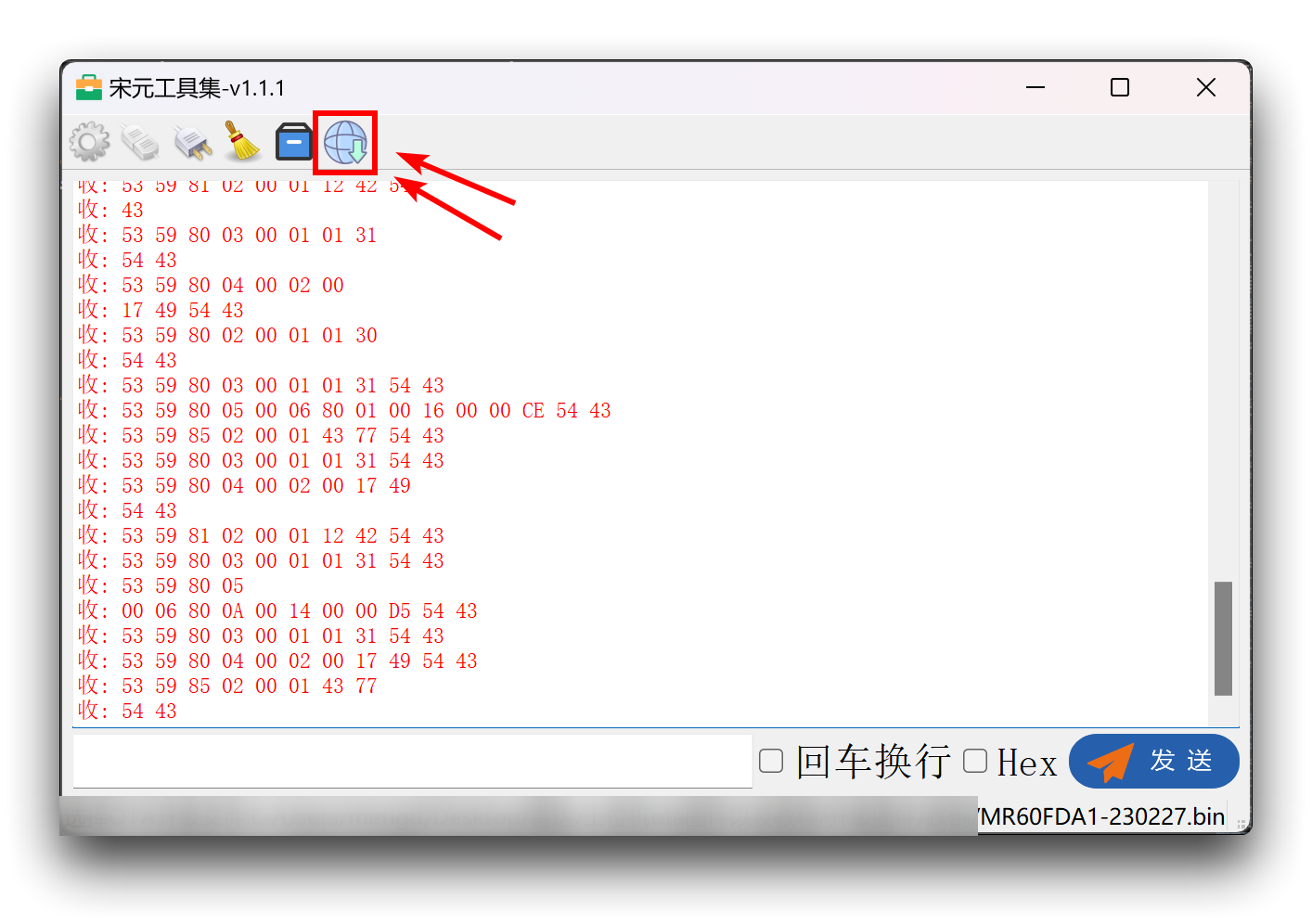
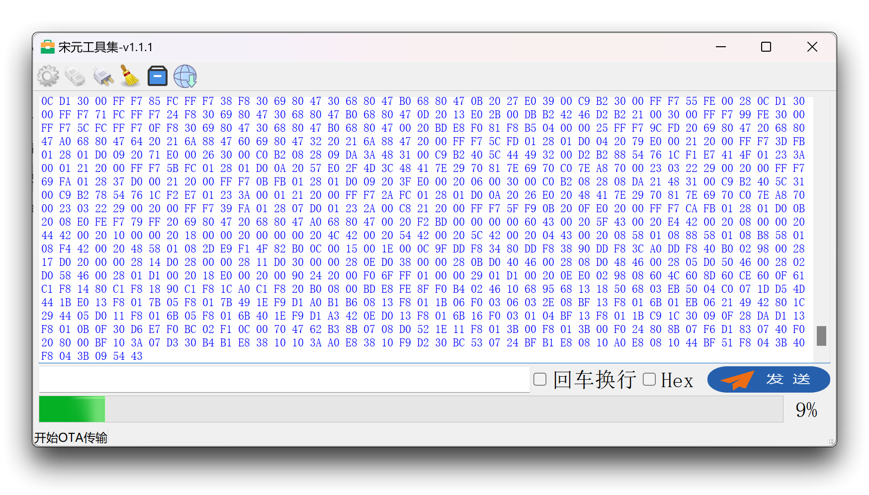
Wait for the progress bar to finish and the firmware update is complete.
Use of the upper computer
Connect the radar directly to the computer's usb port via a UART to USB device. The wiring is shown in the table below.
 | |||
| Radar Sensor | UART to USB | ||
| 5V | --> | 5V | |
| GND | --> | GND | |
| RX | --> | TX | |
| TX | --> | RX | |
In addition to the serial software mentioned above, you can also use the upper computer software designed for radar directly.
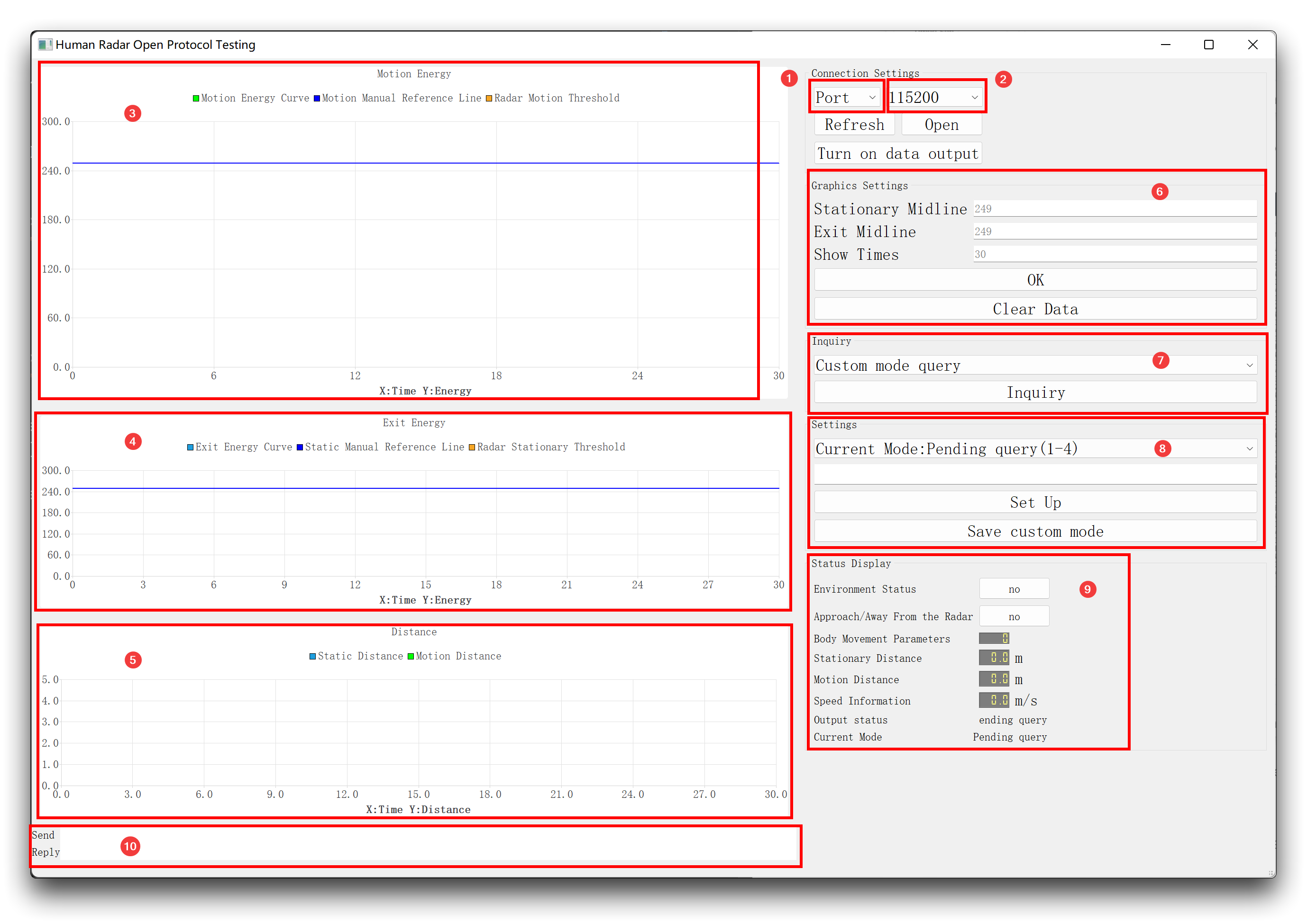
The following ten sections explain the role of each part of the software.
-
Port
Select the port to which the radar is connected to the computer. It is usually necessary to Refresh the port by clicking the Refresh button before selecting it. Once selected please click on the Open button.
-
Baud rate
The MR24HPC1 radar needs to be set at a baud rate of 115200.
-
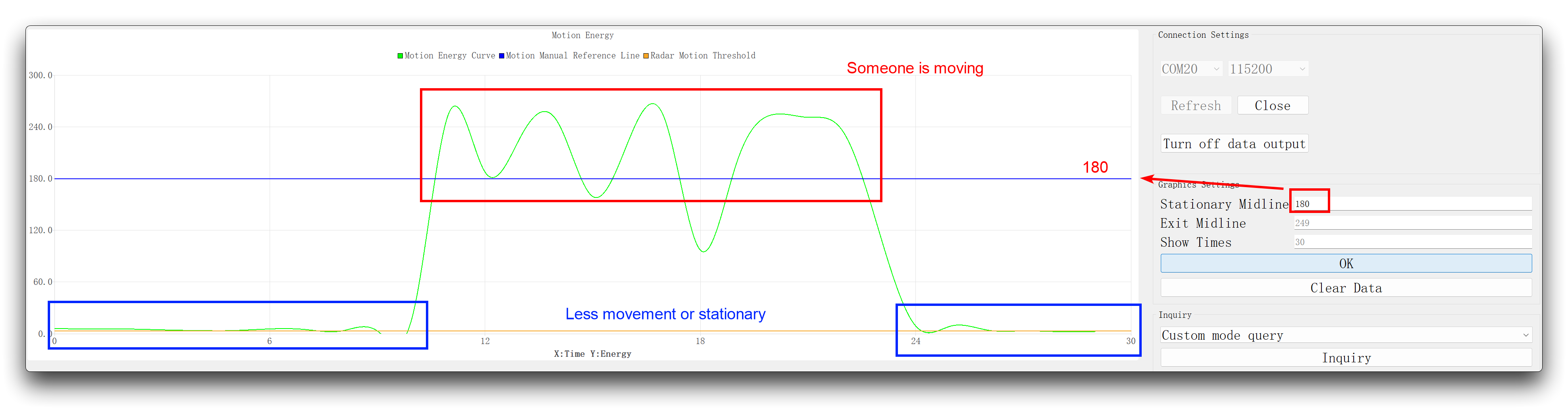
Motion Energy
This value is equivalent to the dynamic value. The variation in this value represents the constant motion noise in the environment. The Motion Energy is low when there is no one in the space, and the overall Motion Energy gets higher as the motion increases in magnitude and distance.
-
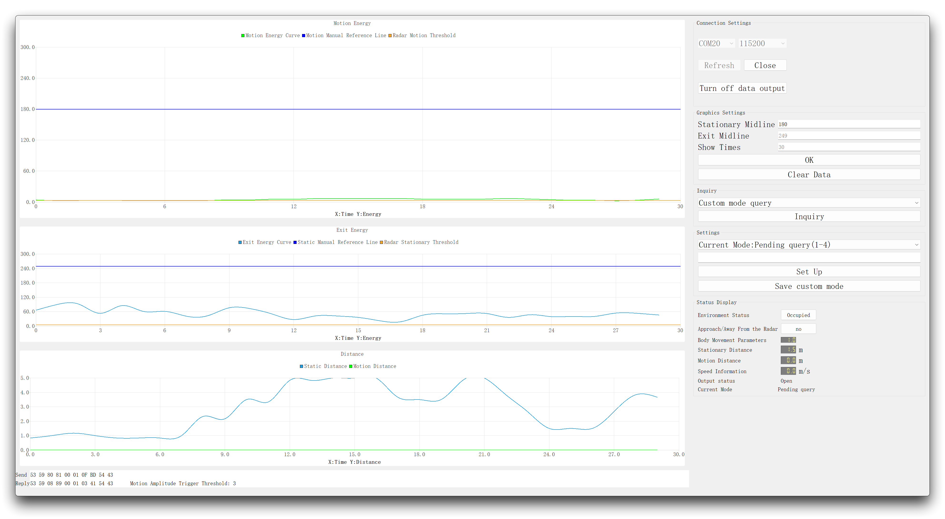
Exit Energy
This value is equivalent to the static value. The variation in this value represents the constant statics noise in the environment. Exit Energy are low when the space is unoccupied, and overall Exit Energy fluctuate at higher values when there is a stationary person in the space (slight movement of the chest breathing).
-
Distance
Stationary distance: The straight line distance between the environment and the radar in the presence of a slightly moving area. When there is someone stationary at a location in space, the straight line distance from the radar is output in real time. Movement distance: The straight-line distance between a moving position in the environment and the radar. When there is a person in motion at a location in space, the straight line distance from the radar is output in real time for that location. the straight-line distance from the radar.
-
Graphics Settings
Used to clearly determine the relationship between real-time waveforms and thresholds relationship. Based on the real time curve changes, it is possible to observe the change in floor noise in different states of the space, and based on the change in floor noise it is possible to set the threshold for the presence of the human body and make a simple judgement of the presence/absence/activity of the stationary state.
-
Inquiry
Search for the current parameter settings. For the meaning of the individual parameter values, please refer to the user manual for details for reasons of space.
-
Settings
Set the threshold values for each parameter.
-
Status Display
This window shows the current distance, speed and movement status in real time, among other values.
-
Send & Reply
The data frames sent and received.
Sensor development with Arduino
Arduino Library Overview
If this is your first time using Arduino, we highly recommend you to refer to Getting Started with Arduino.
The library code used in this example can be downloaded by clicking the icon below.
Function
Before we get started developing a sketch, let's look at the available functions of the library.
-
void recvRadarBytes()—— This function collects the data frames reported by the Sensor via the UART according to the frame headers and frame tails in the Sensor data protocol. Used in conjunction with theshowData()function, the collected data information can be printed out via the serial port.-
Input parameters: None
-
Return value: None
-
-
void showData()—— This function serves to print out the complete data frame reported by the Sensor at once via the serial port and needs to be used in conjunction with therecvRadarBytes()function.-
Input parameters: None
-
Return value: None
-
-
void HumanStatic_func(bool bodysign /*=false*/)—— This function is responsible for parsing the data frames of the Sensor and outputting the relevant data on the state of the human presence.-
Input parameters:
bodysign—— This parameter is a switch that controls whether or not to output Human Movement Parameters. If true, the output will contain a large amount of human sign parameter data, which may affect your experience of viewing the data. By default this parameter is false and no information on the body sign parameters is displayed. -
Return value:
-
int radarStatus—— The value returned indicates which status class the parsed data frame belongs to. The specific categories can be found in the Default Variables section. -
int bodysign_val—— The value returned represents the value of the Human Movement Parameter. This value is only valid with the parameterbodysign=true. -
int static_val—— This value is equivalent to the static value. The variation in this value represents the constant statics noise in the environment. Exit Energy are low when the space is unoccupied, and overall Exit Energy fluctuate at higher values when there is a stationary person in the space (slight movement of the chest breathing). This value is only valid if the Open Underlying Message is on. -
int dynamic_val—— The variation in this value represents the constant motion noise in the environment. The Motion Energy is low when there is no one in the space, and the overall Motion Energy gets higher as the motion increases in magnitude and distance. This value is only valid if the open underlying message is on. -
int dis_static—— The straight line distance between the environment and the Sensor in the presence of a slightly moving area. When there is someone stationary at a location in space, the straight line distance from the Sensor is output in real time. This value is only valid if the Open Underlying Message is on. -
int dis_move—— The straight-line distance between a moving position in the environment and the Sensor. When there is a person in motion at a location in space, the straight line distance from the Sensor is output in real time for that location. the straight-line distance from the Sensor. This value is only valid if the Open Underlying Message is on. -
int speed—— This value indicates the speed of movement of the moving object. The value is for reference only. This value is only valid if the Open Underlying Message is on.
-
-
-
void checkSetMode_func(const unsigned char* buff, int len, bool cyclic /*= false*/)—— This function can be used to send data frames to the Sensor. The data frames sent and the data frames returned are printed out via the serial port.-
Input parameters:
-
buff—— The data frame you want to send to the Sensor. -
len—— The length of the data frame you want to send to the Sensor. -
cyclic—— Cyclic send switch. The default is false, which can be set to true if you wish to send this data frame cyclically.
-
-
Return value: None
-
-
void reset_func()—— The function serves to reset the Sensor.-
Input parameters: None
-
Return value: None
-
Default Variables
#define MESSAGE_HEAD1 0x53       //Data frame header1
#define MESSAGE_HEAD2 0x59       //Data frame header2

#define MESSAGE_END1  0x54       //End1 of data frame
#define MESSAGE_END2  0x43       //End2 of data frame

#define HUMANSTATUS   0x80       //Human Presence Information
#define HUMANEXIST    0x01       //Presence of the human body
#define HUMANMOVE     0x02       //Human movement information
#define HUMANSIGN     0x03       //Body Signs Parameters
#define HUMANDIRECT   0x0B       //Human movement trends

#define SOMEBODY      0x01       //Somebody move
#define NOBODY        0x00       //No one here

#define NONE          0x00
#define SOMEBODY_STOP 0x01       //Somebody stop
#define SOMEBODY_MOVE 0x02       //Somebody move

#define CA_CLOSE      0x01       //Someone approaches
#define CA_AWAY       0x02       //Some people stay away


#define DETAILSTATUS  0x08       //Underlying parameters of the human state
#define DETAILINFO    0x01       //Detailed data on the state of human movement
#define DETAILDIRECT  0x06       //Human movement trends
#define DETAILSIGN    0x07       //Body Signs Parameters

//Return status, Use in arduino
#define SOMEONE       0x01       //There are people
#define NOONE         0x02       //No one
#define NOTHING       0x03       //No message
#define SOMEONE_STOP  0x04       //Somebody stop
#define SOMEONE_MOVE  0x05       //Somebody move
#define HUMANPARA     0x06       //Body Signs Parameters
#define SOMEONE_CLOSE 0x07       //Someone approaches
#define SOMEONE_AWAY  0x08       //Some people stay away
#define DETAILMESSAGE 0x09       //Underlying parameters of the human state

#define reset_frame_len 10       //Reset data frame length

//Reset data frame
const unsigned char reset_frame[10] = {0x53, 0x59, 0x01, 0x02, 0x00, 0x01, 0x0F, 0xBF, 0x54, 0x43};
Installation
Step 1. You need to Install an Arduino Software.

Step 2. Launch the Arduino application.
Step 3. Select your development board model and add it to the Arduino IDE.
-
If you want to use Seeeduino V4.2 for the later routines, please refer to this tutorial to finish adding.
-
If you want to use Seeeduino XIAO for the later routines, please refer to this tutorial to finish adding.
-
If you want to use XIAO RP2040 for the later routines, please refer to this tutorial to finish adding.
-
If you want to use XIAO nRF52840 for the later routines, please refer to this tutorial to finish adding.
-
If you want to use XIAO ESP32C3 for the later routines, please refer to this tutorial to finish adding.
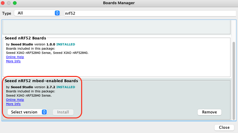
For XIAO nRF52840, please select Seeed nRF52 mbed-enabled Boards, otherwise an error may be reported when running programs.
Step 4. Install the Arduino code library.
Start by getting the code base from GitHub and downloading it to your local computer.
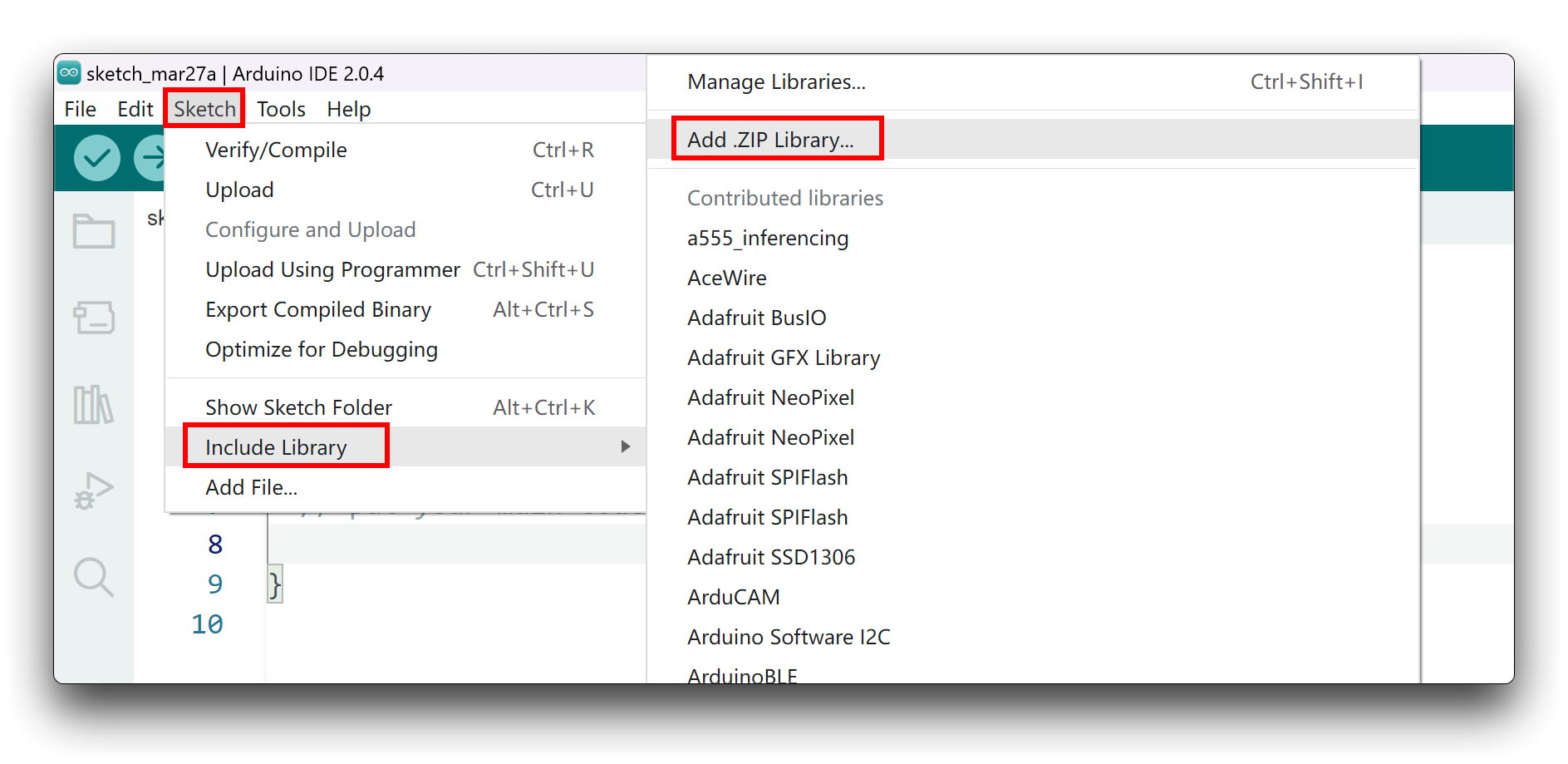
Since you have downloaded the zip Library, open your Arduino IDE, click on Sketch > Include Library > Add .ZIP Library. Choose the zip file you just downloaded,and if the library install correct, you will see Library added to your libraries in the notice window. Which means the library is installed successfully.
Arduino Example
Now that we have our library installed and we understand the basic functions, let's run some examples for our XIAO nRF52840 Sense to see how it behaves.
Materials Required
Before completing the following examples, you will need to prepare the following materials.
|  |  |
| MR24HPC1 | Seeed XIAO BLE nRF52840 Sense | 2mm to 2.54mm Pitch Ribbon Cable |
Step 1. Connect the device to the computer through the main board. The wiring diagram is shown in the table below.
 | |||
| MR24HPC1 | Main Board | ||
| 5V | --> | 5V | |
| GND | --> | GND | |
| RX | --> | D6 | |
| TX | --> | D7 | |
Step 2. In the menu bar in the upper left corner of the Arduino IDE, select tool, choose the type of development board you are using, and select the corresponding serial port.
If you are using MacOS, the serial port name of the device will often start with /dev/cu.usbmodem xxx, ending with the name of the device. If you are using Windows, the device's serial port name will often begin with COM, again ending with the device's name.

In this example, we will demonstrate how the Sensor works with our popular product XIAO nRF52840 Sense.
Demo 1: Serial port printing of raw data frames from Sensor output
This example will guide you through the process of printing out the raw data reported by the Sensor via the serial port.
The following example program is in the examples folder of the library called MR24HPCB1_rawdata_print.
#include "Arduino.h"
#include <humanstaticLite.h>

//#include <SoftwareSerial.h>
// Choose any two pins that can be used with SoftwareSerial to RX & TX
//#define RX_Pin A2
//#define TX_Pin A3

//SoftwareSerial mySerial = SoftwareSerial(RX_Pin, TX_Pin);

// we'll be using software serial
//HumanStaticLite radar = HumanStaticLite(&mySerial);

// can also try hardware serial with
HumanStaticLite radar = HumanStaticLite(&Serial1);

void setup() {
  // put your setup code here, to run once:
  Serial.begin(115200);
  Serial1.begin(115200);

  //  mySerial.begin(115200);

  while(!Serial);   //When the serial port is opened, the program starts to execute.

  Serial.println("Ready");
}

void loop() {
  // put your main code here, to run repeatedly:
  radar.recvRadarBytes();           //Receive radar data and start processing
  radar.showData();                 //Serial port prints a set of received data frames
  delay(200);                       //Add time delay to avoid program jam
}
If you are using XIAO ESP32 series and there is no data feedback from mmwave radar. You can try to change the code above from Serial1.begin(115200); to Serial1.begin(115200, SERIAL_8N1, D7, D6);.
In this program, we are using the XIAO nRF52840's hardware Serial1 port to connect to the Sensor and use the hardware Serial port Serial to output data, so we need to initialise this serial port separately in the initialisation function Setup().
In the main loop() function we use the function recvRadarBytes() to receive data frames from the Sensor and then use the showData() function to print out the received data frames via the serial port.
In this program, it is important to note that there is an interval between the reception and output of every two data frames to avoid a jam on the main board. This time should be no less than 150ms.
This means that there is no way for the main board to receive all the data frames reported by the Sensor, but as the number of frames reported by the Sensor is very large and frequent, this does not affect the accuracy of using the Sensor to determine the environment.
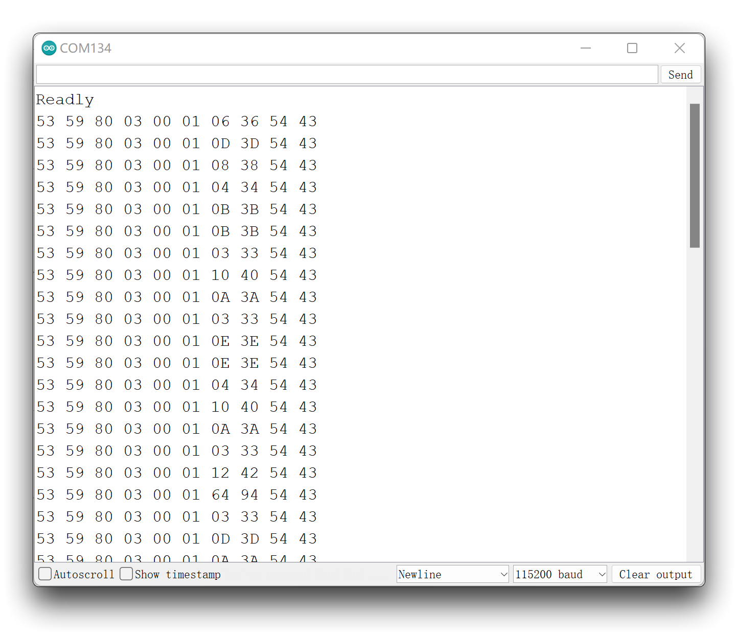
Upload program. Opening your serial monitor to a baud rate of 115200 should show the result. The output should look something like the below image.
Demo 2: Serial port printing of parsed human presence information
In this example, we will use the functions in the library to parse the received data frames and print out all the feature data reported by the Sensor active via the serial port.
The following example program is in the examples folder of the library called MR24HPCB1_parsed_rawdata.
#include "Arduino.h"
#include <humanstaticLite.h>

//#include <SoftwareSerial.h>
// Choose any two pins that can be used with SoftwareSerial to RX & TX
//#define RX_Pin A2
//#define TX_Pin A3

//SoftwareSerial mySerial = SoftwareSerial(RX_Pin, TX_Pin);

// we'll be using software serial
//HumanStaticLite radar = HumanStaticLite(&mySerial);

// can also try hardware serial with
HumanStaticLite radar = HumanStaticLite(&Serial1);

void setup() {
  // put your setup code here, to run once:
  Serial.begin(115200);
  Serial1.begin(115200);

  //  mySerial.begin(115200);

  while(!Serial);   //When the serial port is opened, the program starts to execute.

  Serial.println("Ready");
}

void loop() {
  // put your main code here, to run repeatedly:
  radar.HumanStatic_func(true);    //Turn on printing of human movement sign parameters
  if(radar.radarStatus != 0x00){
    switch(radar.radarStatus){
      Serial.println(radar.radarStatus);
      case SOMEONE:
        Serial.println("Someone is here.");
        Serial.println("---------------------------------");
        break;
      case NOONE:
        Serial.println("Nobody here.");
        Serial.println("---------------------------------");
        break;
      case NOTHING:
        Serial.println("No human activity messages.");
        Serial.println("---------------------------------");
        break;
      case SOMEONE_STOP:
        Serial.println("Someone stop");
        Serial.println("---------------------------------");
        break;
      case SOMEONE_MOVE:
        Serial.println("Someone moving");
        Serial.println("---------------------------------");
        break;
      case HUMANPARA:
        Serial.print("The parameters of human body signs are: ");
        Serial.println(radar.bodysign_val, DEC);
        Serial.println("---------------------------------");
        break;
      case SOMEONE_CLOSE:
        Serial.println("Someone is closing");
        Serial.println("---------------------------------");
        break;
      case SOMEONE_AWAY:
        Serial.println("Someone is staying away");
        Serial.println("---------------------------------");
        break;
      case DETAILMESSAGE:
        Serial.print("Spatial static values: ");
        Serial.println(radar.static_val);
        Serial.print("Distance to stationary object: ");
        Serial.print(radar.dis_static);
        Serial.println(" m");

        Serial.print("Spatial dynamic values: ");
        Serial.println(radar.dynamic_val);

        Serial.print("Distance from the movement object: ");
        Serial.print(radar.dis_move);
        Serial.println(" m");

        Serial.print("Speed of moving object: ");
        Serial.print(radar.speed);
        Serial.println(" m/s");
        Serial.println("---------------------------------");
        break;
    }
  }
  delay(200);
}
If you are using XIAO ESP32 series and there is no data feedback from mmwave radar. You can try to change the code above from Serial1.begin(115200); to Serial1.begin(115200, SERIAL_8N1, D7, D6);.
To implement the data parsing function, we first need to call the HumanStatic_func() function. The parameter passed in can be true or false to control whether the display of the Human Movement Parameters is enabled or not.
If you choose to turn it on, i.e. pass in the parameter true, you may get the following message for the serial port.
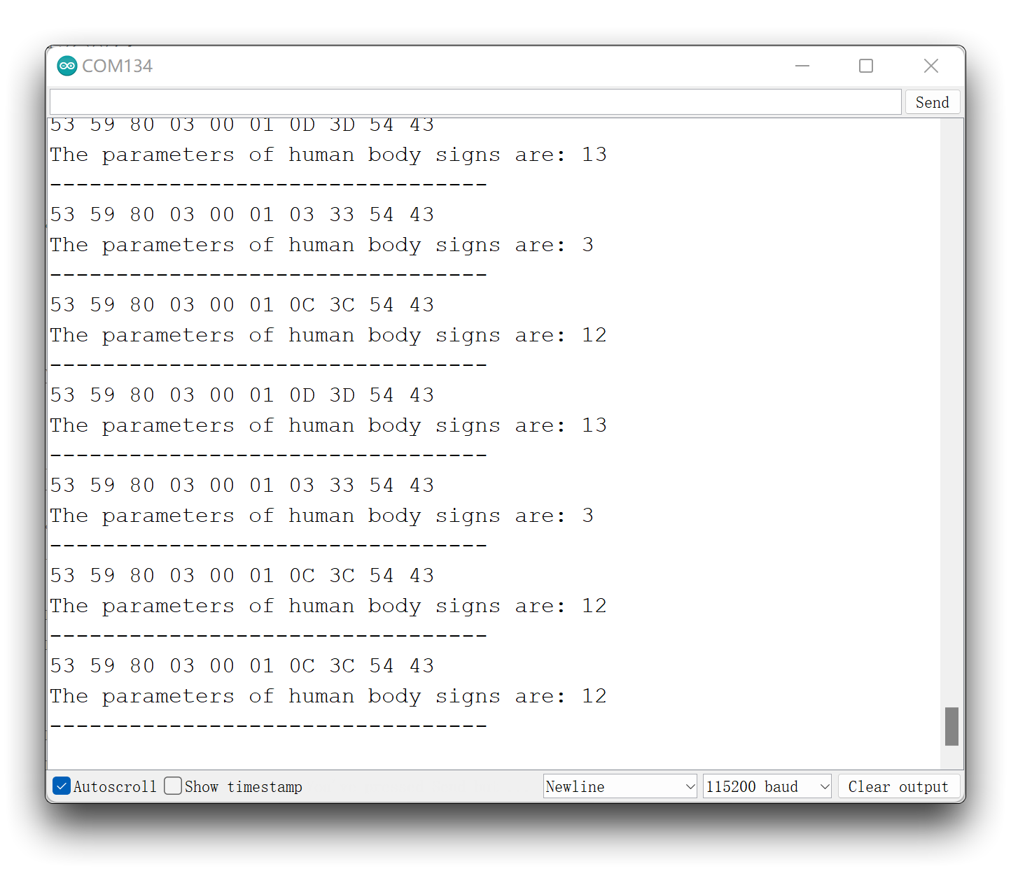
Human Movement Parameters: human movement amplitude values. The Human Movement Parameters is 0 when no one is in the space, 1-5 when someone is present and stationary, and 2-100 when the body is in motion (the greater the motion amplitude the closer the body motion parameter is). This means that if you feel that the results of the Sensor recognition do not meet your expectations, you can output information about the presence of the human body by customising the judgement of the Human Movement Parameters.
If you want to stop the crazy output of the Human Movement Parameters on the serial port, enter the parameter false and you will then be able to see clean body status information on the serial port.
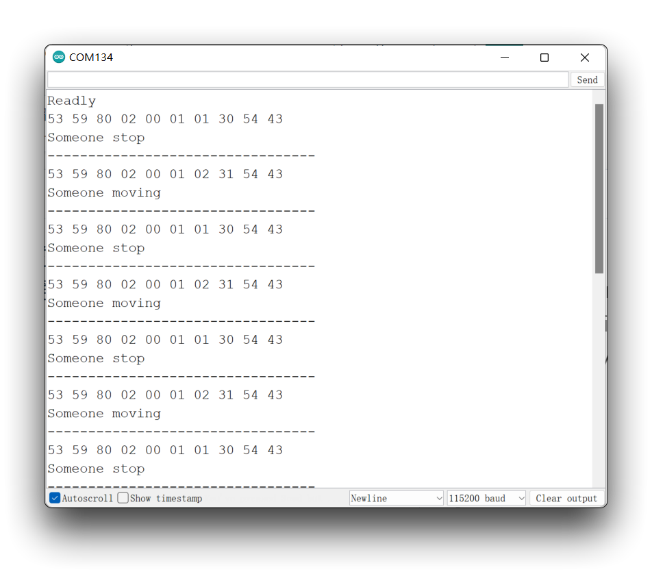
You may not see content printed on the serial monitor for a longer period of time, this may be normal. The algorithm built into the Sensor is such that information is only output when the motion state of the monitored object changes. If you have been stationary after the upload procedure, you may wish to get up and move around and observe the effect.
There is also the possibility that the data you received differs from the information in the data shown in the two images above. Then you may have switched on the Open Underlying Message output switch.
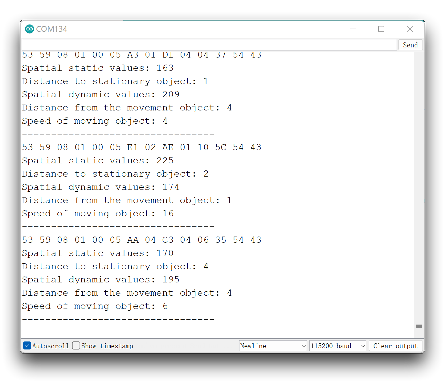
For more information on how to switch on and off Open Underlying Message, please refer to the relevant section of Demo 3. In short, the opening of Open Underlying Message means that more detailed data is exported.
For the meaning of the data of the Open Underlying Message, please consult the Function section or user manual of this Sensor for space reasons.
Demo 3: Send data to Sensor
The MR24HPC1 offers a wealth of mode setting functions. This example will explain the implementation of the switch Open Underlying Message as an example of how to send data frames.
The following example program is in the examples folder of the library called MR24HPCB1_open_underlyingMes.
#include "Arduino.h"
#include <humanstaticLite.h>

//#include <SoftwareSerial.h>
// Choose any two pins that can be used with SoftwareSerial to RX & TX
//#define RX_Pin A2
//#define TX_Pin A3

//SoftwareSerial mySerial = SoftwareSerial(RX_Pin, TX_Pin);

// we'll be using software serial
//HumanStaticLite radar = HumanStaticLite(&mySerial);

// can also try hardware serial with
HumanStaticLite radar = HumanStaticLite(&Serial1);

const unsigned char close_buff[10] = {0x53, 0x59, 0x08, 0x00, 0x00, 0x01, 0x00, 0xB5, 0x54, 0x43};  //switch off Open Underlying Message
const unsigned char open_buff[10] = {0x53, 0x59, 0x08, 0x00, 0x00, 0x01, 0x01, 0xB6, 0x54, 0x43};   //switch on Open Underlying Message

void setup() {
  // put your setup code here, to run once:
  Serial.begin(115200);
  Serial1.begin(115200);

  //  mySerial.begin(115200);

  while(!Serial);   //When the serial port is opened, the program starts to execute.

  Serial.println("Ready");
}

void loop() {
  // put your main code here, to run repeatedly:
  radar.checkSetMode_func(open_buff, 10, false);
  delay(50);   //Do not set the delay time too long, as this may affect the reception of the data frames returned by the radar.
}
If you are using XIAO ESP32 series and there is no data feedback from mmwave radar. You can try to change the code above from Serial1.begin(115200); to Serial1.begin(115200, SERIAL_8N1, D7, D6);.
Before sending data to the Sensor, we need to consult the user manual to obtain the complete data frames to be sent according to our needs and define an array in the program to hold the data frames to be sent.
In this example, we have created two arrays of data frames according to the user manual. Their function is to turn on or off the Open Underlying Message function.
const unsigned char close_buff[10] = {0x53, 0x59, 0x08, 0x00, 0x00, 0x01, 0x00, 0xB5, 0x54, 0x43};  //switch off Open Underlying Message
const unsigned char open_buff[10] = {0x53, 0x59, 0x08, 0x00, 0x00, 0x01, 0x01, 0xB6, 0x54, 0x43};   //switch on Open Underlying Message
Regarding the calculation of the check digit "sum".
All data frames have a checksum bit to ensure that the data is sent or received accurately. The checksum bit is usually in the penultimate bit of the data frame. It is calculated by adding up all the bits preceding the check bit and taking the lower two bits in hexadecimal. Let's take the example of a data frame that queries the device ID.

It can be seen that the checksum bit is in the penultimate bit of the entire data frame. Then we start by adding all the previous hexadecimal numbers.
0x53 + 0x59 + 0x02 + 0xA2 + 0x00 + 0x01 + 0x0F = 0x0160
Then we need to take the lower two digits of it, which would be 60, so the checksum of this data frame is 60. If we want to look up the ID of the Sensor, then you can define the following array.
const unsigned char DevID_buff[10] = {0x53, 0x59, 0x02, 0xA1, 0x00, 0x01, 0x0F, 0x60, 0x54, 0x43};
Then we send the data frame by calling the checkSetMode_func() function. The parameters passed in are an array of data frames, the length of the array and a boolean value for whether to send it cyclically.
radar.checkSetMode_func(open_buff, 10, false);
Upload program. Opening your serial monitor to a baud rate of 115200 should show the result. The output should look something like the below image.
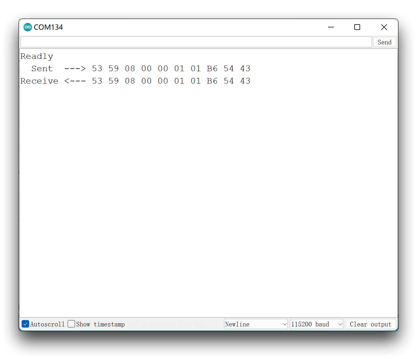
At this point please check the data frames returned and if they match the data frames returned as described in the user manual, then the setup was successful.
Normally, our commands do not need to be repeated to the Sensor, but as the Sensor replies with messages so fast that we cannot be sure that we will receive the exact data message returned by the Sensor. There are two solutions to this problem.
- Re-upload the above procedure several times.
- Set the third parameter of the
checkSetMode_func()function (cyclic sending) totrue. Please note, however, that repeatedly sending data frames of the setting type may cause the Sensor to jam, so please use this function with caution. If the Sensor is stuck, disconnect the 5V supply pin from the Sensor and wait a few moments for the function to resume.
Demo 4: Reset Sensor
There may be times when you have problems with your Sensor detecting anomalies or when you want to clear all settings on your Sensor, then you can reset your Sensor according to this example.
The following example program is in the examples folder of the library called MR24HPCB1_reset_radar.
#include "Arduino.h"
#include <humanstaticLite.h>

//#include <SoftwareSerial.h>
// Choose any two pins that can be used with SoftwareSerial to RX & TX
//#define RX_Pin A2
//#define TX_Pin A3

//SoftwareSerial mySerial = SoftwareSerial(RX_Pin, TX_Pin);

// we'll be using software serial
//HumanStaticLite radar = HumanStaticLite(&mySerial);

// can also try hardware serial with
HumanStaticLite radar = HumanStaticLite(&Serial1);

void setup() {
  // put your setup code here, to run once:
  Serial.begin(115200);
  Serial1.begin(115200);

  //  mySerial.begin(115200);

  while(!Serial);   //When the serial port is opened, the program starts to execute.

  Serial.println("Ready");

  radar.reset_func();
}

void loop() {
  // put your main code here, to run repeatedly:

}
If you are using XIAO ESP32 series and there is no data feedback from mmwave radar. You can try to change the code above from Serial1.begin(115200); to Serial1.begin(115200, SERIAL_8N1, D7, D6);.
Resetting the Sensor is very simple, you just need to call reset_func(). The reset only needs to be executed once, so we use it in the Setup() function.
Demo 5: Using Arduino/Seeeduino
Our library is Arduino compatible and you can also choose the Arduino you have on hand to develop your Sensor project.
The MR24HPC1 Sensor communicates using the UART serial port, you just need to connect the Sensor to your Arduino as wired below.
| MR24HPC1 | MCU | |
| 5V | --> | 5V |
| GND | --> | GND |
| RX | --> | soft serial port TX |
| TX | --> | soft serial port RX |
All the functions are applied in the same way as in Demo 1 to Demo 4 above, so we will not repeat them in this example. In this example, we will give you an overview of how to use the Arduino's soft serial port to get data information from the Sensor.
For notes on the Arduino soft serial port, please refer to the official Arduino documentation.
To avoid data confusion caused by using Serial for both output and data transmission, on the Arduino side we usually use a soft serial port.
The import of the soft serial port library and the definition of the RX and TX pins need to be done earlier in the program. The following program defines the A2 and A3 pins as the RX and TX pins of the soft serial port.
#include <SoftwareSerial.h>
//Choose any two pins that can be used with SoftwareSerial to RX & TX
#define RX_Pin A2
#define TX_Pin A3

SoftwareSerial mySerial = SoftwareSerial(RX_Pin, TX_Pin);

//we'll be using software serial
HumanStaticLite radar = HumanStaticLite(&mySerial);
Also, don't forget to set the baud rate for the soft serial port in the Setup() function.
void setup() {
  // put your setup code here, to run once:
  Serial.begin(115200);

  mySerial.begin(115200);

  while(!Serial);   //When the serial port is opened, the program starts to execute.

  Serial.println("Ready");
}
Using Demo 1 as an example, if you want to use the Arduino to print the reported data frames from the Sensor, then the complete program is as follows.
#include "Arduino.h"
#include <humanstaticLite.h>

#include <SoftwareSerial.h>
// Choose any two pins that can be used with SoftwareSerial to RX & TX
#define RX_Pin A2
#define TX_Pin A3

SoftwareSerial mySerial = SoftwareSerial(RX_Pin, TX_Pin);

// we'll be using software serial
HumanStaticLite radar = HumanStaticLite(&mySerial);

void setup() {
  // put your setup code here, to run once:
  Serial.begin(115200);

  mySerial.begin(115200);

  while(!Serial);   //When the serial port is opened, the program starts to execute.

  Serial.println("Ready");
}

void loop() {
  // put your main code here, to run repeatedly:
  radar.recvRadarBytes();           //Receive radar data and start processing
  radar.showData();                 //Serial port prints a set of received data frames
  delay(200);                       //Add time delay to avoid program jam
}
Demo 6: Direct connection to PC for data
You can refer to this routine if you want to use an upper computer designed for Sensor, or if you want to use the serial software to get a complete data frame.
Connect the Sensor directly to the computer's usb port via a UART to USB device. The wiring is shown in the table below.
| |||
| Radar Sensor | UART to USB | ||
| 5V | --> | 5V | |
| GND | --> | GND | |
| RX | --> | TX | |
| TX | --> | RX | |
Use a software like serial debugging assistant to select the serial port where the Sensor is located.
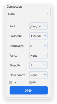
MR24HPC1 Sensor needs 5V power supply, otherwise the Sensor may not work properly.
After a successful connection, you will see the Sensor sending a steady stream of messages.
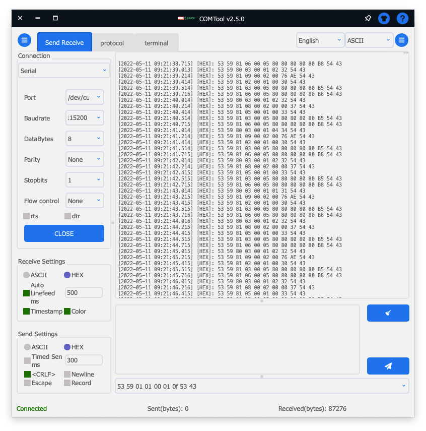
At the same time, you can also send data frames to the Sensor via the software's send function.
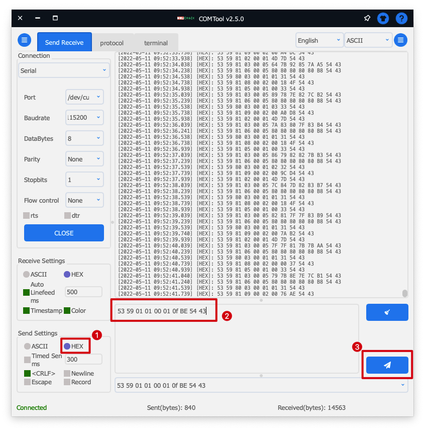
Demo 7: MR24HPBC1 & XIAO ESP32C3 & ESPHome & Home Assistant
We have created a tutorial for connecting to ESPHome and Home Assistant for this radar and the XIAO ESP32C3, if you are interested, you can refer to the tutorial here.
Demo 8: Using sensors in the XIAO ESP32C3
Due to the special design of the XIAO ESP32C3 hardware serial port, you will need to use the following code in order to use the UART to send and receive data messages with the sensor.
#include "Arduino.h"
#include <humanstaticLite.h>
#include <HardwareSerial.h>

//HardwareSerial MySerial(0); // If you want to use D6 and D7 as serial pins, uncomment this line and comment the following line instead.
HardwareSerial MySerial(1);   // Create a new HardwareSerial class

// can also try hardware serial with
HumanStaticLite radar = HumanStaticLite(&MySerial);

void setup() {
  // put your setup code here, to run once:
  Serial.begin(115200);

  /*
   * 4, 5 indicate GPIO4 and GPIO5, corresponding to pins D2 and D3.
   * If you want to use the hardware UART pins of the XIAO ESP32C3 directly, you can change 4, 5 to -1, -1.
   * MySerial.begin(115200, SERIAL_8N1, -1, -1);
   *
   * In addition to this you can also use the D9 (GPIO9) and D10 (GPIO10) pins as serial ports.
   * MySerial1.begin(115200, SERIAL_8N1, 9, 10);
   */
  MySerial.begin(115200, SERIAL_8N1, 4, 5);

  while(!Serial);   //When the serial port is opened, the program starts to execute.

  delay(500);

  Serial.println("Ready");
}

void loop() {
  // put your main code here, to run repeatedly:
  radar.recvRadarBytes();           //Receive radar data and start processing
  radar.showData();                 //Serial port prints a set of received data frames
  delay(200);                       //Add time delay to avoid program jam
}
Troubleshooting
FAQ 1: Can this Sensor detect more than one person at a time in the same environment?
A: Not available. This Sensor can only be used on a single living object. If more than one person or animal is in the monitoring range, this will have an effect on the results of the monitoring.
FAQ 2: Why can't I see anything in the serial monitor with the XIAO ESP32C3?
XIAO ESP32C3 serial port function is not quite consistent with the general Arduino hardware, and using Serial1 directly may cause the USB serial port not to work. For related application cases, please go to the Serial chapter of XIAO ESP32C3 for details.
FAQ 3: Is is avaliable to use other chip instead of XIAO ESP32-C3 to use the library?
Yes, it is indeed possible to use other chips instead of XIAO ESP32-C3 with the library. Just make sure you connect the correct RX/TX pins or two GPIO pins and set the baud rate to 115200.
Confirm which method to use, software or hardware, for example if you have an Arduino Uno R3 which has only one serial port, you can implement as below:
#include "Arduino.h"
#include <humanstaticLite.h>

#include <SoftwareSerial.h>
// Choose any two pins that can be used with SoftwareSerial to RX & TX
#define RX_Pin A2
#define TX_Pin A3

SoftwareSerial mySerial = SoftwareSerial(RX_Pin, TX_Pin);

// we'll be using software serial
HumanStaticLite radar = HumanStaticLite(&mySerial);

void setup() {
  // put your setup code here, to run once:
  Serial.begin(115200);
  mySerial.begin(115200);
}
void loop() {
  // Your code here
}
Resources
- [PDF] Quick Setup Template
- [PDF] Datasheet
- [PDF] User Manual
- [EXE] upper computer software
- [ZIP] CE certification documents
Tech Support & Product Discussion
Thank you for choosing our products! We are here to provide you with different support to ensure that your experience with our products is as smooth as possible. We offer several communication channels to cater to different preferences and needs.