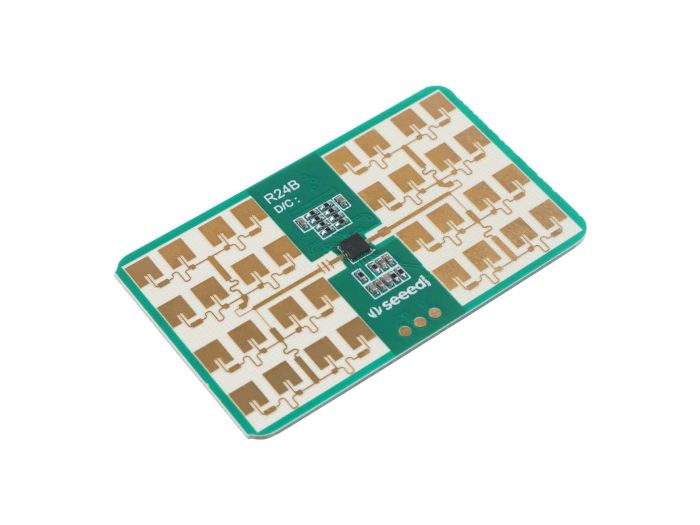
24GHz mmWave Sensor - Sleep Breathing Monitoring (MR24BSD1)
Introduction
The MR24BSD1 24GHz radar module applies Dopplor detected theory to implement human sleep quality monitoring providing a fully total private and secure sensing environment, independently from other noisy influences. It is a useful privacy-protected, secure sensor radar systems in smart home applications like sleep safety alarm, sleep respiratory detection.
Application
- Smart Home
- Smart Hotel
- Human Sleep Quailty Monitor
Feature
- Enabled theory: Implement detection based on 24GHz mmWave Doppler radar technology
- Vital signs detection: Sense simultaneously moving and stationary persons, detect respiratory sleep to monitor human sleep quality
- Perfect privacy protection: Apply mmWave monitoring technology to provide surveillance capabilities without identification
- Health-friendly working status: Output power as low as harmless to human body
- High stability: Independ from temperature, humidity, noise, airflow, dust, light and other environmental influences
- High flexibility radar: Support secondary development and adapt to various scenarios applications
Specification
| Operating parameters | Minimum value | Typical values | Maximum value | Unit |
|---|---|---|---|---|
| Operating voltage (VCC) | 4.5 | 5.0 | 6 | V |
| Operating current (ICC) | 90 | 93 | 100 | mA |
| Operating I/O Inflow/Output Current (IIO) | - | 8 | 20 | mA |
| Operating temperature (TOP) | -20 | - | +60 | ℃ |
| Storage temperature (TST) | -40 | - | +80 | ℃ |
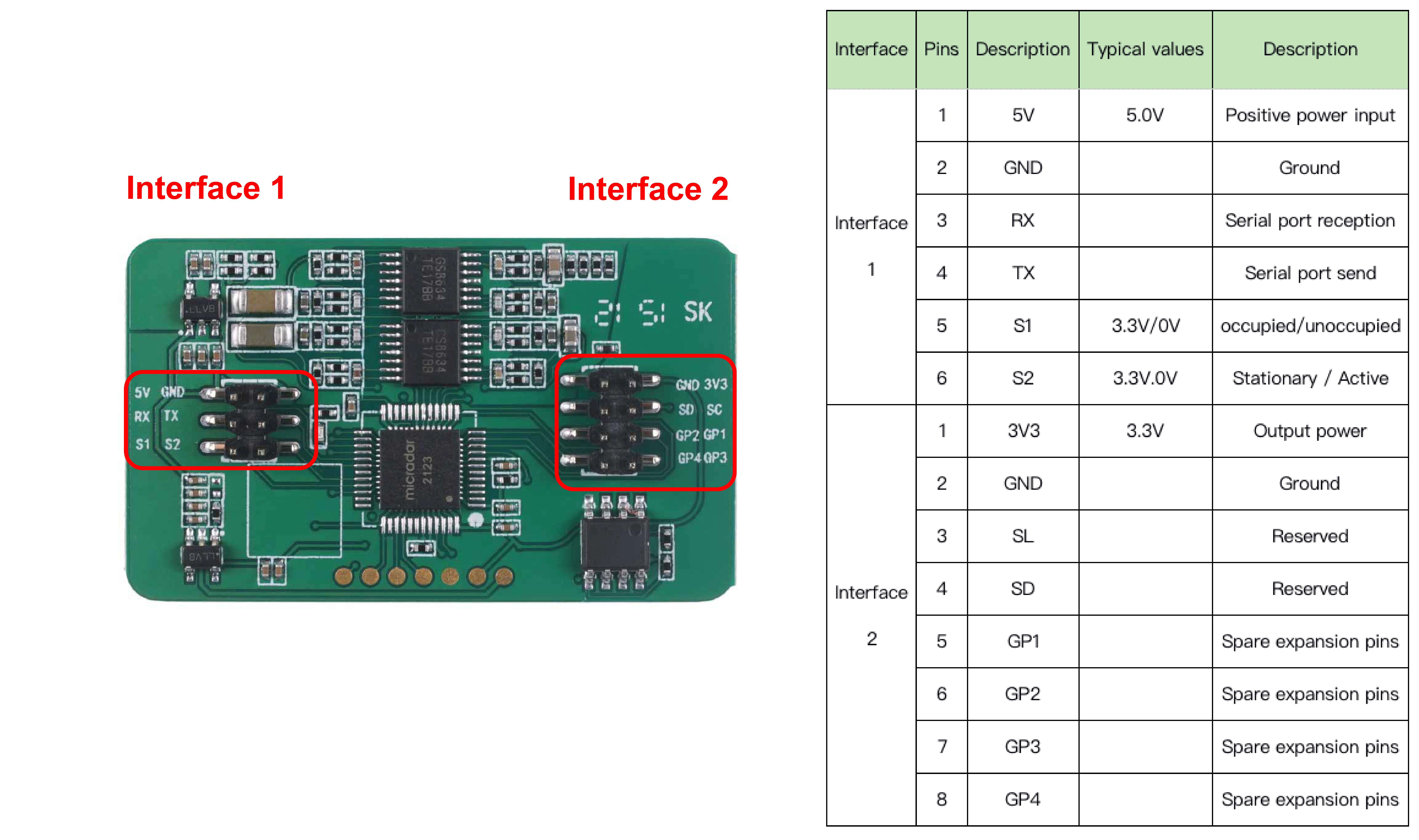
Hardware Overview
Before everything starts, it is quite essential to have some basic parameters of the product. The following table provides information about the characteristics of Sleep Breathing Monitoring Radar.
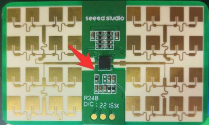
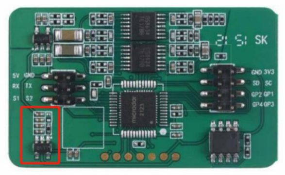
We have some updates about the hardware.
- There is an resistor used for filtering RC. Since it doesn't use in the module as we tested, it has been removed.
2.Since we removed the LED from the module, the resistor here limited cicuit has been canceled as well.
Getting Started
Arduino Library Overview
If this is your first time using Arduino, we highly recommend you to refer to Getting Started with Arduino.
The library code used in this example can be downloaded by clicking the icon below.
Function
Before we get started developing a sketch, let's look at the available functions of the library.
-
void recvRadarBytes()—— This function takes the length of the current frame returned by radar. The frames are stored in an array according to that length. Input parameters: None Return value: None -
void Bodysign_judgment(byte inf[], float Move_min, float Move_max)—— The data returned by the radar contains a large amount of physical data. The user has the flexibility to adjust the detected motion information based on the sign data and the decoding algorithm provided by the function. The content of the judgment will be output via the serial port. Input parameters:-
byte inf[]—— Data frames sent by the radar. -
float Move_min—— Determine the threshold of the user being in a stationary or unoccupied state. -
float Move_max—— Determine the threshold value for the user to be in a stationary state or a state where someone is in motion.Return value: None About the description of the sign parameters: Theoretically, the calculated values of the sign parameters range from 0 to 100. When the calculated value is 0, it means that no one is detected in the surrounding environment. When the calculated value is 1, it means that the environment is detected to be occupied and in a stationary state. A calculated value of 2 to 100 indicates that the surroundings are detected to be occupied and active.
-
-
void Situation_judgment(byte inf[])—— This function detects whether the human body is approaching or moving away from the location where the radar is located and determines the movement of the human body, according to the algorithm inside the radar. This information will be output through the serial port. Input parameters:-
byte inf[]—— Data frames sent by the radar.Return value: None
-
-
void Sleep_inf(byte inf[])—— This function completes the decoding of the sleep information returned by the radar and prints the results of the radar detection through the serial port. Sleep information includes: breathing rate, breathing conditions, scene judgment, sleep conditions and quality, and sleep duration, etc. Input parameters:-
byte inf[]—— Data frames sent by the radar.Return value: None
-
-
unsigned short int us_CalculateCrc16(unsigned char *lpuc_Frame, unsigned short int lus_Len)—— This function is used to generate CRC16 checksum. Input parameters:-
unsigned char *lpuc_Frame—— The data frame you want to send to the radar (not including the final 2 Byte checksum frame). -
unsigned short int lus_Len—— The length of the data frame you want to send to the radar.Return value: 2 Byte integer type check digit.
-
-
void SleepTimeCalculate(unsigned char sleeptime[])—— This function is used to parse the data frames returned by the radar into sleep time. The sleep time is printed out through the serial port. Input parameters:-
unsigned char sleeptime[]—— The 4 Byte sleep duration data returned by the radar.Return value: None
-
-
void SerialInit()—— Set the radar serial port baud rate to 9600. If it is a Seeeduino board, set the soft serial port to RX: 2, TX: 3. Input parameters: None Return value: None
Default Variables
#define MESSAGE_HEAD 0x55       //Data frame header
#define ACTIVE_REPORT 0x04      //Proactive reporting

#define REPORT_RADAR 0x03       //Report radar information
#define REPORT_OTHER 0x05       //Report other information

#define HEARTBEAT 0x01          //Heartbeat Pack
#define ABNOEMAL 0x02           //Abnormal Reset
#define ENVIRONMENT 0x05        //Environment
#define BODYSIGN 0x06           //Physical parameters
#define CLOSE_AWAY 0x07         //Approach away

#define CA_BE 0x01              //Approach away head frame
#define CA_CLOSE 0x02           //Someone approaches
#define CA_AWAY 0x03            //Some people stay away
#define SOMEBODY_BE 0x01        //Motion state header frame
#define SOMEBODY_MOVE 0x01      //Somebody move
#define SOMEBODY_STOP 0x00      //Somebody stop
#define NOBODY 0x00             //No one here

#define SLEEP_INF 0x05          //Sleep radar data header frames
#define BREATH 0x01             //Breathing parameters
#define SCENARIO 0x03           //Scenario evaluation
#define SLEEP_TIME 0x04         //Duration parameters
#define SLEEP_QUALITY 0x05      //Sleep quality

#define BREATH_RATE 0x01        //Breathing rate
#define CHECK_SIGN 0x04         //Detection signal

#define BREATH_HOLD 0x01        //Breath-holding abnormalities
#define BREATH_NULL 0x02        //None
#define BREATH_NORMAL 0x03      //Normal breathing
#define BREATH_MOVE 0x04        //Movement abnormalities
#define BREATH_RAPID 0x05       //Acute respiratory abnormalities

#define CLOSE_AWAY_BED 0x07     //Getting in and out of bed judgment
#define SLEEP_STATE 0x08        //Sleep state judgment

#define AWAY_BED 0x00           //Leaving the bed
#define CLOSE_BED 0x01          //Get into bed

#define AWAKE 0x00              //sleep state:Awake
#define LIGHT_SLEEP 0x01        //sleep state:Light sleep
#define DEEP_SLEEP 0x02         //sleep state:deep sleep
#define SLEEP_NULL 0x03         //no sleep state

#define AWAKE_TIME 0x01         //Awake time
#define LIGHT_SLEEP_TIME 0x02   //Light sleep time
#define DEEP_SLEEP_TIME 0x03    //Deep sleep time

#define SLEEP_SCORE 0x01        //Sleep quality score

const byte MsgLen = 12;         //Data frame maximum length value
byte dataLen = 12;              //Real data frame length
byte Msg[12];                   //Set a fixed array to receive the first data
boolean newData = false;        //Controlling the reception of a new set of data
Installation
Step 1. You need to Install an Arduino Software.

Step 2. Launch the Arduino application.
Step 3. Select your development board model and add it to the Arduino IDE.
-
If you want to use Seeeduino V4.2 for the later routines, please refer to this tutorial to finish adding.
-
If you want to use Seeeduino XIAO for the later routines, please refer to this tutorial to finish adding.
-
If you want to use XIAO RP2040 for the later routines, please refer to this tutorial to finish adding.
-
If you want to use XIAO BLE for the later routines, please refer to this tutorial to finish adding.
Step 4. Install the Arduino code library.
Start by getting the code base from GitHub and downloading it to your local computer.
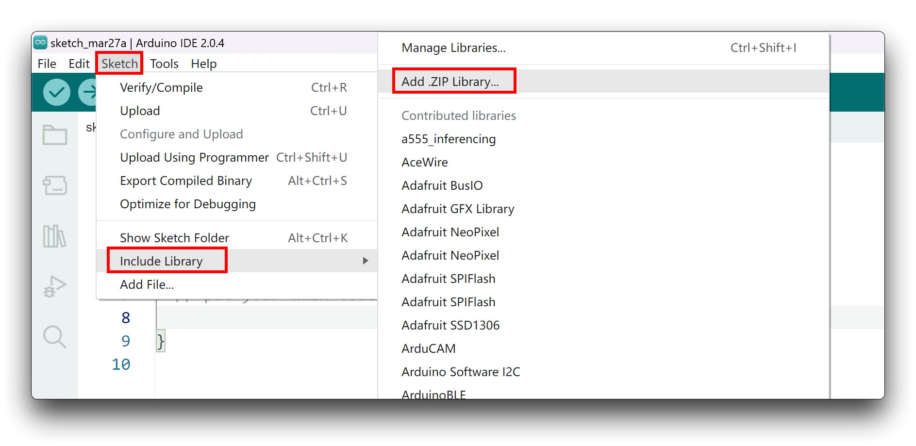
Since you have downloaded the zip Library, open your Arduino IDE, click on Sketch > Include Library > Add .ZIP Library. Choose the zip file you just downloaded,and if the library install correct, you will see Library added to your libraries in the notice window. Which means the library is installed successfully.
Arduino Example
Now that we have our library installed and we understand the basic functions, let's run some examples for our XIAO BLE to see how it behaves.
Materials Required
Before completing the following examples, you will need to prepare the following materials.
|  |  |
| 24GHz mmWave Radar Sensor | Seeed XIAO BLE nRF52840 Sense | 2mm to 2.54mm Pitch Ribbon Cable |
Step 1. Connect the device to the computer through the main board. The wiring diagram is shown in the table below.
 | |||
| Radar Sensor | Main Board | ||
| 5V | --> | 5V | |
| GND | --> | GND | |
| RX | --> | D6 | |
| TX | --> | D7 | |
Step 2. In the menu bar in the upper left corner of the Arduino IDE, select tool, choose the type of development board you are using, and select the corresponding serial port.
If you are using MacOS, the serial port name of the device will often start with /dev/cu.usbmodem xxx, ending with the name of the device. If you are using Windows, the device's serial port name will often begin with COM, again ending with the device's name.

In this example, we will demonstrate how the radar works with our popular product XIAO BLE.
Demo1 Decode built-in radar algorithm data output environment status
The radar has a complete set of built-in algorithms that can directly output the environmental conditions obtained by the radar judgment. This routine will describe how to print out the environmental conditions detected by the radar directly through the serial port via code.
The code in this example is as follows.
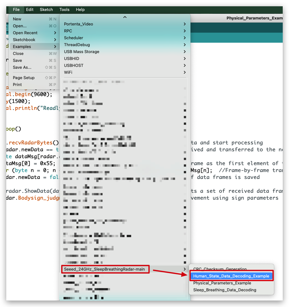
//Human_State_Data_Decoding_Example.ino

#include <sleepbreathingradar.h>

SleepBreathingRadar radar;

void setup()
{
  radar.SerialInit();
  Serial.begin(9600);
  delay(1500);
  Serial.println("Readly");
}

void loop()
{
 radar.recvRadarBytes();                       //Receive radar data and start processing
 if (radar.newData == true) {                  //The data is received and transferred to the new list dataMsg[]
    byte dataMsg[radar.dataLen+1] = {0x00};
    dataMsg[0] = 0x55;                         //Add the header frame as the first element of the array
    for (byte n = 0; n < radar.dataLen; n++)dataMsg[n+1] = radar.Msg[n];  //Frame-by-frame transfer
    radar.newData = false;                     //A complete set of data frames is saved

    //radar.ShowData(dataMsg);                 //Serial port prints a set of received data frames
    radar.Situation_judgment(dataMsg);         //Use radar built-in algorithm to output human motion status
  }
}
In the setup() code, we turn on the Serial port and the Serial1 port on the XIAO BLE. Serial is used for data printing and Serial1 is used for communication between the XIAO BLE and the radar. According to the baud rate of the radar, we set the baud rate of both serial ports to 9600. When it is ready, the serial monitor will print Ready.
radar.recvRadarBytes();
if (radar.newData == true) {
    byte dataMsg[radar.dataLen+1] = {0x00};
    dataMsg[0] = 0x55;
    frame as the first element of the array
    for (byte n = 0; n < radar.dataLen; n++)dataMsg[n+1] = radar.Msg[n];
    radar.newData = false;
}
In the loop, we first use the recvRadarBytes() function to store the data sent by the radar in a fixed-length array Msg[12]. Due to the complexity of radar data, a single fixed-length array is not sufficient for our data processing task, so we need an array that can be resized to store the set of data according to the current data frame length. This is where the array dataMsg[dataLen] comes into play, seeing that dataLen is the actual length of the current data frame.
radar.Situation_judgment(dataMsg);
When the dataMsg list is completely obtained, it will be used as the parameter of the Situation_judgment() function to complete the output of environmental monitoring data, and the output result will be printed directly on the serial monitor.
Upload program. Opening your serial monitor to a baud rate of 9600 should show the result. The output should look something like the below image.
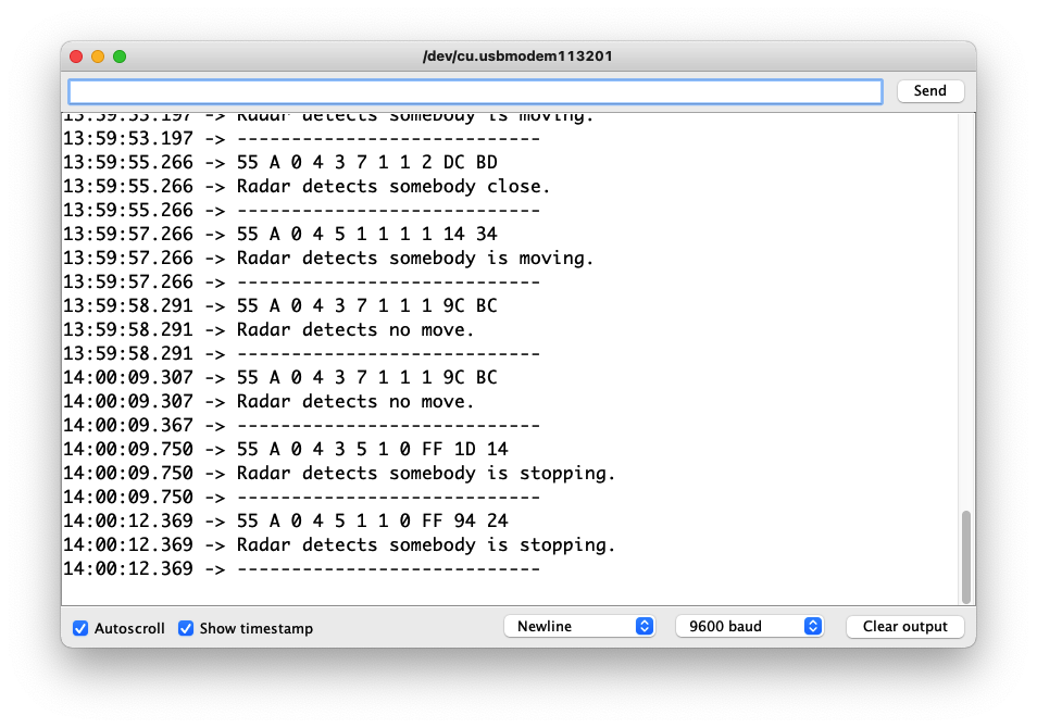
If you do not see data after opening the serial monitor it may be normal. The acquisition of this part of the radar data depends on the changes in human movement within the radar monitoring range. Only when the movement of the person within range changes, the radar will send data, and only then will the data be printed out.
If you want to see what data is returned by radar, you can uncomment radar.ShowData(dataMsg);, which will output the complete set of received data frames through the serial monitor.
Demo2 Obtaining human motion using feature parameter analysis
Among the large amount of data returned by radar, information on physical data makes up the majority of the information. Sometimes, over-reliance on the radar's own algorithms can yield less than satisfactory results in some scenarios. Then, we can choose to use the information returned by the radar to make suitable adjustments according to the actual application scenarios.
The code in this example is as follows.

//Physical_Parameters_Example.ino

#include <sleepbreathingradar.h>

SleepBreathingRadar radar;

void setup()
{
  radar.SerialInit();
  Serial.begin(9600);
  delay(1500);
  Serial.println("Readly");
}

void loop()
{
 radar.recvRadarBytes();                       //Receive radar data and start processing
 if (radar.newData == true) {                  //The data is received and transferred to the new list dataMsg[]
    byte dataMsg[radar.dataLen+1] = {0x00};
    dataMsg[0] = 0x55;                         //Add the header frame as the first element of the array
    for (byte n = 0; n < radar.dataLen; n++)dataMsg[n+1] = radar.Msg[n];  //Frame-by-frame transfer
    radar.newData = false;                     //A complete set of data frames is saved

    //radar.ShowData(dataMsg);                 //Serial port prints a set of received data frames
    radar.Bodysign_judgment(dataMsg, 1, 15); //Output of human movement using sign parameters
  }
}
radar.Bodysign_judgment(dataMsg, 1, 15);
Once the dataMsg array is obtained, we can pass the data of this array as the first argument to the Bodysign_judgment() function, which parses the sign parameters.
The second and third parameters of the function Bodysign_judgment() are the critical values for judging the unoccupied and the human body at rest, the critical values for the human body at rest and in motion, respectively.
(1, 15) means that when the calculated value of the body sign is less than 1, output no one is in the environment. When the somatic value is greater than or equal to 1 and less than 15, the output is that the current environment is occupied by someone in a stationary state. When the value of body sign is greater than or equal to 35, it outputs that there is someone moving in the environment.
Upload program. Opening your serial monitor to a baud rate of 9600 should show the result. The output should look something like the below image.
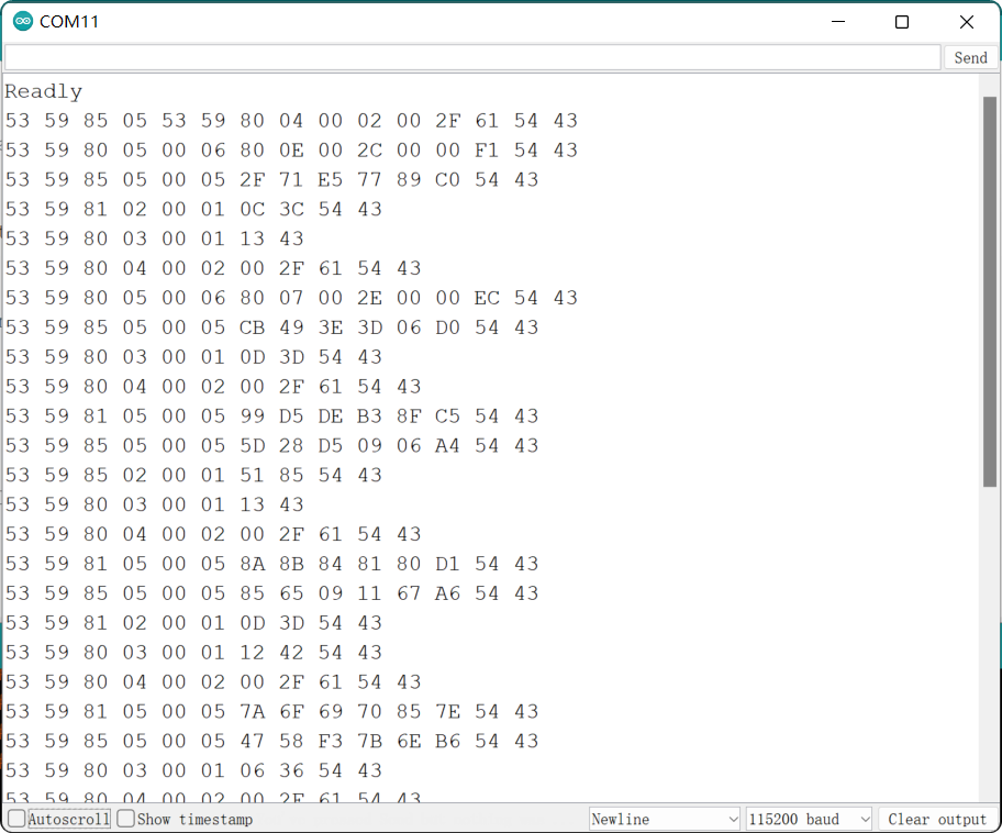
The values following the output data frame represent the calculated sign values.
Demo 3 Get sleep detection data
Sleep detection as a special function of 24GHz breathing sleep radar, we can complete the output of detection data by the following code example.
The code in this example is as follows.
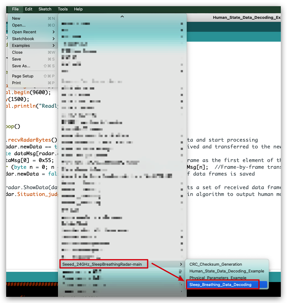
//Sleep_Breathing_Data_Decoding.ino

#include <sleepbreathingradar.h>

SleepBreathingRadar radar;

void setup()
{
  radar.SerialInit();
  Serial.begin(9600);
  delay(1500);
  Serial.println("Readly");
}

void loop()
{
 radar.recvRadarBytes();                       //Receive radar data and start processing
 if (radar.newData == true) {                  //The data is received and transferred to the new list dataMsg[]
    byte dataMsg[radar.dataLen+1] = {0x00};
    dataMsg[0] = 0x55;                         //Add the header frame as the first element of the array
    for (byte n = 0; n < radar.dataLen; n++)dataMsg[n+1] = radar.Msg[n];  //Frame-by-frame transfer
    radar.newData = false;                     //A complete set of data frames is saved

    //radar.ShowData(dataMsg);                 //Serial port prints a set of received data frames
    radar.Sleep_inf(dataMsg);                  //Sleep information output
  }
}
radar.Sleep_inf(dataMsg);
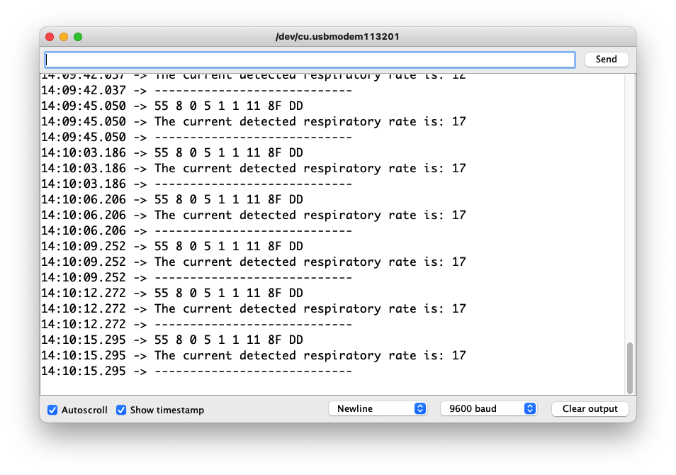
When the dataMsg list is completely obtained, it will be used as the parameter of the Sleep_inf() function to complete the output of sleep monitoring data, and the output result will be printed directly on the serial monitor.
Upload program. Opening your serial monitor to a baud rate of 9600 should show the result. The output should look something like the below image.
Demo 4 Sending data to radar
Radar opens a very large number of interfaces for us to get information and to set the radar sensitivity or scene. This routine will instruct the user how to use the user manual to send data messages to the radar to adjust the parameters of the radar or to obtain the desired data information.
Step 1. Obtain data frames based on the desired query.
Download the user manual in the Resource area, and in Chapter 8.2, find the content of the frames you need to query or set up, and organize them.
In this example, assuming you want to look up the ID of the radar device, you should be able to get the desired function code, address code 1 and address code 2.

Step 2. Open the sample code in Arduino IDE.

The code in this example is as follows.
//CRC_Checksum_Generation.ino

#include <sleepbreathingradar.h>

SleepBreathingRadar radar;
char buff[30];

void setup()
{
  radar.SerialInit();
  Serial.begin(9600);
  delay(1500);
  Serial.println("Readly");
}

void loop()
{
  //Please fill in the data frame you want to set according to the datasheet(Excluding 2 Byte checksum frames)
  unsigned char data[] = {0x55, 0x08, 0x00, 0x05, 0x01, 0x04, 0x03};

  unsigned int length = sizeof(data)/sizeof(unsigned char);
  unsigned char datas[length + 2];
  for (int n = 0; n < length; n++)datas[n] = data[n];
  unsigned short int crc_data = radar.us_CalculateCrc16(data, length);
  sprintf(buff, "The CRC16 values is: %04x", crc_data);
  Serial.println(buff);
  datas[length] = (crc_data & 0xff00) >> 8;
  datas[length+1] = crc_data & 0xff;
  Serial.print("The datas send to the radar: ");
  for (int n = 0; n < length + 2; n++){
    char buffsend[1];
    sprintf(buffsend, "0x%02x ", datas[n]);
    Serial.print(buffsend);
  }
  Serial.println();
  delay(6000);
}
Step 3. Modifies the content of the data frame to generate the complete data frame sent to the radar.
What we need to modify is the data[] array in the loop.
//Please fill in the data frame you want to set according to the datasheet(Excluding 2 Byte checksum frames)
unsigned char data[] = {0x55, 0x08, 0x00, 0x05, 0x01, 0x04, 0x03};
The places we need to modify are the second element, the fourth to the last element. The header frame 0x55 is fixed and does not need to be modified. The second frame is the length frame, please modify it according to the length of the data you send. The third frame is fixed to 0x00. The fourth frame is the function code, the fifth frame is the address code 1, and so on.
About the length frame calculation method:
Length = Data Length + Function Code + Address Code 1 + Address Code 2 + Data + Checksum. (Head frames are not counted)
See Chapter 8 of the user manual for more information on frame formats and rules.
Upload program. Opening your serial monitor to a baud rate of 9600 should show the result. The output should look something like the below image.

The complete data that needs to be sent to the radar will be displayed in the serial monitor.
Other ways
If you don't want to use any master to generate complete data frames, you can also paste this code below into an editor that can run C programs. Follow the above procedure and fill in the array data with the contents of your frames.
#include <stdio.h>

const unsigned char cuc_CRCHi[256]= {
  0x00, 0xC1, 0x81, 0x40, 0x01, 0xC0, 0x80, 0x41, 0x01, 0xC0, 0x80, 0x41,
  0x00, 0xC1, 0x81, 0x40, 0x01, 0xC0, 0x80, 0x41, 0x00, 0xC1, 0x81, 0x40,
  0x00, 0xC1, 0x81, 0x40, 0x01, 0xC0, 0x80, 0x41, 0x01, 0xC0, 0x80, 0x41,
  0x00, 0xC1, 0x81, 0x40, 0x00, 0xC1, 0x81, 0x40, 0x01, 0xC0, 0x80, 0x41,
  0x00, 0xC1, 0x81, 0x40, 0x01, 0xC0, 0x80, 0x41, 0x01, 0xC0, 0x80, 0x41,
  0x00, 0xC1, 0x81, 0x40, 0x01, 0xC0, 0x80, 0x41, 0x00, 0xC1, 0x81, 0x40,
  0x00, 0xC1, 0x81, 0x40, 0x01, 0xC0, 0x80, 0x41, 0x00, 0xC1, 0x81, 0x40,
  0x01, 0xC0, 0x80, 0x41, 0x01, 0xC0, 0x80, 0x41, 0x00, 0xC1, 0x81, 0x40,
  0x00, 0xC1, 0x81, 0x40, 0x01, 0xC0, 0x80, 0x41, 0x01, 0xC0, 0x80, 0x41,
  0x00, 0xC1, 0x81, 0x40, 0x01, 0xC0, 0x80, 0x41, 0x00, 0xC1, 0x81, 0x40,
  0x00, 0xC1, 0x81, 0x40, 0x01, 0xC0, 0x80, 0x41, 0x01, 0xC0, 0x80, 0x41,
  0x00, 0xC1, 0x81, 0x40, 0x00, 0xC1, 0x81, 0x40, 0x01, 0xC0, 0x80, 0x41,
  0x00, 0xC1, 0x81, 0x40, 0x01, 0xC0, 0x80, 0x41, 0x01, 0xC0, 0x80, 0x41,
  0x00, 0xC1, 0x81, 0x40, 0x00, 0xC1, 0x81, 0x40, 0x01, 0xC0, 0x80, 0x41,
  0x01, 0xC0, 0x80, 0x41, 0x00, 0xC1, 0x81, 0x40, 0x01, 0xC0, 0x80, 0x41,
  0x00, 0xC1, 0x81, 0x40, 0x00, 0xC1, 0x81, 0x40, 0x01, 0xC0, 0x80, 0x41,
  0x00, 0xC1, 0x81, 0x40, 0x01, 0xC0, 0x80, 0x41, 0x01, 0xC0, 0x80, 0x41,
  0x00, 0xC1, 0x81, 0x40, 0x01, 0xC0, 0x80, 0x41, 0x00, 0xC1, 0x81, 0x40,
  0x00, 0xC1, 0x81, 0x40, 0x01, 0xC0, 0x80, 0x41, 0x01, 0xC0, 0x80, 0x41,
  0x00, 0xC1, 0x81, 0x40, 0x00, 0xC1, 0x81, 0x40, 0x01, 0xC0, 0x80, 0x41,
  0x00, 0xC1, 0x81, 0x40, 0x01, 0xC0, 0x80, 0x41, 0x01, 0xC0, 0x80, 0x41,
  0x00, 0xC1, 0x81, 0x40
};

const unsigned char  cuc_CRCLo[256]= {
  0x00, 0xC0, 0xC1, 0x01, 0xC3, 0x03, 0x02, 0xC2, 0xC6, 0x06, 0x07, 0xC7,
  0x05, 0xC5, 0xC4, 0x04, 0xCC, 0x0C, 0x0D, 0xCD, 0x0F, 0xCF, 0xCE, 0x0E,
  0x0A, 0xCA, 0xCB, 0x0B, 0xC9, 0x09, 0x08, 0xC8, 0xD8, 0x18, 0x19, 0xD9,
  0x1B, 0xDB, 0xDA, 0x1A, 0x1E, 0xDE, 0xDF, 0x1F, 0xDD, 0x1D, 0x1C, 0xDC,
  0x14, 0xD4, 0xD5, 0x15, 0xD7, 0x17, 0x16, 0xD6, 0xD2, 0x12, 0x13, 0xD3,
  0x11, 0xD1, 0xD0, 0x10, 0xF0, 0x30, 0x31, 0xF1, 0x33, 0xF3, 0xF2, 0x32,
  0x36, 0xF6, 0xF7, 0x37, 0xF5, 0x35, 0x34, 0xF4, 0x3C, 0xFC, 0xFD, 0x3D,
  0xFF, 0x3F, 0x3E, 0xFE, 0xFA, 0x3A, 0x3B, 0xFB, 0x39, 0xF9, 0xF8, 0x38,
  0x28, 0xE8, 0xE9, 0x29, 0xEB, 0x2B, 0x2A, 0xEA, 0xEE, 0x2E, 0x2F, 0xEF,
  0x2D, 0xED, 0xEC, 0x2C, 0xE4, 0x24, 0x25, 0xE5, 0x27, 0xE7, 0xE6, 0x26,
  0x22, 0xE2, 0xE3, 0x23, 0xE1, 0x21, 0x20, 0xE0, 0xA0, 0x60, 0x61, 0xA1,
  0x63, 0xA3, 0xA2, 0x62, 0x66, 0xA6, 0xA7, 0x67, 0xA5, 0x65, 0x64, 0xA4,
  0x6C, 0xAC, 0xAD, 0x6D, 0xAF, 0x6F, 0x6E, 0xAE, 0xAA, 0x6A, 0x6B, 0xAB,
  0x69, 0xA9, 0xA8, 0x68, 0x78, 0xB8, 0xB9, 0x79, 0xBB, 0x7B, 0x7A, 0xBA,
  0xBE, 0x7E, 0x7F, 0xBF, 0x7D, 0xBD, 0xBC, 0x7C, 0xB4, 0x74, 0x75, 0xB5,
  0x77, 0xB7, 0xB6, 0x76, 0x72, 0xB2, 0xB3, 0x73, 0xB1, 0x71, 0x70, 0xB0,
  0x50, 0x90, 0x91, 0x51, 0x93, 0x53, 0x52, 0x92, 0x96, 0x56, 0x57, 0x97,
  0x55, 0x95, 0x94, 0x54, 0x9C, 0x5C, 0x5D, 0x9D, 0x5F, 0x9F, 0x9E, 0x5E,
  0x5A, 0x9A, 0x9B, 0x5B, 0x99, 0x59, 0x58, 0x98, 0x88, 0x48, 0x49, 0x89,
  0x4B, 0x8B, 0x8A, 0x4A, 0x4E, 0x8E, 0x8F, 0x4F, 0x8D, 0x4D, 0x4C, 0x8C,
  0x44, 0x84, 0x85, 0x45, 0x87, 0x47, 0x46, 0x86, 0x82, 0x42, 0x43, 0x83,
  0x41, 0x81, 0x80, 0x40
};

static unsigned short int us_CalculateCrc16(unsigned char *lpuc_Frame, unsigned short int lus_Len){
  unsigned char luc_CRCHi = 0xFF;
  unsigned char luc_CRCLo = 0xFF;
  int li_Index=0;
  while(lus_Len--){
    li_Index = luc_CRCLo ^ *( lpuc_Frame++);
    luc_CRCLo = (unsigned char)( luc_CRCHi ^ cuc_CRCHi[li_Index]);
    luc_CRCHi = cuc_CRCLo[li_Index];
  }
  return (unsigned short int )(luc_CRCLo << 8 | luc_CRCHi);
}

int main() {
    //Please fill in the data frame you want to set according to the datasheet(Excluding 2 Byte checksum frames)
    unsigned char data[] = {0x55, 0x07, 0x00, 0x01, 0x01, 0x01};

    unsigned short int crc_data = 0x0000;
    unsigned int length = sizeof(data)/sizeof(unsigned char);
    unsigned char datas[length + 2];
    for (int n = 0; n < length; n++)datas[n] = data[n];
    printf("The data frame length is: %d\n", length);
    crc_data = us_CalculateCrc16(data, length);
    datas[length] = (crc_data & 0xff00) >> 8;
    datas[length+1] = crc_data & 0xff;
    printf("The last two CRC check digits are: %04x\n", crc_data);
    printf("The datas send to the radar: ");
    for (int n = 0; n < length + 2; n++){
        printf("0x%02x ", datas[n]);
    }
    printf("\n");
    return 0;
}
After the editor execution, it is also possible to output the complete data frames that need to be sent to the radar.

Step 4. Send data frames to the radar.
Connect the radar directly to the computer's usb port via a UART to USB device. The wiring is shown in the table below.
 | |||
| Radar Sensor | Main Board | ||
| 5V | --> | 5V | |
| GND | --> | GND | |
| RX | --> | TX | |
| TX | --> | RX | |
Use a software like serial debugging assistant to select the serial port where the radar is located.
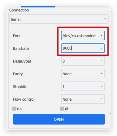
24GHz radar needs 5V power supply, otherwise the radar may not work properly.
After a successful connection, you will see the radar sending a steady stream of messages.

Paste the complete data frame we obtained in step3 onto the send area of the software. Then click Send.
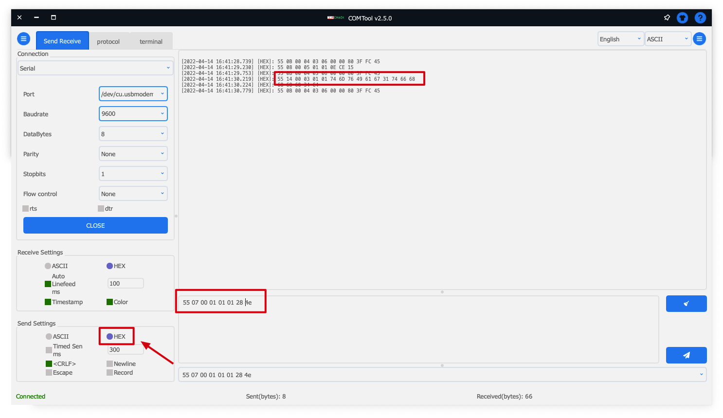
You can look out for a set of data returned with the third element being 0x03. This set of data is the information obtained after the query. If you send data that adjusts the parameters of the radar, it will also return such information.
If you choose ASCII as the format for sending data, each data set needs to be prefixed with 0x. If you choose HEX, then each set of data does not need to be prefixed with 0x.
Troubleshooting
FAQ1: How to apply the code to Seeeduino (or Arduino)?
Because of the different hardware design, the serial port of XIAO series or Wio Terminal are named Serial1, while Seeeduino or Arduino need to use soft serial port. If you want to use the radar for Seeeduino, you can change the soft serial port or use pins 2 (RX) and 3 (TX).

FAQ2: What should I do if XIAO BLE and Radar collect data for a long time and cannot upload the code?
At this time, you can use your finger to lightly press the reset button on top of XIAO BLE to re-upload the program to run.
Resources
- [PDF] Sleep Breathing Radar Sensor Datasheet
- [PDF] 24GHz Sleep Breathing Radar Sensor User Manual
- [ZIP] 24GHz Respiratory schematic
- [PPTX] Seeed mmWave sensor series V2.0
Tech Support & Product Discussion
Thank you for choosing our products! We are here to provide you with different support to ensure that your experience with our products is as smooth as possible. We offer several communication channels to cater to different preferences and needs.