Pin Multiplexing
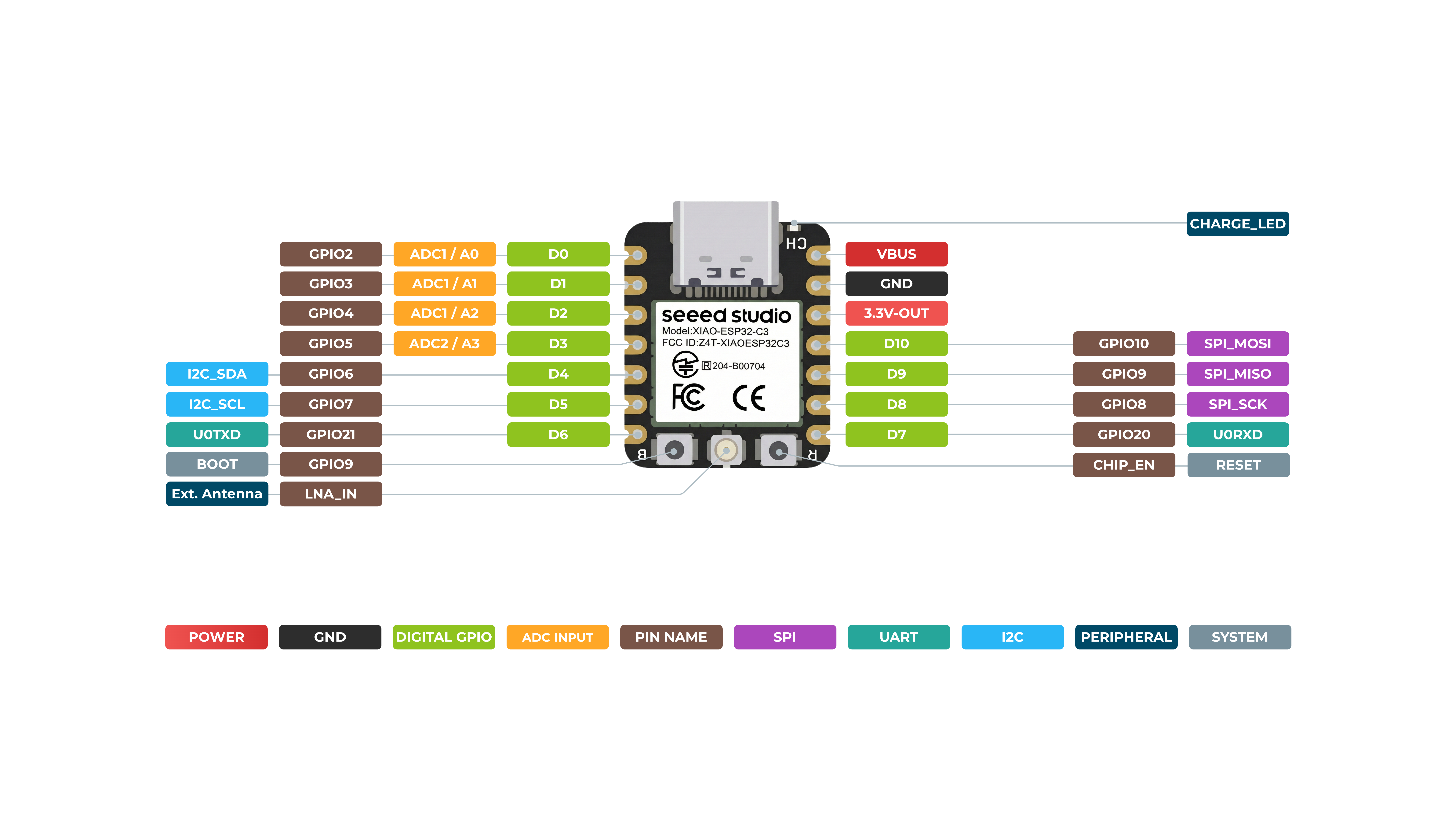
Seeed Studio XIAO ESP32C3 has rich interfaces. There are 11 digital I/O that can be used as PWM pins and 4 analog inputs that can be used as ADC pins. It supports four serial communication interfaces such as UART, I2C, SPI and I2S. This wiki will be helpful to learn about these interfaces and implement them in your next projects!
Hardware overview
*A3(GP105) - Uses ADC2, which may become inoperative due to false sampling signals. For reliable analog reads, use ADC1(A0/A1/A2) instead. Refer to the ESP32-C3 datasheet.
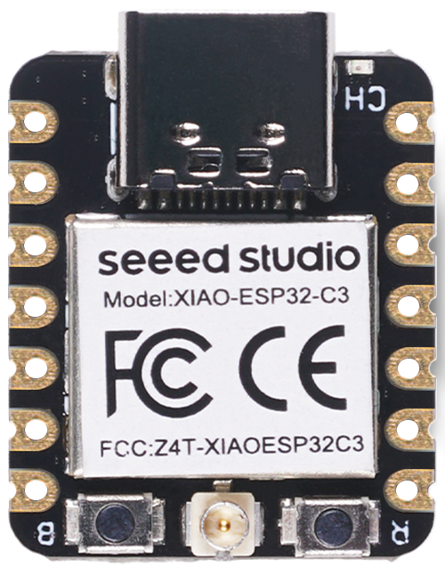
Front
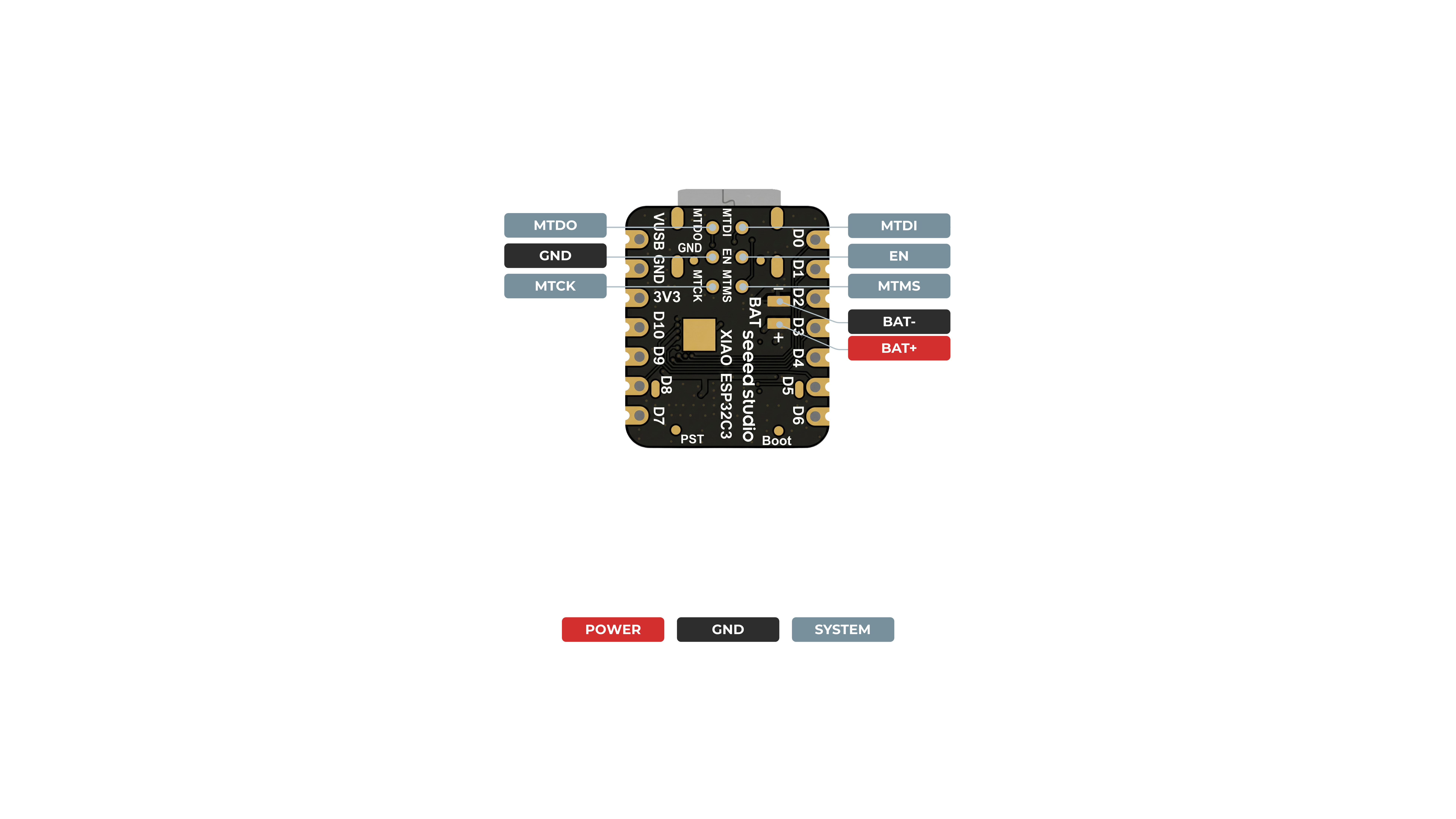
Back
Digital
Connect a pushbutton to Pin D6 and an LED to Pin D10. Then upload the following code to control the ON/OFF of LED using the pushbutton.
const int buttonPin = D6;     // pushbutton connected to digital pin 6
const int ledPin =  D10;      // LED connected to digital pin 10

int buttonState = 0;         // variable for reading the pushbutton status

void setup() {
  // initialize the LED pin as an output:
  pinMode(ledPin, OUTPUT);
  // initialize the pushbutton pin as an input:
  pinMode(buttonPin, INPUT);
}

void loop() {
  // read the state of the pushbutton value:
  buttonState = digitalRead(buttonPin);

  // check if the pushbutton is pressed. If it is, the buttonState is HIGH:
  if (buttonState == HIGH) {
    // turn LED on:
    digitalWrite(ledPin, HIGH);
  } else {
    // turn LED off:
    digitalWrite(ledPin, LOW);
  }
}
Digital as PWM
Connect an LED to Pin D10. Then upload the following code to see the LED gradually fading.
int ledPin = D10;    // LED connected to digital pin 10

void setup() {
  // declaring LED pin as output
  pinMode(ledPin, OUTPUT);
}

void loop() {
  // fade in from min to max in increments of 5 points:
  for (int fadeValue = 0 ; fadeValue <= 255; fadeValue += 5) {
    // sets the value (range from 0 to 255):
    analogWrite(ledPin, fadeValue);
    // wait for 30 milliseconds to see the dimming effect
    delay(30);
  }

  // fade out from max to min in increments of 5 points:
  for (int fadeValue = 255 ; fadeValue >= 0; fadeValue -= 5) {
    // sets the value (range from 0 to 255):
    analogWrite(ledPin, fadeValue);
    // wait for 30 milliseconds to see the dimming effect
    delay(30);
  }
}
Analog
Connect a potentiometer to Pin A0 and an LED to Pin D10. Then upload the following code to control the blinking interval of the LED by rotating the potentiometer knob.
The ADC mapping range is 0-2500mV.
const int sensorPin = A0;
const int ledPin =  D10;

void setup() {
  pinMode(sensorPin, INPUT);  // declare the sensorPin as an INPUT
  pinMode(ledPin, OUTPUT);   // declare the ledPin as an OUTPUT
}

void loop() {
  // read the value from the sensor:
  int sensorValue = analogRead(sensorPin);
  // turn the ledPin on
  digitalWrite(ledPin, HIGH);
  // stop the program for <sensorValue> milliseconds:
  delay(sensorValue);
  // turn the ledPin off:
  digitalWrite(ledPin, LOW);
  // stop the program for for <sensorValue> milliseconds:
  delay(sensorValue);
}
Serial - UART
Regular method - choose one of USB serial or UART0 serial to use
There are 2 serial interfaces on this board:
- USB Serial
- UART0 Serial
There is no Serial2 for XIAO ESP32 C3.
Also If you need to use Serial1, you must define the pins; otherwise, it may not receive data. For XIAO ESP32 series, use Serial1 as follows:
Serial1.begin(115200, SERIAL_8N1, D7, D6); // RX, TX
By default, USB serial is enabled, which means you can connect the board to a PC via USB Type-C and open serial monitor on Arduino IDE to view data sent via serial.
However, if you want to use UART0 as the serial, you need to connect pin D6 as the TX pin and pin D7 as RX pin with a USB-Serial adapter.
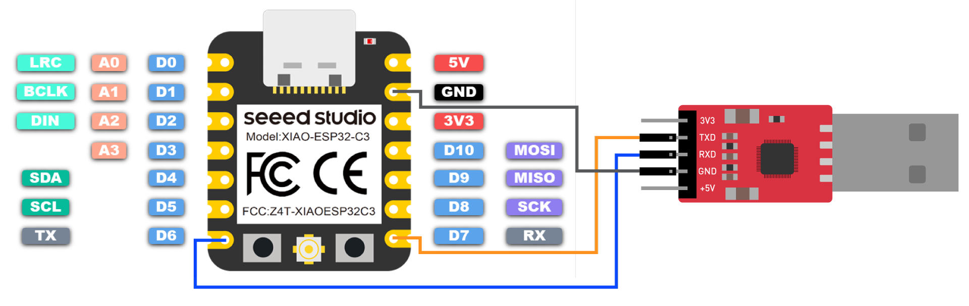
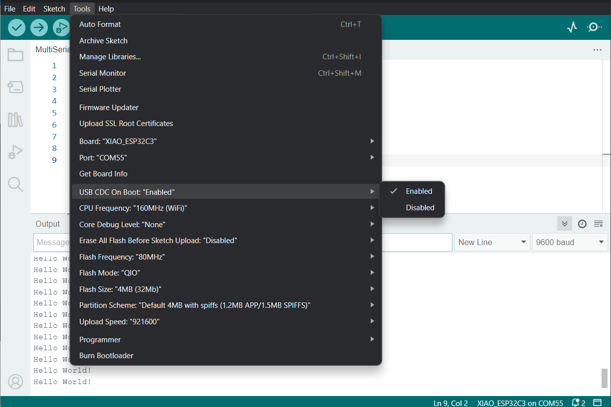
Also, you need to set USB CDC On Boot to Disabled from Arduino IDE.
NOTE: Change photo when board shows up on Arduino Board Manager
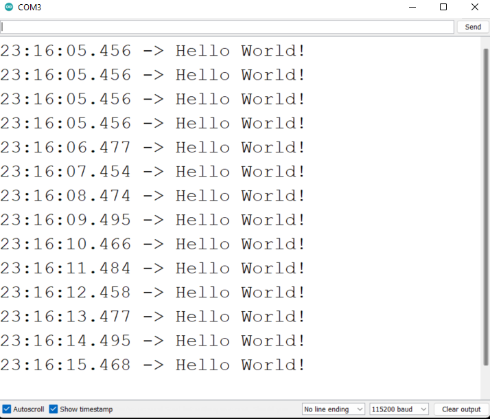
Upload the following code to Arduino IDE to send the string "Hello World!" via serial
void setup() {
    Serial.begin(115200);
    while (!Serial);
}

void loop() {
    Serial.println("Hello World!");
    delay(1000);
}
The output will be as follows on Arduino Serial Monitor
Special way - use USB serial and UART0/UART1 at the same time
Very often, we need to use UART sensors to connect to XIAO ESP32C3 hardware serial port to get data, and at the same time, you may need to use the USB serial to display the data on the serial monitor. This can be achieved by some special methods.
- Example program:
// Need this for the lower level access to set them up.
#include <HardwareSerial.h>

//Define two Serial devices mapped to the two internal UARTs
HardwareSerial MySerial0(0);
HardwareSerial MySerial1(1);

void setup()
{
    // For the USB, just use Serial as normal:
    Serial.begin(115200);

    // Configure MySerial0 on pins TX=D6 and RX=D7 (-1, -1 means use the default)
    MySerial0.begin(9600, SERIAL_8N1, -1, -1);
    MySerial0.print("MySerial0");

    // And configure MySerial1 on pins RX=D9, TX=D10
    MySerial1.begin(115200, SERIAL_8N1, 9, 10);
    MySerial1.print("MySerial1");
}

void loop()
{

}
As you can see, the XIAO ESP32C3 actually has three UARTs available.
In the following, we will take the 60GHz mmWave Sensor - Human Resting Breathing and Heartbeat Module, which is available for sale, as an example, and explain how to use the D6 and D7 hardware serial ports and the USB serial port.
Please be prepared for the following.
| XIAO ESP32C3 | 60GHz mmWave Sensor - Human Resting Breathing and Heartbeat Module |
|---|---|
 | 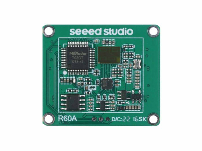 |
| Get One Now | Get One Now |
Download the sensor library to your computer. And add it to the Arduino IDE.
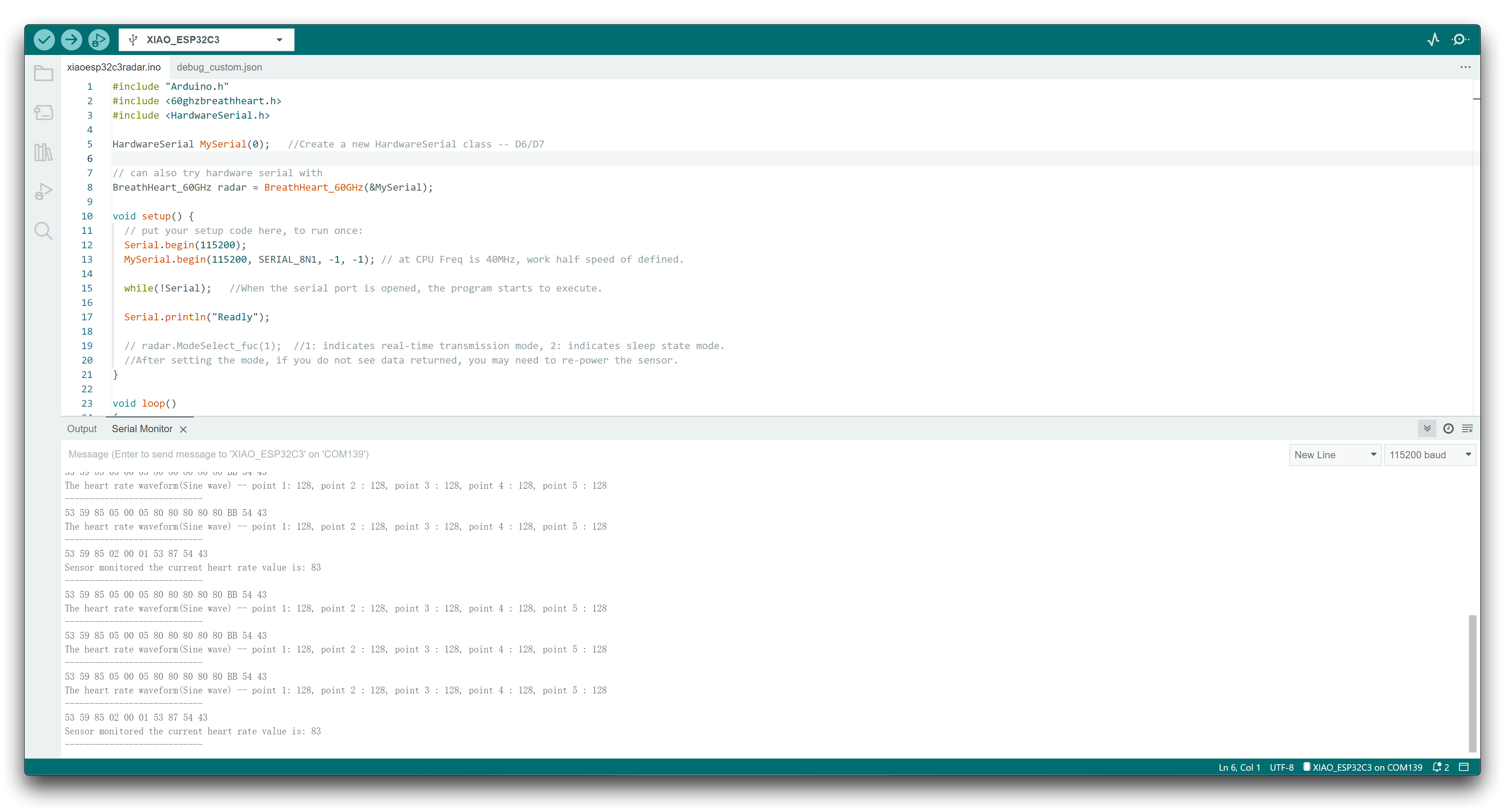
Here, we want to parse the heartbeat and respiration data information, then you can rewrite your program like this.
#include "Arduino.h"
#include <60ghzbreathheart.h>
#include <HardwareSerial.h>

HardwareSerial MySerial(0);   //Create a new HardwareSerial class -- D6/D7

// can also try hardware serial with
BreathHeart_60GHz radar = BreathHeart_60GHz(&MySerial);

void setup() {
  // put your setup code here, to run once:
  Serial.begin(115200);
  MySerial.begin(115200, SERIAL_8N1, -1, -1); // at CPU Freq is 40MHz, work half speed of defined.

  while(!Serial);   //When the serial port is opened, the program starts to execute.

  Serial.println("Readly");

  // radar.ModeSelect_fuc(1);  //1: indicates real-time transmission mode, 2: indicates sleep state mode.
  //After setting the mode, if you do not see data returned, you may need to re-power the sensor.
}

void loop()
{
  // put your main code here, to run repeatedly:
  radar.Breath_Heart();           //Breath and heartbeat information output
  if(radar.sensor_report != 0x00){
    switch(radar.sensor_report){
      case HEARTRATEVAL:
        Serial.print("Sensor monitored the current heart rate value is: ");
        Serial.println(radar.heart_rate, DEC);
        Serial.println("----------------------------");
        break;
      case HEARTRATEWAVE:  //Valid only when real-time data transfer mode is on
        Serial.print("The heart rate waveform(Sine wave) -- point 1: ");
        Serial.print(radar.heart_point_1);
        Serial.print(", point 2 : ");
        Serial.print(radar.heart_point_2);
        Serial.print(", point 3 : ");
        Serial.print(radar.heart_point_3);
        Serial.print(", point 4 : ");
        Serial.print(radar.heart_point_4);
        Serial.print(", point 5 : ");
        Serial.println(radar.heart_point_5);
        Serial.println("----------------------------");
        break;
      case BREATHNOR:
        Serial.println("Sensor detects current breath rate is normal.");
        Serial.println("----------------------------");
        break;
      case BREATHRAPID:
        Serial.println("Sensor detects current breath rate is too fast.");
        Serial.println("----------------------------");
        break;
      case BREATHSLOW:
        Serial.println("Sensor detects current breath rate is too slow.");
        Serial.println("----------------------------");
        break;
      case BREATHNONE:
        Serial.println("There is no breathing information yet, please wait...");
        Serial.println("----------------------------");
        break;
      case BREATHVAL:
        Serial.print("Sensor monitored the current breath rate value is: ");
        Serial.println(radar.breath_rate, DEC);
        Serial.println("----------------------------");
        break;
      case BREATHWAVE:  //Valid only when real-time data transfer mode is on
        Serial.print("The breath rate waveform(Sine wave) -- point 1: ");
        Serial.print(radar.breath_point_1);
        Serial.print(", point 2 : ");
        Serial.print(radar.breath_point_2);
        Serial.print(", point 3 : ");
        Serial.print(radar.breath_point_3);
        Serial.print(", point 4 : ");
        Serial.print(radar.breath_point_4);
        Serial.print(", point 5 : ");
        Serial.println(radar.breath_point_5);
        Serial.println("----------------------------");
        break;
    }
  }
  delay(200);                       //Add time delay to avoid program jam
}
Please upload the program, then open the serial monitor and set the baud rate to 115200.
Next, we can connect the sensor to the XIAO ESP32C3 using the following connection method.
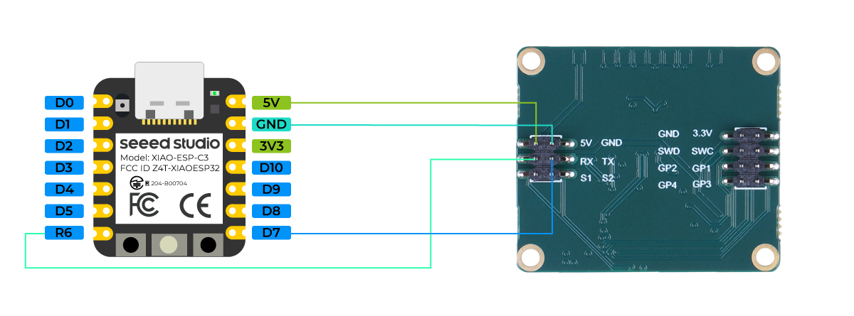
If all goes well, you will see data messages on the serial monitor.
Serial1 Usage
According to the above XIAO ESP32C3 Pin diagrams for specific parameters, we can observe that there are TX pin and RX pin. This is different from serial communication, but the usage is also very similar, except that a few parameters need to be added. So next, we will use the pins led out by the chip for serial communication.
Core Function that need to be include:
Serial1.begin(BAUD,SERIAL_8N1,RX_PIN,TX_PIN);-- enable Serial1,the function prototype :<Serial.Type>.begin(unsigned long baud, uint32_t config, int8_t rxPin, int8_t txPin);baud:baud rateconfig:Configuration bitrxPin:Receive PintxPin:Send Pin
It is worth nothing that if we use digital pin port to define,this place should be#define RX_PIN D7、#define TX_PIN D6,please refer to the pin diagrams of different XIAO Series for specific parameters.
Here is an example program:
#define RX_PIN D7
#define TX_PIN D6
#define BAUD 115200

void setup() {
    Serial1.begin(BAUD,SERIAL_8N1,RX_PIN,TX_PIN);
}

void loop() {
  if(Serial1.available() > 0)
  {
    char incominByte = Serial1.read();
    Serial1.print("I received : ");
    Serial1.println(incominByte);
  }
  delay(1000);
}
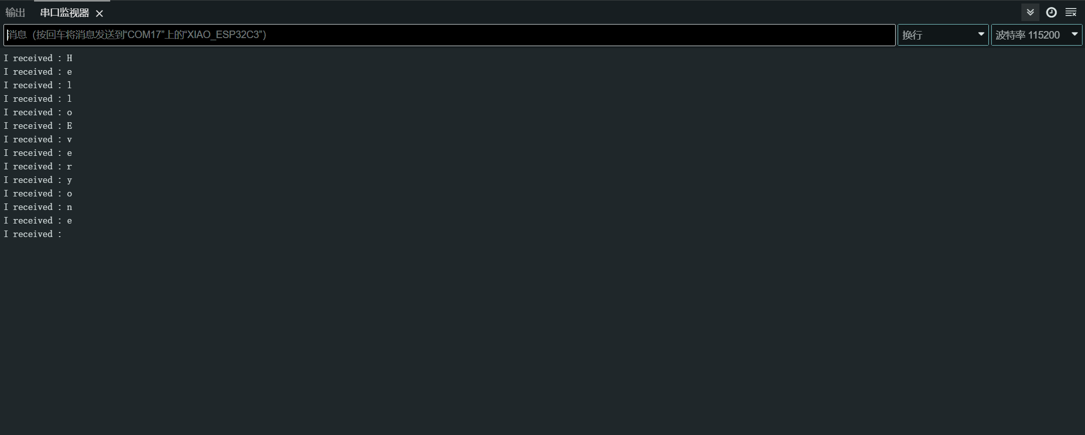
After uploading the program, open the Serial Monitor in Arduino IDE and set the baud rate to 115200.then,you can send content you want in the XIAO ESP32C3 through the serial monitor Serial ,and XIAO will print out each byte of the content you send.,In here,the content i entered is "Hello Everyone",my result chart is as follows
Software Serial
To use software serial, install the EspSoftwareSerial library.
Currently we recommend version 7.0.0 of the EspSoftwareSerial library. Other versions may have varying degrees of problems that prevent the soft serial port from working properly.
#include <SoftwareSerial.h>

SoftwareSerial mySerial(D7, D6); // RX, TX

void setup() {
  Serial.begin(9600);
  mySerial.begin(9600);
}

void loop() {
  if (mySerial.available()) {
    char data = mySerial.read();
    Serial.print("Received via software serial: ");
    Serial.println(data);
  }

  if (Serial.available()) {
    char data = Serial.read();
    mySerial.print("Received via hardware serial: ");
    mySerial.println(data);
  }
}
This example sets up software serial on pins D7 (RX) and D6 (TX) at 9600 baud. It monitors both the hardware serial (USB) and software serial ports, echoing received data between them.
I2C
Hardware connection
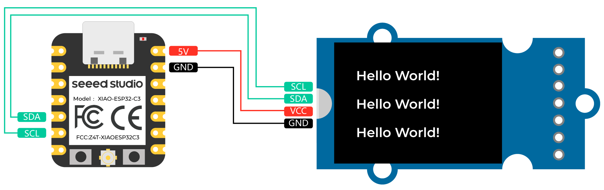
Connect a Grove - OLED Yellow&Blue Display 0.96 (SSD1315) to XIAO ESP32C3 by following the hardware connection as follows.
| Grove - OLED Yellow&Blue Display 0.96 (SSD1315) | XIAO ESP32C3 |
|---|---|
| SCL | SCL |
| SDA | SDA |
| VCC | 5V |
| GND | GND |
Software setup
-
Step 1. Open Arduino IDE, navigate to
Sketch > Include Library > Manage Libraries... -
Step 2. Search for u8g2 and install it

- Step 3. Upload the following code to display text strings on the OLED Display
//#include <Arduino.h>
#include <U8g2lib.h>

#ifdef U8X8_HAVE_HW_SPI
#include <SPI.h>
#endif
#ifdef U8X8_HAVE_HW_I2C
#include <Wire.h>
#endif

U8G2_SSD1306_128X64_NONAME_F_SW_I2C u8g2(U8G2_R0, /* clock=*/ SCL, /* data=*/ SDA, /* reset=*/ U8X8_PIN_NONE);    //Low spped I2C

void setup(void) {
  u8g2.begin();
//  u8x8.setFlipMode(1);   // set number from 1 to 3, the screen word will rotary 180
}

void loop(void) {
  u8g2.clearBuffer();                   // clear the internal memory
  u8g2.setFont(u8g2_font_ncenB08_tr);   // choose a suitable font
  u8g2.drawStr(0,15,"Hello World!");    // write something to the internal memory
  u8g2.drawStr(0,30,"Hello World!");
  u8g2.drawStr(0,40,"Hello World!");
  u8g2.sendBuffer();                    // transfer internal memory to the display
//  delay(1000);
}
SPI
Hardware connection
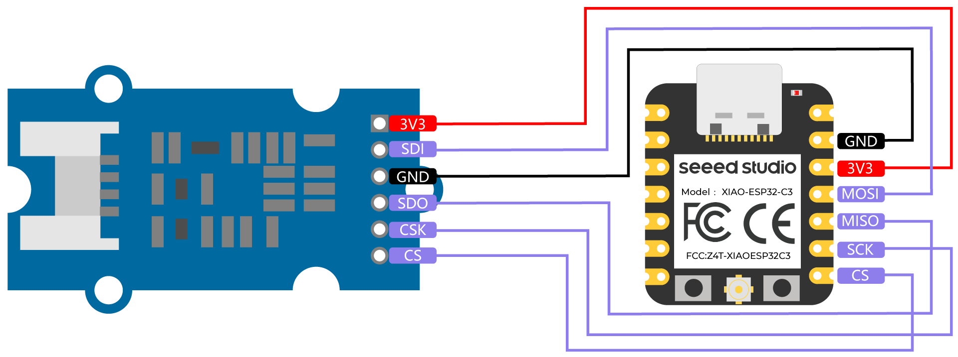
Connect a Grove - High Precision Barometric Pressure Sensor (DPS310) to XIAO ESP32C3 by following the hardware connection as follows.
| Grove - High Precision Barometric Pressure Sensor (DPS310) | XIAO ESP32C3 |
|---|---|
| 3V3 | 3V3 |
| SDI | MOSI |
| GND | GND |
| SDO | MISO |
| CSK | SCK |
| CS | CS |
Software setup
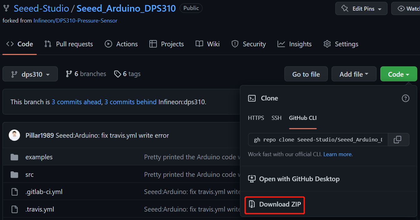
- Step 1. Download Seeed_Arduino_DPS310 Library as a zip file
- Step 2. Open Arduino IDE, navigate to
Sketch > Include Library > Add .ZIP Library...and open the downloaded zip file

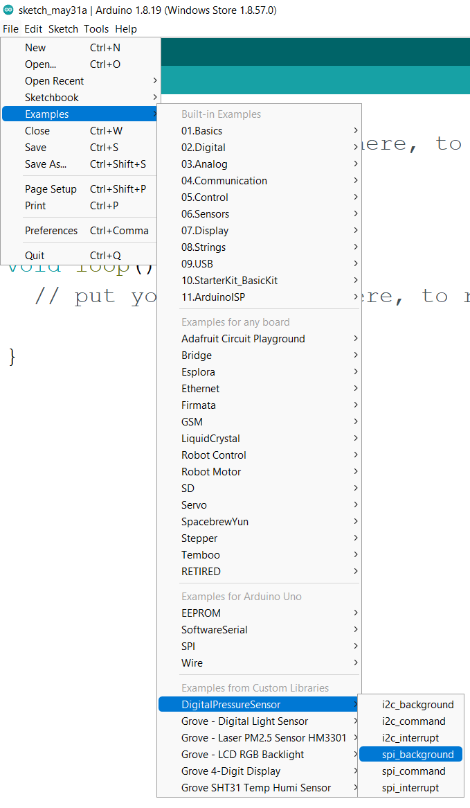
- Step 3. Navigate to
File > Examples > DigitalPressureSensor > spi_backgroundto open the spi_background example
Alternatively you can copy the code from below as well
#include <Dps310.h>

// Dps310 Opject
Dps310 Dps310PressureSensor = Dps310();

void setup() {
    //pin number of your slave select line
    //XMC2GO
    int16_t pin_cs = SS;
    //for XMC 1100 Bootkit  & XMC4700 Relax Kit uncomment the following line
    //int16_t pin_cs = 10;

    Serial.begin(9600);
    while (!Serial);


    //Call begin to initialize Dps310
    //The parameter pin_nr is the number of the CS pin on your Microcontroller
    Dps310PressureSensor.begin(SPI, pin_cs);

    //temperature measure rate (value from 0 to 7)
    //2^temp_mr temperature measurement results per second
    int16_t temp_mr = 2;
    //temperature oversampling rate (value from 0 to 7)
    //2^temp_osr internal temperature measurements per result
    //A higher value increases precision
    int16_t temp_osr = 2;
    //pressure measure rate (value from 0 to 7)
    //2^prs_mr pressure measurement results per second
    int16_t prs_mr = 2;
    //pressure oversampling rate (value from 0 to 7)
    //2^prs_osr internal pressure measurements per result
    //A higher value increases precision
    int16_t prs_osr = 2;
    //startMeasureBothCont enables background mode
    //temperature and pressure ar measured automatically
    //High precision and hgh measure rates at the same time are not available.
    //Consult Datasheet (or trial and error) for more information
    int16_t ret = Dps310PressureSensor.startMeasureBothCont(temp_mr, temp_osr, prs_mr, prs_osr);
    //Use one of the commented lines below instead to measure only temperature or pressure
    //int16_t ret = Dps310PressureSensor.startMeasureTempCont(temp_mr, temp_osr);
    //int16_t ret = Dps310PressureSensor.startMeasurePressureCont(prs_mr, prs_osr);


    if (ret != 0) {
        Serial.print("Init FAILED! ret = ");
        Serial.println(ret);
    } else {
        Serial.println("Init complete!");
    }
}


void loop() {
    uint8_t pressureCount = 20;
    float pressure[pressureCount];
    uint8_t temperatureCount = 20;
    float temperature[temperatureCount];

    //This function writes the results of continuous measurements to the arrays given as parameters
    //The parameters temperatureCount and pressureCount should hold the sizes of the arrays temperature and pressure when the function is called
    //After the end of the function, temperatureCount and pressureCount hold the numbers of values written to the arrays
    //Note: The Dps310 cannot save more than 32 results. When its result buffer is full, it won't save any new measurement results
    int16_t ret = Dps310PressureSensor.getContResults(temperature, temperatureCount, pressure, pressureCount);

    if (ret != 0) {
        Serial.println();
        Serial.println();
        Serial.print("FAIL! ret = ");
        Serial.println(ret);
    } else {
        Serial.println();
        Serial.println();
        Serial.print(temperatureCount);
        Serial.println(" temperature values found: ");
        for (int16_t i = 0; i < temperatureCount; i++) {
            Serial.print(temperature[i]);
            Serial.println(" degrees of Celsius");
        }

        Serial.println();
        Serial.print(pressureCount);
        Serial.println(" pressure values found: ");
        for (int16_t i = 0; i < pressureCount; i++) {
            Serial.print(pressure[i]);
            Serial.println(" Pascal");
        }
    }

    //Wait some time, so that the Dps310 can refill its buffer
    delay(10000);
}
- Step 4. Upload the codes and open the Serial Monitor
Note: Once you upload the codes, it will not be executed automatically until you click Serial Monitor on the upper right corner of the Arduino window.
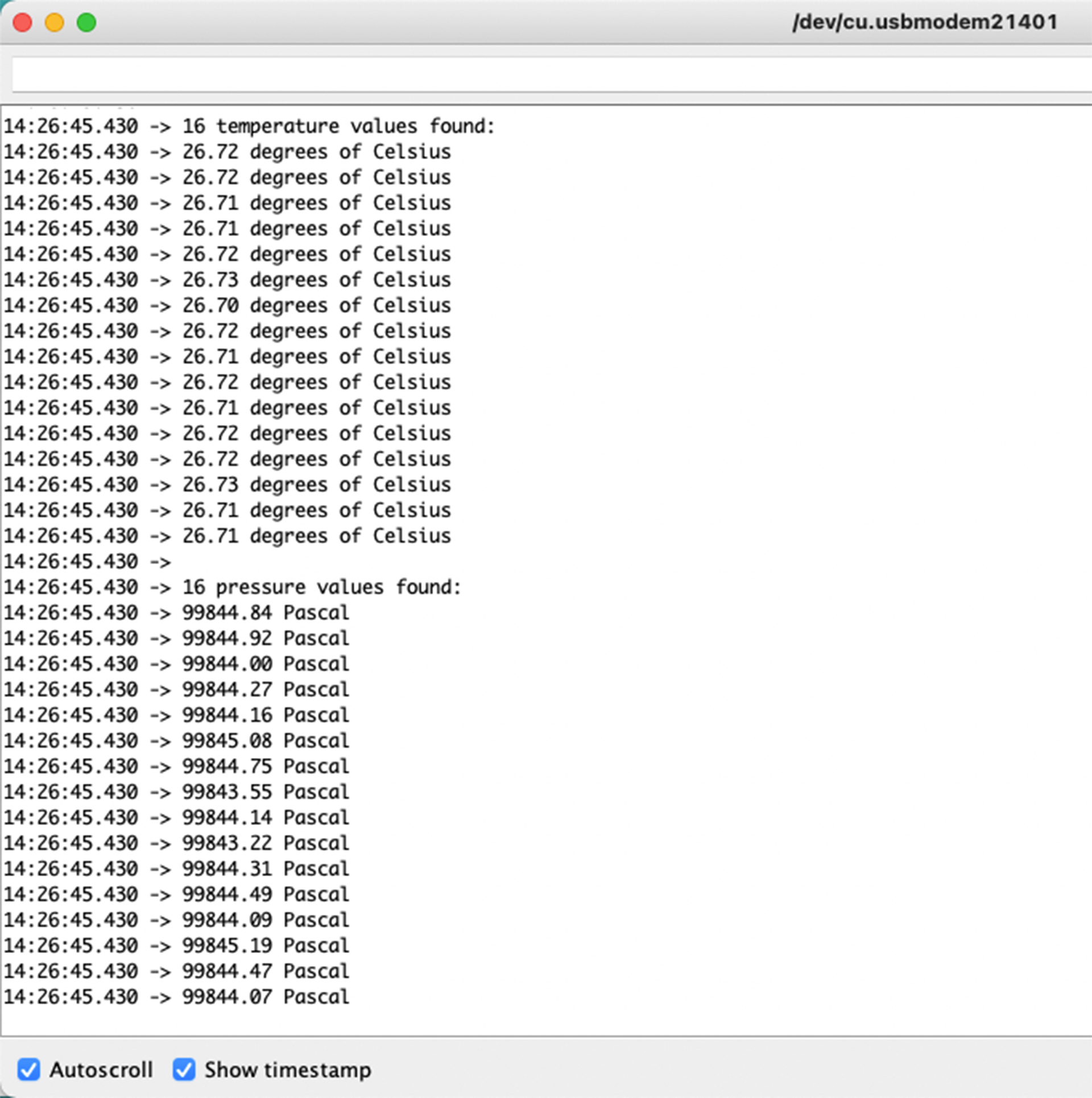
Now you will see the temperature and pressure data displayed one after the other on the serial monitor as above!
Note on XIAO ESP32C3 IO allocation
D9
The XIAO ESP32C3's D9 connects to the ESP32-C3's GPIO9 (15), pull-up resistor (R6), and BOOT button.The BOOT button (and RESET button) allows you to manually switch the ESP32-C3's Boot Mode.
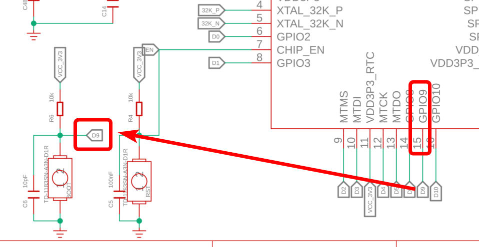
Pressing the BOOT button connects D9 to GND. So it is better to use D9 as a switch input.
D6
D6 of the XIAO ESP32C3 is connected to U0TXD (28) of the ESP32-C3. The operating status of the 1st/2nd stage bootloader is output as text to U0TXD.
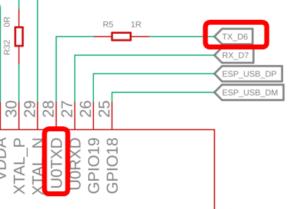
D6 is set as a UART output at startup, so if you use D6 as an input, you may accidentally generate a high current. So it is recommended to use the D6 pin only in output mode.
However, since this D6 is a UART output, you have to be careful about a few things: one is that it is HIGH in standby mode when not communicating. The other is the text output of the 1st/2nd stage bootloader. The signal flaps HIGH/LOW immediately after start-up and must be counteracted if necessary.
So try not to use D6. (It's okay to use it after you understand it, of course.)
D8
D8 of the Seeed Studio XIAO ESP32C3 is connected to GPIO8 (14) of the ESP32-C3.
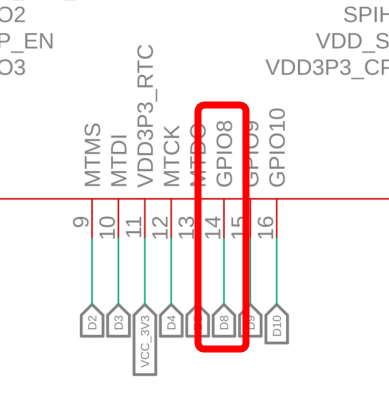
GPIO8 is referenced when the boot mode is set to download boot by holding down the BOOT button and must be HIGH at that time. (Here it says: "The strapping combination of GPIO8 = 0 and GPIO9 = 0 is invalid and will trigger unexpected behaviour.")
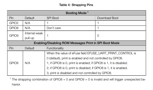
If you use download boot, add a pullup resistor to make GPIO8 HIGH at boot time.
A special thanks to SeeedJP colleague matsujirushi for testing and contributing to this section. Here is the reference link to the original article.