Develop SenseCAP Indicator both chips with Arduino
The SenseCAP Indicator is a 4-inch touch screen device that is powered by the ESP32 and RP2040 dual MCUs. ESP32 and RP2040 are both highly capable microcontrollers that offer a range of features and functions.
This tutorial will guide you to develop your own custom project/firmware for the Sensecap Indicator using the simplicity and Flexibility of the Arduino Framework.
Hardware Preparation
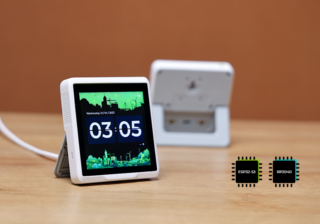
I am using SenseCAP Indicator as the hardware here and there are four types of sensors(CO2, Temp, Humi, TVOC) on it. The contents here should include:
| SenseCAP Indicator D1S |
|---|
 |
Hardware Overview and Develop Knowledge
The Indicator is designed with two MCU where there are RP2040 and ESP32S3 working at the same time.
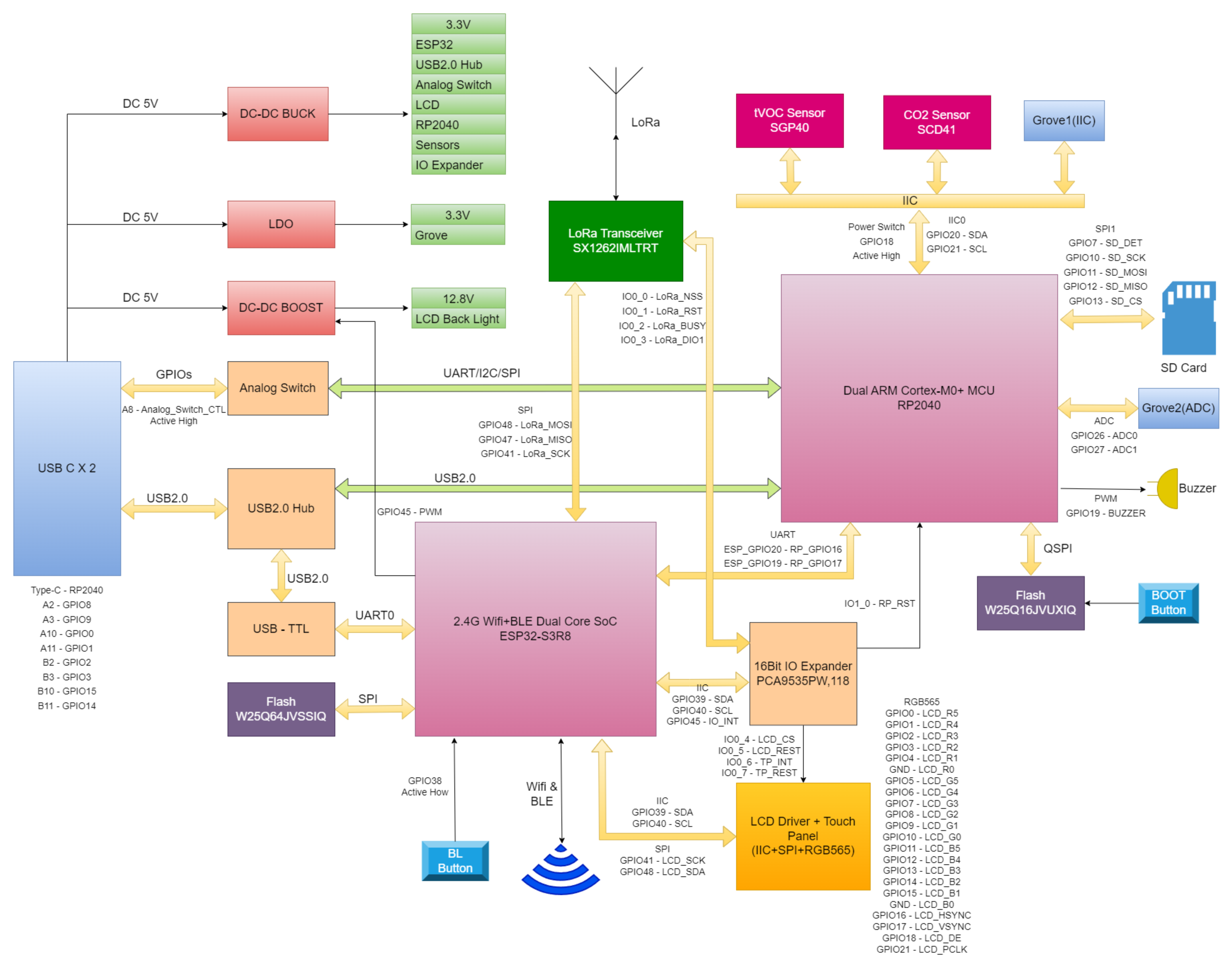
Based on the diagram above we know that:
- All the sensors are connected to RP2040 Microcontroller using I2C protocol
- There is one I2C IO expander module using the PCA9535 IC
- The screen are connected to ESP32S3 microcontroller with 2 Pin (CS, RESET) connected to the PCA9535 I2C expander
- The RP2040 are connected to the ESP32S3 via pin 20 and pin 19 on the ESP32S3 using UART Interfaces
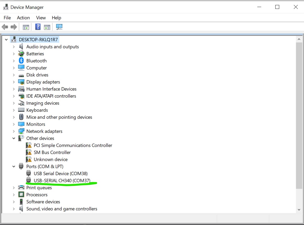
Thus, if the Sensecap Indicator plugged into the Computer you will be presented with 2 Serial Port one for the RP2040 and one for the ESP32S3. The one with the information USB-SERIAL CH340 is the one that's connected to the ESP32S3 and this is the one will be use for the rest of the tutorial.
Software Preparation
We are using Arduino here.
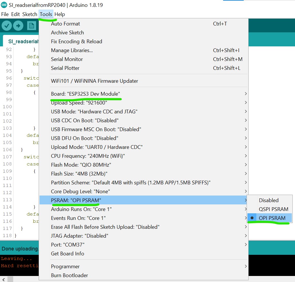
Before continuing with the tutorial, make sure the following steps are completed in the Arduino IDE:
- ESP32 board definition: Ensure the ESP32 board definition is installed and updated to the latest version. You can follow this guide if the ESP32 board is not yet in the Arduino IDE.
- Board selection: Choose the ESP32S3 Dev Module as the board definition.
- PSRAM: Enable the OPI PSRAM function in the Arduino IDE to ensure proper functionality of the screen.
Boards Used
To ensure compatibility with the project, please use the following versions of the boards:
- ESP32: version 3.1.2
- Raspberry Pi Pico Arduino: version 4.4.3
Libraries Used
TouchLib: version 0.0.2
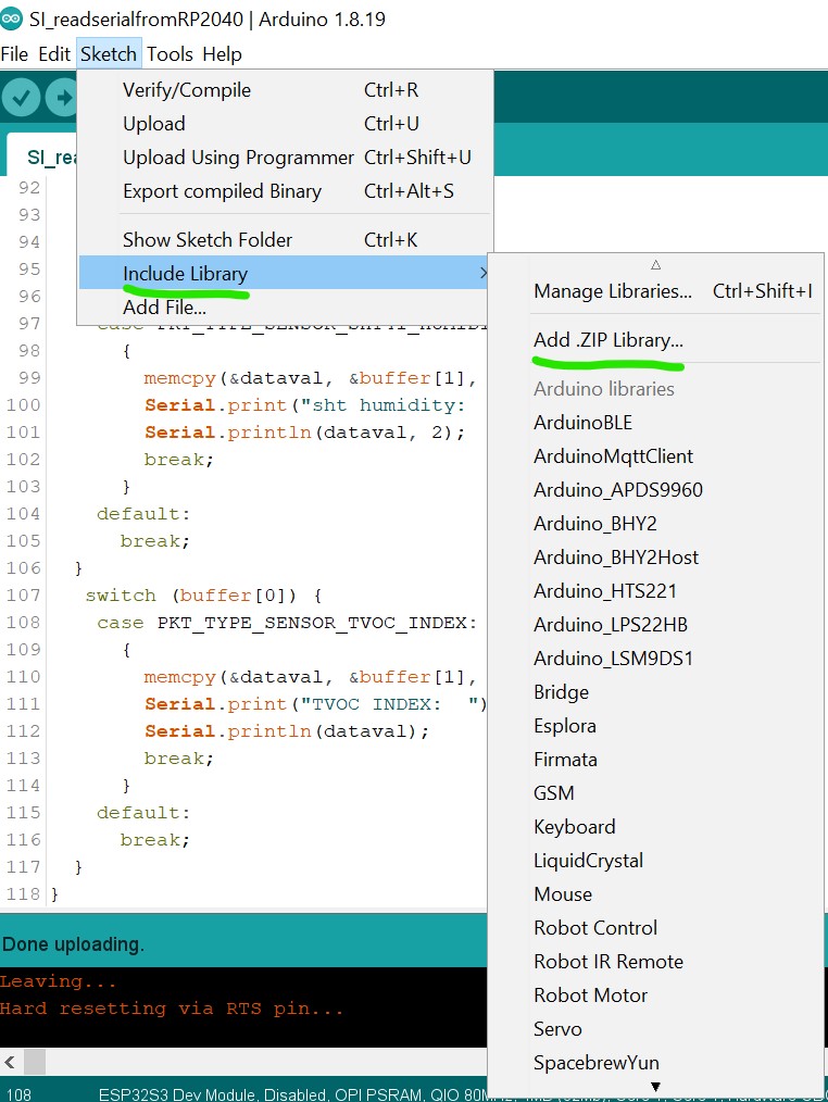
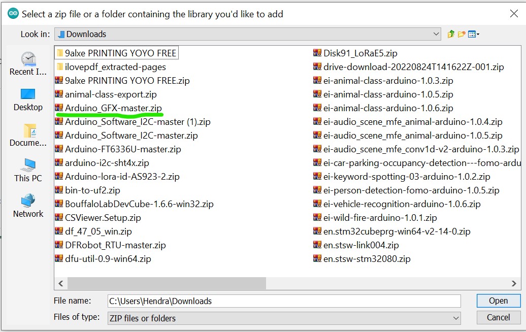
In order to integrate the touch driver and unify the touch interface, TouchLib library is needed. It is not available in the Arduino IDE Library Manager. You can download it manually from the TouchLib GitHub repository, and then add it to the Arduino IDE via Sketch > Include Library > Add .ZIP Library.
After the library is downloaded, open the Arduino IDE, go to the Sketch menu, choose "Add .ZIP Library," and then add the downloaded library into the IDE.
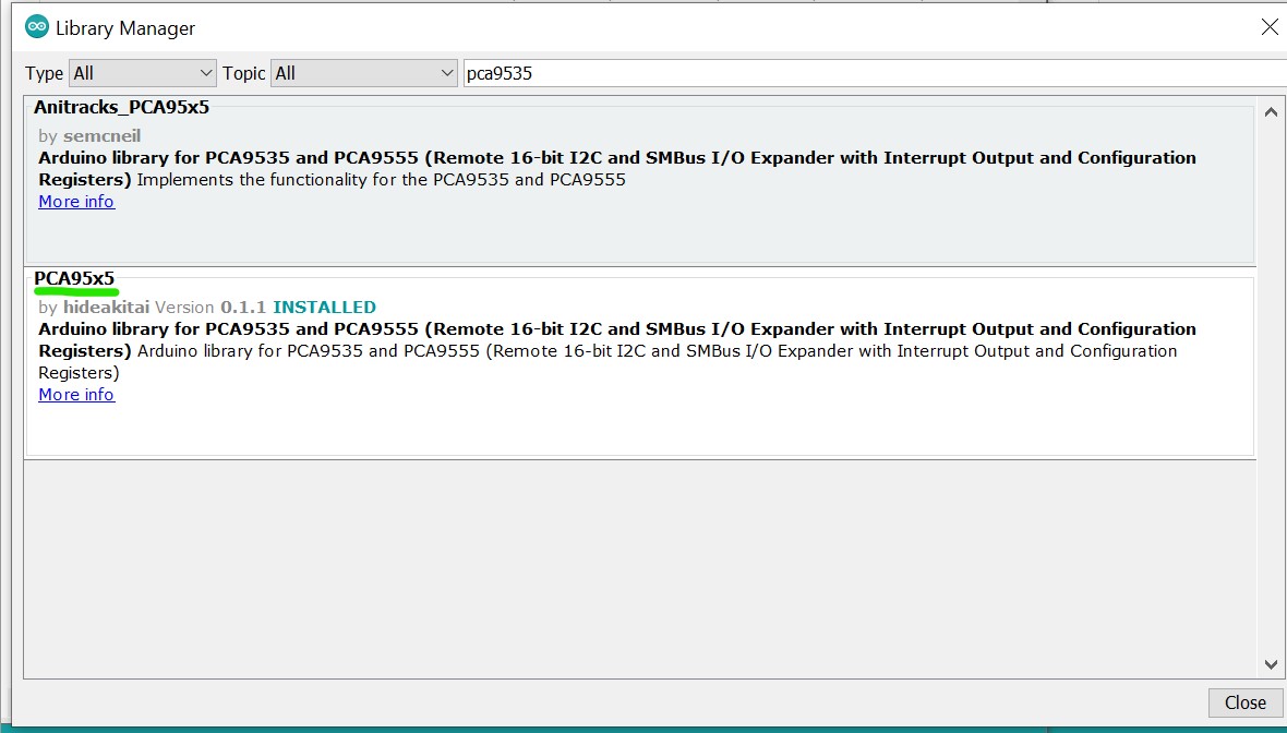
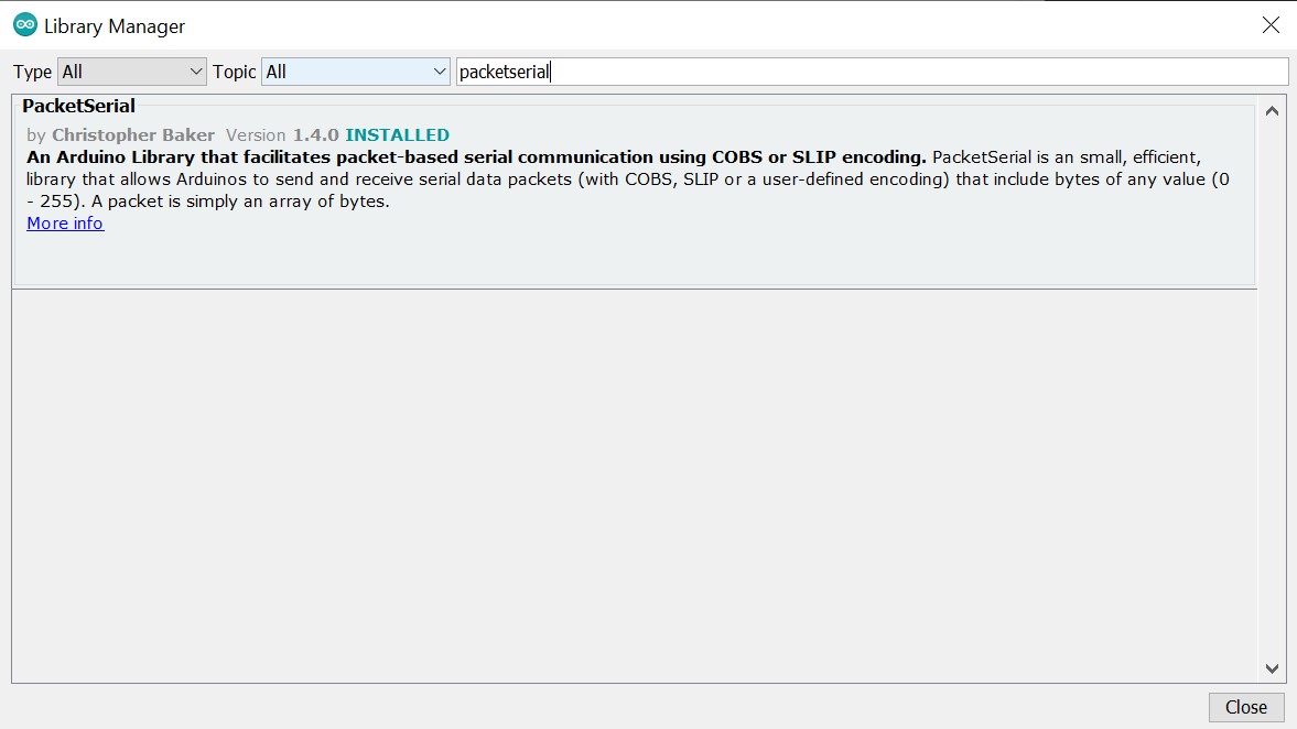
Similarly, for smooth integration, you need to check the same sketch menu and select "Manage Libraries," then search for the required libraries (e.g., "PCA9535," choose the one made by hidea kitai) and install them, while ensuring the following versions for all other required libraries:
- Adafruit TinyUSB: version 3.4.2
- Anitracks_PCA95x5: version 0.1.3
- GFX Library for Arduino: version 1.5.3
- PacketSerial: version 1.4.0
- lvgl: version 9.2.2
- PCA95x5: version 0.1.3
Ensure that these libraries and boards are installed in the Arduino IDE to avoid compatibility issues.
Getting Started
- New Tutorial (by LongDirtyAnimAlf)
- Old Tutorial (by Hendra)
After all the necessary libraries is installed upload the code below to test if the screen is working with the Arduino environment. You can upload the code below:
#include <Arduino_GFX_Library.h>
#include <PCA95x5.h>
#define GFX_BL DF_GFX_BL // default backlight pin, you may replace DF_GFX_BL to actual backlight pin

/* More dev device declaration: https://github.com/moononournation/Arduino_GFX/wiki/Dev-Device-Declaration */
#if defined(DISPLAY_DEV_KIT)
Arduino_GFX *gfx = create_default_Arduino_GFX();
#else /* !defined(DISPLAY_DEV_KIT) */

#define GFX_DEV_DEVICE ESP32_S3_RGB
#define GFX_BL 45
Arduino_DataBus *bus = new Arduino_SWSPI(
    GFX_NOT_DEFINED /* DC */, PCA95x5::Port::P04 /* CS */,
    41 /* SCK */, 48 /* MOSI */, GFX_NOT_DEFINED /* MISO */);

// option 1:
// Uncomment for 4" rect display
Arduino_ESP32RGBPanel *rgbpanel = new Arduino_ESP32RGBPanel(
    18 /* DE */, 17 /* VSYNC */, 16 /* HSYNC */, 21 /* PCLK */,
    4 /* R0 */, 3 /* R1 */, 2 /* R2 */, 1 /* R3 */, 0 /* R4 */,
    10 /* G0 */, 9 /* G1 */, 8 /* G2 */, 7 /* G3 */, 6 /* G4 */, 5 /* G5 */,
    15 /* B0 */, 14 /* B1 */, 13 /* B2 */, 12 /* B3 */, 11 /* B4 */,
    1 /* hsync_polarity */, 10 /* hsync_front_porch */, 8 /* hsync_pulse_width */, 50 /* hsync_back_porch */,
    1 /* vsync_polarity */, 10 /* vsync_front_porch */, 8 /* vsync_pulse_width */, 20 /* vsync_back_porch */);
Arduino_RGB_Display *gfx = new Arduino_RGB_Display(
    480 /* width */, 480 /* height */, rgbpanel, 2 /* rotation */, true /* auto_flush */,
    bus, GFX_NOT_DEFINED /* RST */, st7701_type1_init_operations, sizeof(st7701_type1_init_operations));

#endif /* !defined(DISPLAY_DEV_KIT) */
/*******************************************************************************
 * End of Arduino_GFX setting
 ******************************************************************************/

void setup(void)
{
  Serial.begin(115200);
  // Serial.setDebugOutput(true);
  // while(!Serial);
  Serial.println("Arduino_GFX Hello World example");

#ifdef GFX_EXTRA_PRE_INIT
  GFX_EXTRA_PRE_INIT();
#endif

  // Init Display
  if (!gfx->begin())
  {
    Serial.println("gfx->begin() failed!");
  }
  gfx->fillScreen(BLACK);

#ifdef GFX_BL
  pinMode(GFX_BL, OUTPUT);
  digitalWrite(GFX_BL, HIGH);
#endif

  gfx->setCursor(10, 10);
  gfx->setTextColor(RED);
  gfx->println("Sensecap Indicator");

  delay(5000); // 5 seconds
}

void loop()
{
  gfx->setCursor(random(gfx->width()), random(gfx->height()));
  gfx->setTextColor(random(0xffff), random(0xffff));
  gfx->setTextSize(random(6) /* x scale */, random(6) /* y scale */, random(2) /* pixel_margin */);
  gfx->println("Sensecap Indicator");

  delay(1000); // 1 second
}
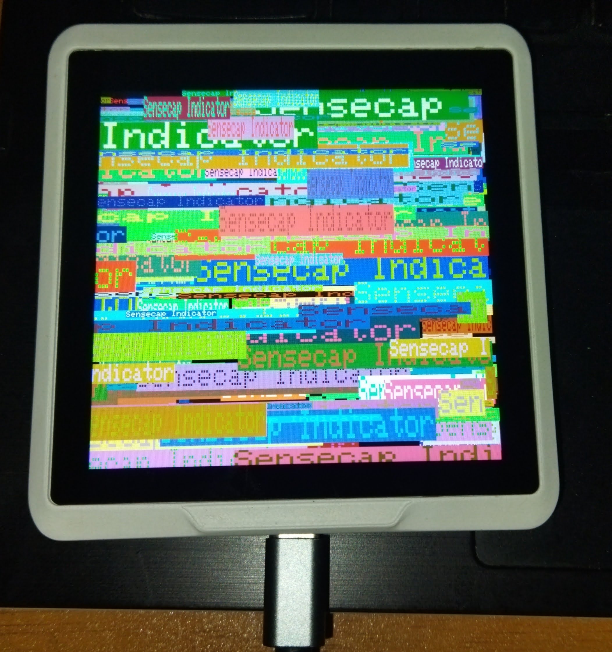
If everything goes well a "Sensecap Indicator" text will be printed randomly on the screen.
Creating Simple GUI Applications with SenseCap Indicator
The SenseCap Indicator has a powerful ESP32-S3 microcontroller and a high-resolution 480x480 display that makes it ideal for creating graphical user interfaces. Now, we'll continue our development with the SenseCap Indicator by exploring how to create interactive GUI applications using LVGL. You can download the complete project including source code and header files from the repository: Download SenseCap Indicator LVGL Project
After downloading and extracting the project files, upload the following code to create a basic multi-screen GUI application:
/*Using LVGL with Arduino requires some extra steps:
 *Be sure to read the docs here: https://docs.lvgl.io/master/get-started/platforms/arduino.html
 Install: lvgl*/

// This define is sometimes missing when using old ESP32-IDF version
//#define ESP_INTR_CPU_AFFINITY_AUTO 0

#include <Arduino.h>
#include <lvgl.h>
#include <Arduino_GFX_Library.h>
#include <PacketSerial.h>
#include "Indicator_Extender.h"
#include "Indicator_SWSPI.h"
#include "ui.h"
#include "touch.h"

#define HOR_RES 480
#define VER_RES 480

#define PACKET_UART_RXD 20
#define PACKET_UART_TXD 19

#define BUTTON_PIN 38

#define GFX_DEV_DEVICE ESP32_S3_RGB
#define RGB_PANEL
#define GFX_BL 45
Arduino_DataBus *bus = new Indicator_SWSPI(
    GFX_NOT_DEFINED /* DC */, EXPANDER_IO_LCD_CS /* CS */,
    SPI_SCLK /* SCK */, SPI_MOSI /* MOSI */, GFX_NOT_DEFINED /* MISO */);

Arduino_ESP32RGBPanel *rgbpanel = new Arduino_ESP32RGBPanel(
    18 /* DE */, 17 /* VSYNC */, 16 /* HSYNC */, 21 /* PCLK */,
    4 /* R0 */, 3 /* R1 */, 2 /* R2 */, 1 /* R3 */, 0 /* R4 */,
    10 /* G0 */, 9 /* G1 */, 8 /* G2 */, 7 /* G3 */, 6 /* G4 */, 5 /* G5 */,
    15 /* B0 */, 14 /* B1 */, 13 /* B2 */, 12 /* B3 */, 11 /* B4 */,
    1 /* hsync_polarity */, 10 /* hsync_front_porch */, 8 /* hsync_pulse_width */, 50 /* hsync_back_porch */,
    1 /* vsync_polarity */, 10 /* vsync_front_porch */, 8 /* vsync_pulse_width */, 20 /* vsync_back_porch */);
Arduino_RGB_Display *gfx = new Arduino_RGB_Display(
    HOR_RES /* width */, VER_RES /* height */, rgbpanel, 0 /* rotation */, false /* auto_flush */,
    bus, GFX_NOT_DEFINED /* RST */, st7701_indicator_init_operations, sizeof(st7701_indicator_init_operations));


COBSPacketSerial myPacketSerial;

void onPacketReceived(const uint8_t* buffer, size_t size);

uint32_t millis_cb(void)
{
  return millis();
}

/*Read the touchpad*/
void my_touchpad_read(lv_indev_t *indev, lv_indev_data_t *data)
{
  if (touch_has_signal())
  {
    if (touch_touched())
    {
      data->state = LV_INDEV_STATE_PRESSED;

      /*Set the coordinates*/
      data->point.x = touch_last_x;
      data->point.y = touch_last_y;
    }
    else if (touch_released())
    {
      data->state = LV_INDEV_STATE_RELEASED;
    }
  }
  else
  {
    data->state = LV_INDEV_STATE_RELEASED;
  }
}

// Main buttons event handler
static void event_handler(lv_event_t * e)
{
  lv_event_code_t code = lv_event_get_code(e);
  lv_obj_t * btn = lv_event_get_current_target_obj(e);

  if (btn != NULL)
  {
    if(code == LV_EVENT_CLICKED)
    {
      void * btn_no_void = (void*)lv_event_get_user_data(e);
      byte btn_no = (byte)((uintptr_t)btn_no_void);
      lv_obj_t * screen = lv_obj_get_screen(btn);
      if (screen != NULL)
      {
        Serial.println("Screen assigned");
        if (screen == screen2)
        {
          Serial.println("Screen 2");
          if (btn_no != 0)
          {
            Create_Screen3(event_handler);
            lv_screen_load(screen3);
          }
        }
        if (screen == screen3)
        {
          Serial.println("Screen 3");
          if (btn_no == 0)
          {
            lv_screen_load(screen2);
            lv_obj_delete(screen3);
          }
        }
      }
    }
  }
}

void setup()
{
  Serial.begin(115200);
  Serial.println("SenseCap Indicator startup");
  String LVGL_Arduino = String('V') + lv_version_major() + "." + lv_version_minor() + "." + lv_version_patch();
  Serial.println(LVGL_Arduino);

  pinMode(BUTTON_PIN, INPUT);

  // Init Indicator hardware
  extender_init();

  myPacketSerial.begin(115200);
  Serial1.begin(115200, SERIAL_8N1, PACKET_UART_RXD, PACKET_UART_TXD);
  myPacketSerial.setStream(&Serial1);
  myPacketSerial.setPacketHandler(&onPacketReceived);

  // Init Display
  if (!gfx->begin(12000000L))
  {
    Serial.println("gfx->begin() failed!");
    Serial.println("Expect sever errors !!!");
  }
  gfx->fillScreen(RGB565_BLACK);

#ifdef GFX_BL
  pinMode(GFX_BL, OUTPUT);
  digitalWrite(GFX_BL, HIGH);
#endif
  lv_init();

  /*Set a tick source so that LVGL will know how much time elapsed. */
  lv_tick_set_cb(millis_cb);

  /* register print function for debugging */
#if LV_USE_LOG != 0
  lv_log_register_print_cb(my_print);
#endif

  lv_screen_init(gfx, HOR_RES, VER_RES);
  //lv_display_set_rotation(disp, LV_DISPLAY_ROTATION_0);
  //lv_display_set_antialiasing(disp,false);

  // Init touch device
  touch_init(HOR_RES, VER_RES, 0); // rotation will be handled by lvgl
  /*Initialize the input device driver*/
  lv_indev_t *indev = lv_indev_create();
  lv_indev_set_type(indev, LV_INDEV_TYPE_POINTER); /*Touchpad should have POINTER type*/
  lv_indev_set_read_cb(indev, my_touchpad_read);

  Screen2Create(event_handler);

  lv_screen_load(screen2);

  Serial.println("Setup done");
}

void loop()
{
  static TickType_t xLastWakeTime = xTaskGetTickCount();

  /*
  unsigned long startTime = millis();
  while (digitalRead(BUTTON_PIN) == LOW)
  {
    if (millis() - startTime >= 10000)
    {
      ESP.restart();
      //esp_restart();
    }
  }
  */

  myPacketSerial.update();
  // Check for a receive buffer overflow (optional).
  if (myPacketSerial.overflow())
  {
    // Send an alert via a pin (e.g. make an overflow LED) or return a
    // user-defined packet to the sender.
  }

  lv_task_handler(); /* let the GUI do its work */

  // Simple delay always 5ms
  //delay(5);

  // This delay will adapt to the time consumed in the above tasks
  // If these tasks consume time, it will delay shorter
  vTaskDelayUntil( &xLastWakeTime, ( 5 / portTICK_PERIOD_MS ) );
}

void onPacketReceived(const uint8_t* buffer, size_t size)
{
  if (size < 1) {
    return;
  }

  byte index = 0;
  byte Command = buffer[index++];
  if (Command == 0x55)
  {
    long Temperature = 0;
    long Humidity = 0;

    memcpy(&Temperature, &buffer[index], sizeof(Temperature));
    index += sizeof(Temperature);
    memcpy(&Humidity, &buffer[index], sizeof(Humidity));
    index += sizeof(Humidity);

    Screen2AddData(Temperature,Humidity);
  }
}
After uploading the code, open the Serial Monitor and set the baud rate to 115200. You should see initialization messages and your GUI will appear on the display, showing Screen2 with any temperature and humidity data received through the UART connection.
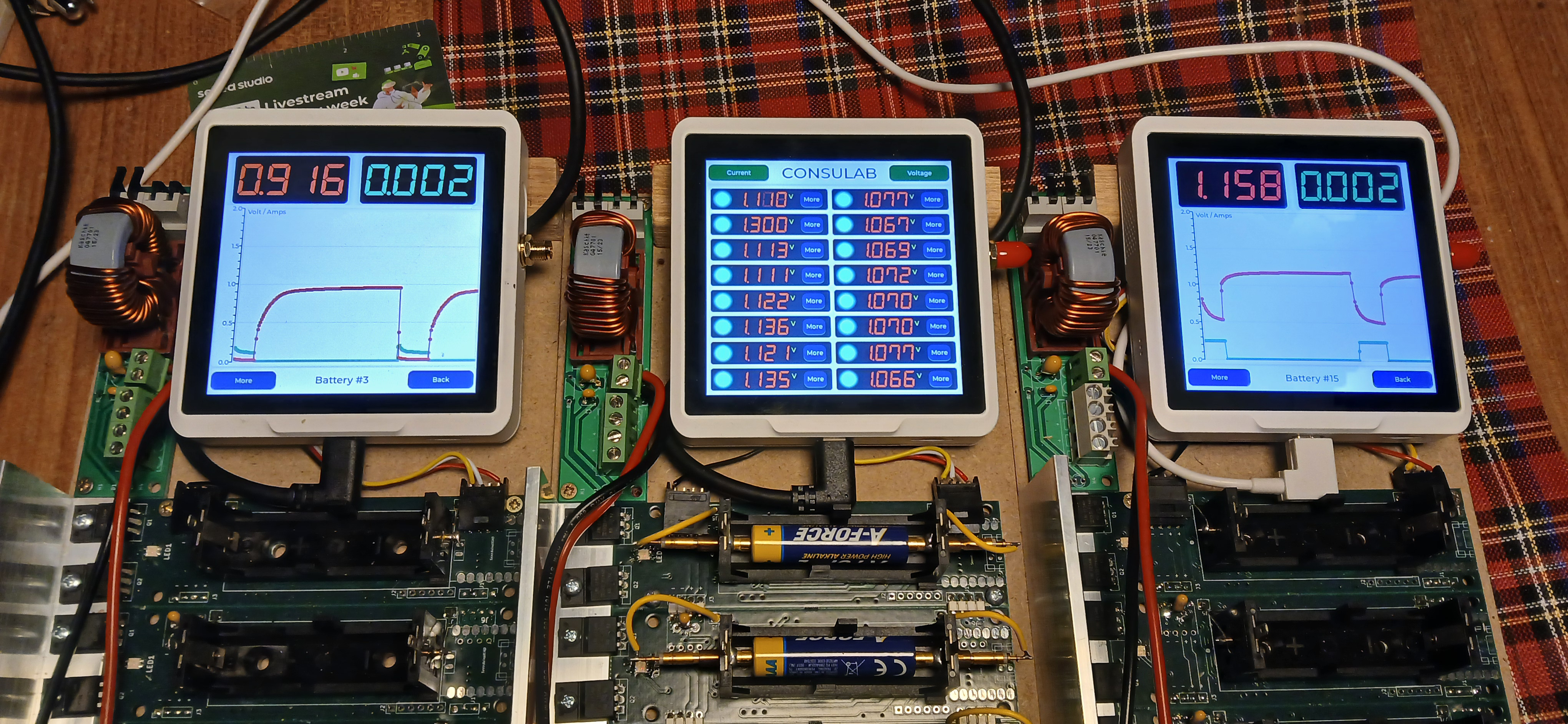
Advanced GUI Application with Multiple Screens and Data Visualization
The second example builds upon the basic application by adding more sophisticated features including battery monitoring, dynamic data visualization, and color-coded status indicators. You can download the complete project including source code and header files from the repository: Download SenseCap Indicator LVGL Project
To implement this version, upload the following code:
/*Using LVGL with Arduino requires some extra steps:
 *Be sure to read the docs here: https://docs.lvgl.io/master/get-started/platforms/arduino.html
 Install: lvgl*/

// This define is sometimes missing when using old ESP32-IDF version
//#define ESP_INTR_CPU_AFFINITY_AUTO 0

#include <Arduino.h>
#include <lvgl.h>
#include <Arduino_GFX_Library.h>
#include <PacketSerial.h>
#include "Indicator_Extender.h"
#include "Indicator_SWSPI.h"
#include "ui.h"
#include "touch.h"
#include "shared.h"

#define HOR_RES 480
#define VER_RES 480

#define PACKET_UART_RXD 20
#define PACKET_UART_TXD 19

#define BUTTON_PIN 38

#define GFX_DEV_DEVICE ESP32_S3_RGB
#define RGB_PANEL
#define GFX_BL 45
Arduino_DataBus *bus = new Indicator_SWSPI(
    GFX_NOT_DEFINED /* DC */, EXPANDER_IO_LCD_CS /* CS */,
    SPI_SCLK /* SCK */, SPI_MOSI /* MOSI */, GFX_NOT_DEFINED /* MISO */);

Arduino_ESP32RGBPanel *rgbpanel = new Arduino_ESP32RGBPanel(
    18 /* DE */, 17 /* VSYNC */, 16 /* HSYNC */, 21 /* PCLK */,
    4 /* R0 */, 3 /* R1 */, 2 /* R2 */, 1 /* R3 */, 0 /* R4 */,
    10 /* G0 */, 9 /* G1 */, 8 /* G2 */, 7 /* G3 */, 6 /* G4 */, 5 /* G5 */,
    15 /* B0 */, 14 /* B1 */, 13 /* B2 */, 12 /* B3 */, 11 /* B4 */,
    1 /* hsync_polarity */, 10 /* hsync_front_porch */, 8 /* hsync_pulse_width */, 50 /* hsync_back_porch */,
    1 /* vsync_polarity */, 10 /* vsync_front_porch */, 8 /* vsync_pulse_width */, 20 /* vsync_back_porch */);
Arduino_RGB_Display *gfx = new Arduino_RGB_Display(
    HOR_RES /* width */, VER_RES /* height */, rgbpanel, 0 /* rotation */, false /* auto_flush */,
    bus, GFX_NOT_DEFINED /* RST */, st7701_indicator_init_operations, sizeof(st7701_indicator_init_operations));

TBatteryBoard BatteryBoards[DAUGHTERBOARDCOUNT] = {0};

COBSPacketSerial myPacketSerial;
//PacketSerial_<COBS, 0, 1024> myPacketSerial;

void onPacketReceived(const uint8_t* buffer, size_t size);

#if LV_USE_LOG != 0
void my_print(lv_log_level_t level, const char *buf)
{
  LV_UNUSED(level);
  Serial.println(buf);
  Serial.flush();
}
#endif

uint32_t millis_cb(void)
{
  return millis();
}

/*Read the touchpad*/
void my_touchpad_read(lv_indev_t *indev, lv_indev_data_t *data)
{
  if (touch_has_signal())
  {
    if (touch_touched())
    {
      data->state = LV_INDEV_STATE_PRESSED;

      /*Set the coordinates*/
      data->point.x = touch_last_x;
      data->point.y = touch_last_y;
    }
    else if (touch_released())
    {
      data->state = LV_INDEV_STATE_RELEASED;
    }
  }
  else
  {
    data->state = LV_INDEV_STATE_RELEASED;
  }
}

static void event_handler(lv_event_t * e)
{
  lv_event_code_t code = lv_event_get_code(e);
  lv_obj_t * btn = lv_event_get_current_target_obj(e);

  if (btn != NULL)
  {
    if(code == LV_EVENT_CLICKED)
    {
      void * btn_no_void = (void*)lv_event_get_user_data(e);
      byte btn_no = (byte)((uintptr_t)btn_no_void);
      lv_obj_t * screen = lv_obj_get_screen(btn);
      if (screen != NULL)
      {
        Serial.println("Screen assigned");

        if (screen == screen1)
        {
          Serial.println("Screen 1");
          Screen2SetActive(btn_no);
          lv_screen_load(screen2);
          //Screen2SetActive(5);
        }
        if (screen == screen2)
        {
          Serial.println("Screen 2");
          if (btn_no == 0)
          {
            lv_screen_load(screen1);
          }
          else
          {
            Create_Screen3(event_handler);
            lv_screen_load(screen3);
          }
        }
        if (screen == screen3)
        {
          Serial.println("Screen 3");
          if (btn_no == 0)
          {
            lv_screen_load(screen2);
            lv_obj_delete(screen3);
          }
        }
      }
    }
  }
}

void setup()
{
  Serial.begin(115200);
  // Serial.setDebugOutput(true);
  // while(!Serial);
  Serial.println("SenseCap Indicator startup");
  String LVGL_Arduino = String('V') + lv_version_major() + "." + lv_version_minor() + "." + lv_version_patch();
  Serial.println(LVGL_Arduino);

  pinMode(BUTTON_PIN, INPUT);

  // Init Indicator hardware
  extender_init();

  myPacketSerial.begin(115200);
  Serial1.begin(115200, SERIAL_8N1, PACKET_UART_RXD, PACKET_UART_TXD);
  myPacketSerial.setStream(&Serial1);
  myPacketSerial.setPacketHandler(&onPacketReceived);

  // Init Display
  if (!gfx->begin(12000000L))
  {
    Serial.println("gfx->begin() failed!");
    Serial.println("Expect sever errors !!!");
  }
  gfx->fillScreen(RGB565_BLACK);

#ifdef GFX_BL
  pinMode(GFX_BL, OUTPUT);
  digitalWrite(GFX_BL, HIGH);
#endif
  lv_init();

  /*Set a tick source so that LVGL will know how much time elapsed. */
  lv_tick_set_cb(millis_cb);

  /* register print function for debugging */
#if LV_USE_LOG != 0
  lv_log_register_print_cb(my_print);
#endif

  lv_screen_init(gfx, HOR_RES, VER_RES);
  //lv_display_set_rotation(disp, LV_DISPLAY_ROTATION_0);
  //lv_display_set_antialiasing(disp,false);

  // Init touch device
  touch_init(HOR_RES, VER_RES, 0); // rotation will be handled by lvgl
  /*Initialize the input device driver*/
  lv_indev_t *indev = lv_indev_create();
  lv_indev_set_type(indev, LV_INDEV_TYPE_POINTER); /*Touchpad should have POINTER type*/
  lv_indev_set_read_cb(indev, my_touchpad_read);

  Create_Screen1(event_handler);

  Screen2Create(event_handler);
  Screen2InitData();

  lv_screen_load(screen1);

  Serial.println("Setup done");
}

void loop()
{
  static TickType_t xLastWakeTime = xTaskGetTickCount();

  /*
  unsigned long startTime = millis();
  while (digitalRead(BUTTON_PIN) == LOW)
  {
    if (millis() - startTime >= 10000)
    {
      ESP.restart();
      //esp_restart();
    }
  }
  */

  myPacketSerial.update();
  // Check for a receive buffer overflow (optional).
  if (myPacketSerial.overflow())
  {
    // Send an alert via a pin (e.g. make an overflow LED) or return a
    // user-defined packet to the sender.
  }

  lv_task_handler(); /* let the GUI do its work */

  // Simple delay always 5ms
  //delay(5);

  // This delay will adapt to the time consumed in the above tasks
  // If these tasks consume time, it will delay shorter
  vTaskDelayUntil( &xLastWakeTime, ( 5 / portTICK_PERIOD_MS ) );
}

void onPacketReceived(const uint8_t* buffer, size_t size)
{
#ifndef YOLO
  Serial.printf("<--- recv len:%d, data: ", size);
  for (int i = 0; i < size; i++) {
    Serial.printf("0x%x ", buffer[i]);
  }
  Serial.println("");
#endif


  if (size < 1) {
    return;
  }

  byte index = 0;

  TCommands Command = (TCommands)buffer[index++];

  if ((Command == CMD_get_data) || (Command == CMD_set_value))
  {
    byte BatteryNumber = buffer[index++];

    if (Command == CMD_get_data)
    {
      dword tempcalc;
      word Volt = 0;
      word Amps = 0;

      memcpy(&Volt, &buffer[index], 2);
      index += 2;
      memcpy(&Amps, &buffer[index], 2);
      index += 2;

      Screen2AddData((BatteryNumber+1),Volt,Amps);

      // Put data on screen 1
      tempcalc = Volt * 3300u;
      tempcalc /= (dword)((1u << BITS)-1u);
      SetVoltageScreen1mV(BatteryNumber,(word)tempcalc);

      tempcalc = Amps * 6000u;
      tempcalc /= (dword)((1u << BITS)-1u);
      SetCurrentScreen1mA(BatteryNumber,(word)tempcalc);
    }

    if (Command == CMD_set_value)
    {
      lv_color_t c = LV_COLOR_MAKE(0,0,0);
      TBatteryStatus Status = (TBatteryStatus)buffer[index++];
      switch (Status)
      {
        case BSCurrent:
        case BSPower:
        case BSResistor:
        {
          c = lv_palette_main(LV_PALETTE_DEEP_ORANGE);
          break;
        }
        case BSCharge:
        case BSVoltage:
        case BSPulse:
        {
          c = lv_palette_main(LV_PALETTE_PURPLE);
          break;
        }
        case BSOff:
        {
          c = LV_COLOR_MAKE(0X00,0xFF,0xFF);
          break;
        }
        default:
        {
          c = lv_palette_main(LV_PALETTE_YELLOW);
        }
      }
      SetLedScreen1(BatteryNumber,c);
    }
  }
}
With this code, the SenseCap Indicator will display a three-screen application. Screen1 shows an overview of battery data with color-coded status indicators, Screen2 provides detailed information for individual batteries, and Screen3 offers additional controls or information.
We can now develop with screen which connect ESP32S3 chip and read the sensors which link to the RP2040 chip. Finally combine them both.
Develop with a Screen Connected to the ESP32-S3 Chip
The Sensecap Indicator is using the ST7701 module for the screen and it uses parallel interfaces and already connected to the pins on the ESP32S3 MCU. In order to be able to drive the screen a few arduino library is needed. You can download here
After the library is downloaded open the Arduino, on the sketch menu choose add zip library
Add the downloaded library into the Arduino IDE.
Meanwhile, you need to check the same sketch menu and choose "manage libraries" then search for "PCA9535" and choose the one made by hidea kitai then install it
The PCA9535 library is needed because the CS pin of the ST7701 is connected the PCA9535 i2c expander module. Specifically the Pin 4 of the i2c module.
After all the necessary libraries is installed upload the code below to test if the screen is working with the Arduino environment. You can upload the code below:
#include <Arduino_GFX_Library.h>
#include <PCA95x5.h>
#define GFX_BL DF_GFX_BL // default backlight pin, you may replace DF_GFX_BL to actual backlight pin

/* More dev device declaration: https://github.com/moononournation/Arduino_GFX/wiki/Dev-Device-Declaration */
#if defined(DISPLAY_DEV_KIT)
Arduino_GFX *gfx = create_default_Arduino_GFX();
#else /* !defined(DISPLAY_DEV_KIT) */

#define GFX_DEV_DEVICE ESP32_S3_RGB
#define GFX_BL 45
Arduino_DataBus *bus = new Arduino_SWSPI(
    GFX_NOT_DEFINED /* DC */, PCA95x5::Port::P04 /* CS */,
    41 /* SCK */, 48 /* MOSI */, GFX_NOT_DEFINED /* MISO */);

// option 1:
// Uncomment for 4" rect display
Arduino_ESP32RGBPanel *rgbpanel = new Arduino_ESP32RGBPanel(
    18 /* DE */, 17 /* VSYNC */, 16 /* HSYNC */, 21 /* PCLK */,
    4 /* R0 */, 3 /* R1 */, 2 /* R2 */, 1 /* R3 */, 0 /* R4 */,
    10 /* G0 */, 9 /* G1 */, 8 /* G2 */, 7 /* G3 */, 6 /* G4 */, 5 /* G5 */,
    15 /* B0 */, 14 /* B1 */, 13 /* B2 */, 12 /* B3 */, 11 /* B4 */,
    1 /* hsync_polarity */, 10 /* hsync_front_porch */, 8 /* hsync_pulse_width */, 50 /* hsync_back_porch */,
    1 /* vsync_polarity */, 10 /* vsync_front_porch */, 8 /* vsync_pulse_width */, 20 /* vsync_back_porch */);
Arduino_RGB_Display *gfx = new Arduino_RGB_Display(
    480 /* width */, 480 /* height */, rgbpanel, 2 /* rotation */, true /* auto_flush */,
    bus, GFX_NOT_DEFINED /* RST */, st7701_type1_init_operations, sizeof(st7701_type1_init_operations));

#endif /* !defined(DISPLAY_DEV_KIT) */
/*******************************************************************************
 * End of Arduino_GFX setting
 ******************************************************************************/

void setup(void)
{
  Serial.begin(115200);
  // Serial.setDebugOutput(true);
  // while(!Serial);
  Serial.println("Arduino_GFX Hello World example");

#ifdef GFX_EXTRA_PRE_INIT
  GFX_EXTRA_PRE_INIT();
#endif

  // Init Display
  if (!gfx->begin())
  {
    Serial.println("gfx->begin() failed!");
  }
  gfx->fillScreen(BLACK);

#ifdef GFX_BL
  pinMode(GFX_BL, OUTPUT);
  digitalWrite(GFX_BL, HIGH);
#endif

  gfx->setCursor(10, 10);
  gfx->setTextColor(RED);
  gfx->println("Sensecap Indicator");

  delay(5000); // 5 seconds
}

void loop()
{
  gfx->setCursor(random(gfx->width()), random(gfx->height()));
  gfx->setTextColor(random(0xffff), random(0xffff));
  gfx->setTextSize(random(6) /* x scale */, random(6) /* y scale */, random(2) /* pixel_margin */);
  gfx->println("Sensecap Indicator");

  delay(1000); // 1 second
}
If everything goes well a "Sensecap Indicator" text will be printed randomly on the screen.
Read the sensors which link to the RP2040 chip
As mentioned above on the preparation section, all the sensors are connected to the RP2040. Assuming that you still have the default firmware on the RP2040 the sensor data are sent to the ESP32S3 using the UART interface.
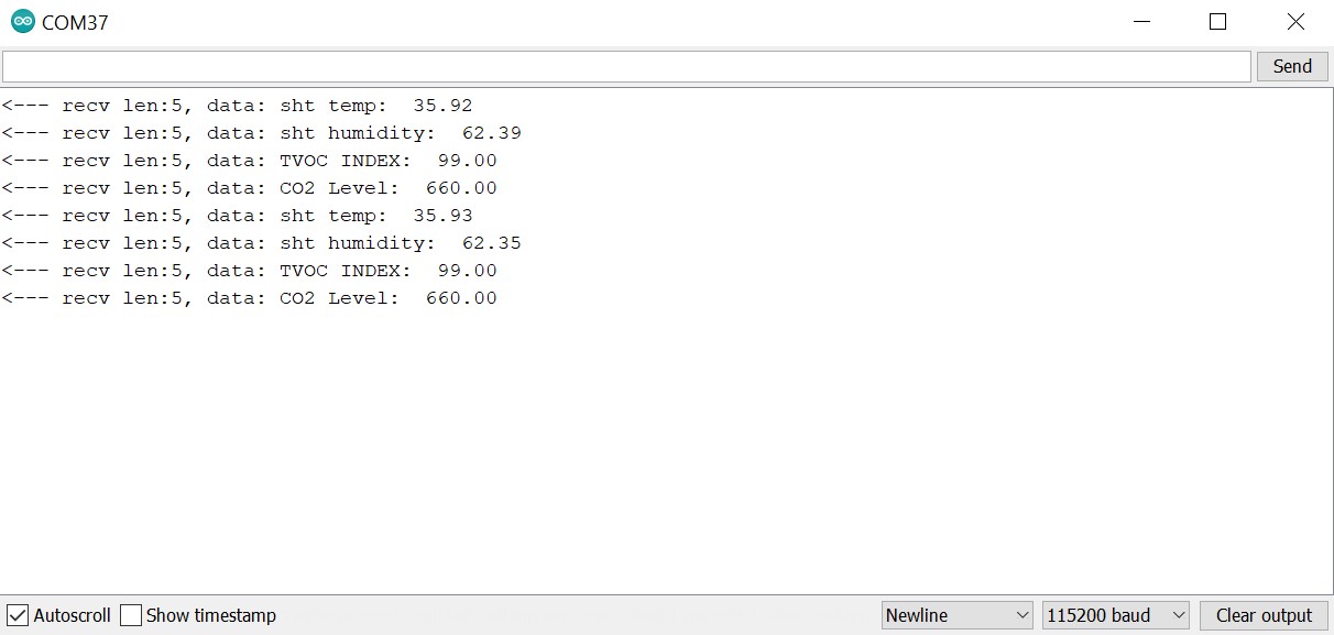
In order for the ESP32S3 to be able to read the data a library need to be installed called PacketSerial.
After the library is installed you can upload the code below to get the sensor data on the ESP32S3:
//
// Copyright (c) 2012 Christopher Baker <https://christopherbaker.net>
//
// SPDX-License-Identifier: MIT
//


#include <PacketSerial.h>

PacketSerial myPacketSerial;

#define RXD2 20
#define TXD2 19

#define PKT_TYPE_SENSOR_SCD41_CO2 0XB2
#define PKT_TYPE_SENSOR_SHT41_TEMP 0XB3
#define PKT_TYPE_SENSOR_SHT41_HUMIDITY 0XB4
#define PKT_TYPE_SENSOR_TVOC_INDEX 0XB5
#define DEBUG   0

void setup()
{
  // We begin communication with our PacketSerial object by setting the
  // communication speed in bits / second (baud).
  myPacketSerial.begin(115200);

  // If we want to receive packets, we must specify a packet handler function.
  // The packet handler is a custom function with a signature like the
  // onPacketReceived function below.

  Serial1.begin(115200, SERIAL_8N1, RXD2, TXD2);
  myPacketSerial.setStream(&Serial1);
  myPacketSerial.setPacketHandler(&onPacketReceived);
}


void loop()
{
  // Do your program-specific loop() work here as usual.

  // The PacketSerial::update() method attempts to read in any incoming serial
  // data and emits received and decoded packets via the packet handler
  // function specified by the user in the void setup() function.
  //
  // The PacketSerial::update() method should be called once per loop(). Failure
  // to call the PacketSerial::update() frequently enough may result in buffer
  // serial overflows.
  myPacketSerial.update();

  // Check for a receive buffer overflow (optional).
  if (myPacketSerial.overflow())
  {
    // Send an alert via a pin (e.g. make an overflow LED) or return a
    // user-defined packet to the sender.
    //
    // Ultimately you may need to just increase your recieve buffer via the
    // template parameters (see the README.md).
  }
}


void onPacketReceived(const uint8_t *buffer, size_t size) {


  Serial.printf("<--- recv len:%d, data: ", size);


  if (size < 1) {
    return;
  }
  //byte serbytes[] = buffer[i];
  float dataval;
  switch (buffer[0]) {
    case PKT_TYPE_SENSOR_SCD41_CO2:
      {
        memcpy(&dataval, &buffer[1], sizeof(float));
        Serial.print("CO2 Level:  ");
        Serial.println(dataval);
        break;
      }
    default:
      break;
  }
   switch (buffer[0]) {
    case PKT_TYPE_SENSOR_SHT41_TEMP:
      {
        memcpy(&dataval, &buffer[1], sizeof(float));
        Serial.print("sht temp:  ");
        Serial.println(dataval, 2);
        break;
      }
    default:
      break;
  }
   switch (buffer[0]) {
    case PKT_TYPE_SENSOR_SHT41_HUMIDITY:
      {
        memcpy(&dataval, &buffer[1], sizeof(float));
        Serial.print("sht humidity:  ");
        Serial.println(dataval, 2);
        break;
      }
    default:
      break;
  }
   switch (buffer[0]) {
    case PKT_TYPE_SENSOR_TVOC_INDEX:
      {
        memcpy(&dataval, &buffer[1], sizeof(float));
        Serial.print("TVOC INDEX:  ");
        Serial.println(dataval);
        break;
      }
    default:
      break;
  }
}
Click and open the Serial monitor and set the Baud Rate to 115200 the you will be presented the sensors data from the RP2040
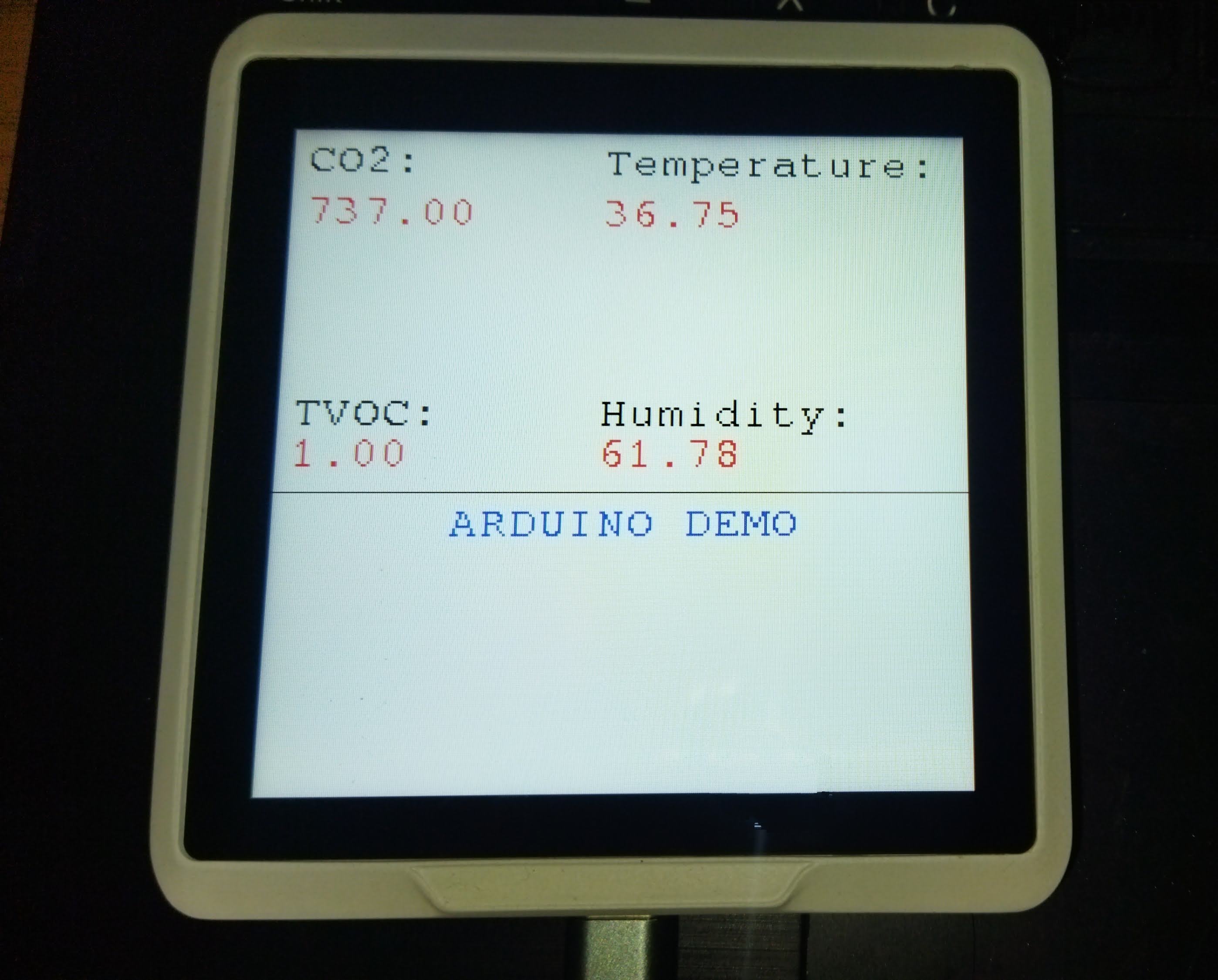
Combine two examples and display the sensors data on the screen
Open the example menu on the Arduino IDE and guide yourself to GFX library for Arduino then choose the SI_displaysensordata example and upload it.
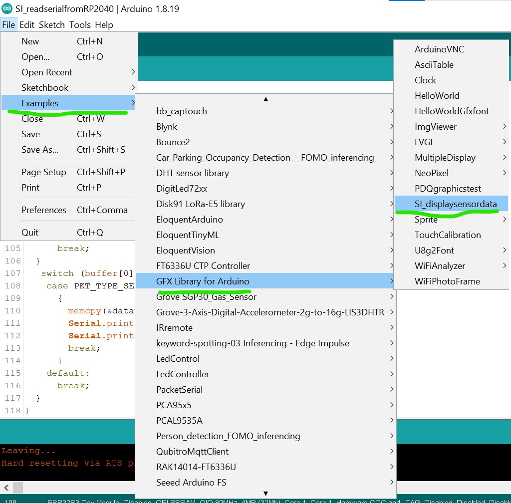
If successfully uploaded you will be presented with sensors data displayed on the screen.
Congratulation now you can develop the Sensecap Indicator using Arduino IDE!
What's More
- There is still Phase ONE for the development and what is not configured in this tutorial is the touchscreen part. I already try few arduino library for the FT6336 module but none have a successful result.
- This due to the INT Pin and RESET pin of the FT6366 module connected to the PCA9535 I2C expander and it need to configured manually in the library. I might get back to try this in the future.
- By the way, for more understanding on using the Arduino GFX library you can visit the Arduino_GFX github page
Special Thanks
Thanks to github user u4mzu4 for the SWSPI config file that support the Sensecap indicator
Thanks to LongDirtyAnimAlf for helping update the Arduino library for the SenseCAP indicator, including touchscreen support.
✨ Contributor Project
- This project is supported by the Seeed Studio Contributor Project.
- Thanks LongDirtyAnimAlf, Hendra and u4mzu4's efforts and your work will be exhibited.
Tech Support & Product Discussion
Thank you for choosing our products! We are here to provide you with different support to ensure that your experience with our products is as smooth as possible. We offer several communication channels to cater to different preferences and needs.