How to Debug Arduino Boards using SWD Interface
In this wiki, you will learn how to use SWD Interface to debug your Arduino boards via the J-Link Debug Programmer. For reference, Wio Terminal is used as the hardware to demonstrate the debugging process.
What is SWD Debugging
SWD, also known as Serial Wire Debug is a 2-pin interface (SWDIO/SWCLK) of which it's also an alternative JTAG interface that has the same JTAG protocol. SWD uses an ARM CPU standard bi-directional wire protocol, defined in the ARM Debug programmer.
Hardware Connection
Before you start, you will need the following materials:
-
Wio Terminal (or Other Arduino Boards with SWD Interface)
Wio Terminal SWD Interface
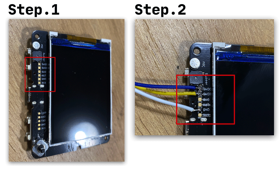
For Wio Terminal, the SWD interface pads are on the bottom of the front side of Wio Terminal (Bare PCBA without casing). There are three jumper wires that need to be led out:
- SWCLK
- SWDIO
- GND
Once the jumper wires are soldered on, we can connect them to the J-Link Debug programmer following the SWD Pin Map:
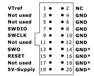
Connect as followed:
SWCLK(Wio Terminal) ->SWCLK(J-Link Debug Programmer Pin 7)SWDIO(Wio Terminal) ->SWDIO(J-Link Debug Programmer Pin 9)GND(Wio Terminal) ->GND(J-Link Debug Programmer Pin 4)
Installing J-Link GDB Server for Debugging
To debug with J-Link Debug programmer, you will need to download the J-Link GDB Server. Download and install according to your OS.
Arduino Set-up
Before launching J-Link GDB Server, you will also need to open Arduino IDE for later configurations.
1. Obtaining the Arduino Sketch ELF File Path
In the settings of Arduino IDE, make sure that the Show verbose output during compilation and upload are both ticked.
Under the Arduino sketch you want to debug, click Compile (select Wio Termianl as board), and check the log information to get the path of the .elf file location. Let's take Blink as example:
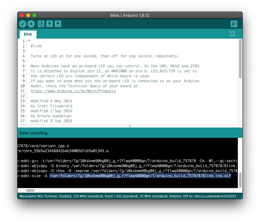
Copy this path and it will be used later for GDB.
For example, in my case:
/var/folders/7g/10kskmw90bg08j_g_r7flwq40000gn/T/arduino_build_633418/Blink.ino.elf
2. Obtain the GCC Path
Under the same sketch compile log information, you can also find the GCC path used by Arduino of which also can be used for J-Link Debug Programmer later.
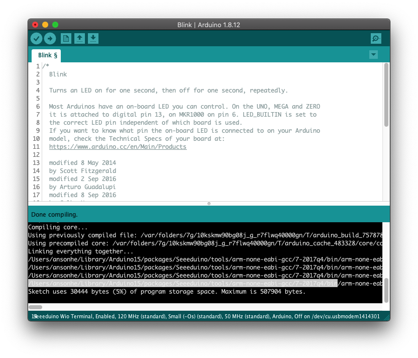
For example, in my case:
/Users/ansonhe/Library/Arduino15/packages/Seeeduino/tools/arm-none-eabi-gcc/7-2017q4/bin
Getting Started with J-Link GDB Server
Connect the J-Link Debug Programmer to the PC and also power Wio Terminal from the USB port. Launch the J-Link GDB Server, select the following settings:
- Connection to J-Link: USB
- Target Device: Cortex-M4
- Target Interface: SWD
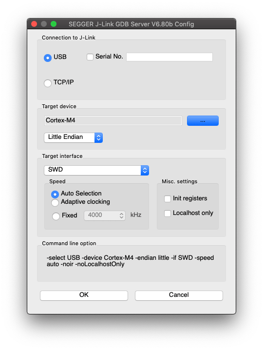
Select OK and if everything goes well you should see the following screen:
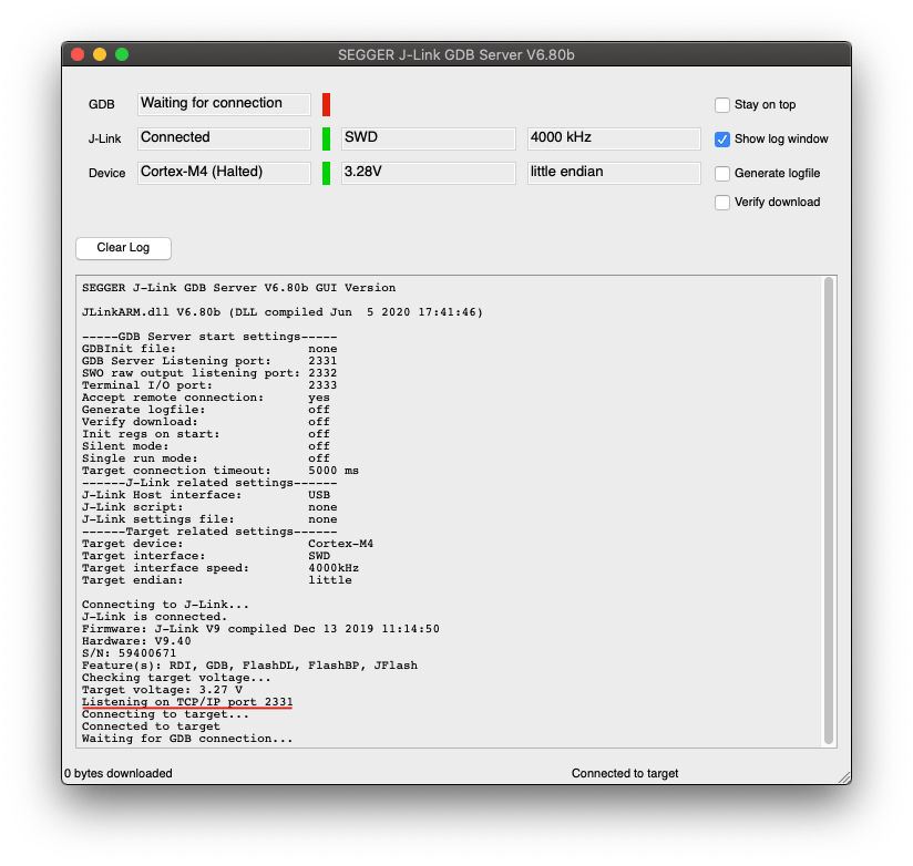
You should see that the listening port will appear and the J-Link GDB server is up and ready!
Launching a GDB Client
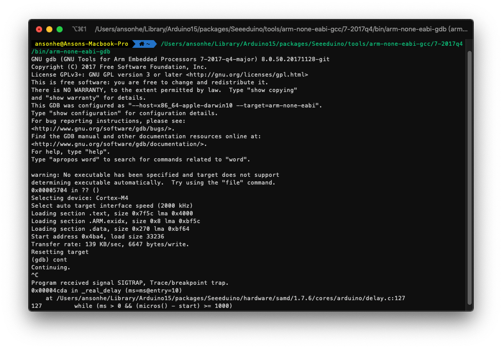
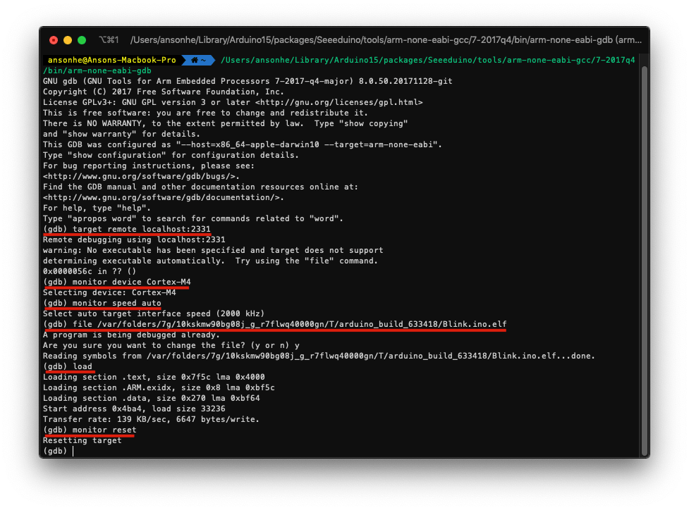
Now you can launch the GDB Client by using the path we've saved earlier from the GCC path in Arduino. Open Terminal and paste the copied path + /arm-none-eabi-gdb:
For Example: /Users/ansonhe/Library/Arduino15/packages/Seeeduino/tools/arm-none-eabi-gcc/7-2017q4/bin/arm-none-eabi-gdb
Run the following commands under gdb:
target remote localhost:2331monitor device Cortex-M4monitor speed autofile+ Arduino Sketch ELF File Path, i.e.file /var/folders/7g/10kskmw90bg08j_g_r7flwq40000gn/T/arduino_build_633418/Blink.ino.elfloadmonitor reset
Now you can use GDB to debug your Arduino Sketch!
.gdbinit Method
You can also create a .gdbinit file, copy the following and save it in the ~/ location to avoid keep repeating setting process for gbd.
target remote localhost:2331
monitor device Cortex-M4
monitor speed auto
file /var/folders/7g/10kskmw90bg08j_g_r7flwq40000gn/T/arduino_build_633418/Blink.ino.elf
load
monitor reset
Now if you just launch the GDB client and you can start debugging straight away!
Debugging
Some useful commands for GDB:
continue/contctrl+cnextbreakinfo breakcleardeletelist
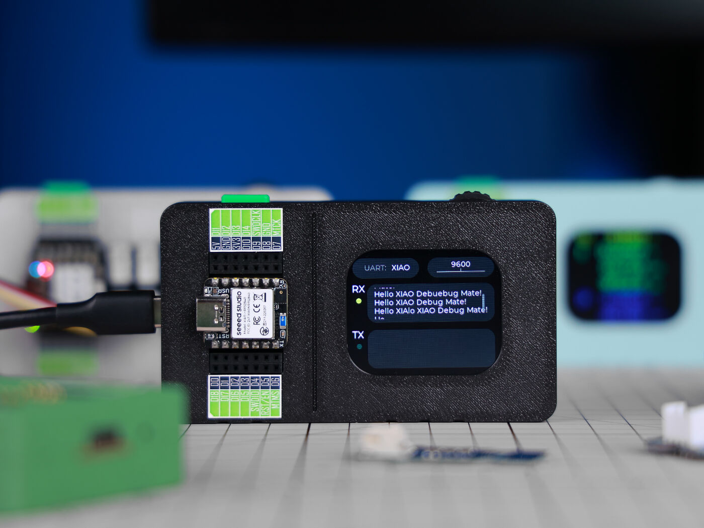
Recommended Tool: XIAO Debug Mate
For a more efficient development experience, we recommend the XIAO Debug Mate. This all-in-one development tool is designed to simplify the debugging process, offering a wire-free solution for the XIAO ecosystem while remaining a versatile utility for broader embedded projects. Powered by the ESP32-S3, it serves as a modern alternative to traditional, bulky debuggers.
Key Features:
- 3-in-1 Multi-tool: Combines a DAPLink Debugger, Serial Monitor, and Power Meter in one device.
- Visual Feedback: Features a 2.01-inch LCD screen to view real-time variable status, power curves, and serial logs without a PC.
- Plug-and-Play for XIAO: Directly plug any Seeed Studio XIAO board into it for instant debugging.
- Universal SWD Support: Can be used as a standalone SWD probe (via the 2.54mm expansion header) to debug other ARM Cortex-M microcontrollers.
Resources
FAQ
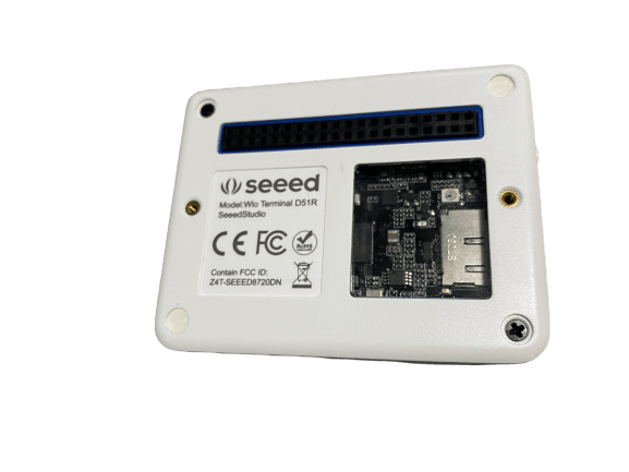
Q1. How to take off the enclosure of Wio Terminal?
A1. First, take out the 4 rubber pads of 4 corner, and you will see 2 screws that holds the Wio Terminal enclosure together. Simply unscrew them and you can take it apart.