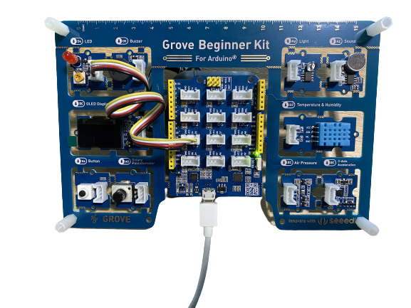
Grove Beginner Kit For Arduino
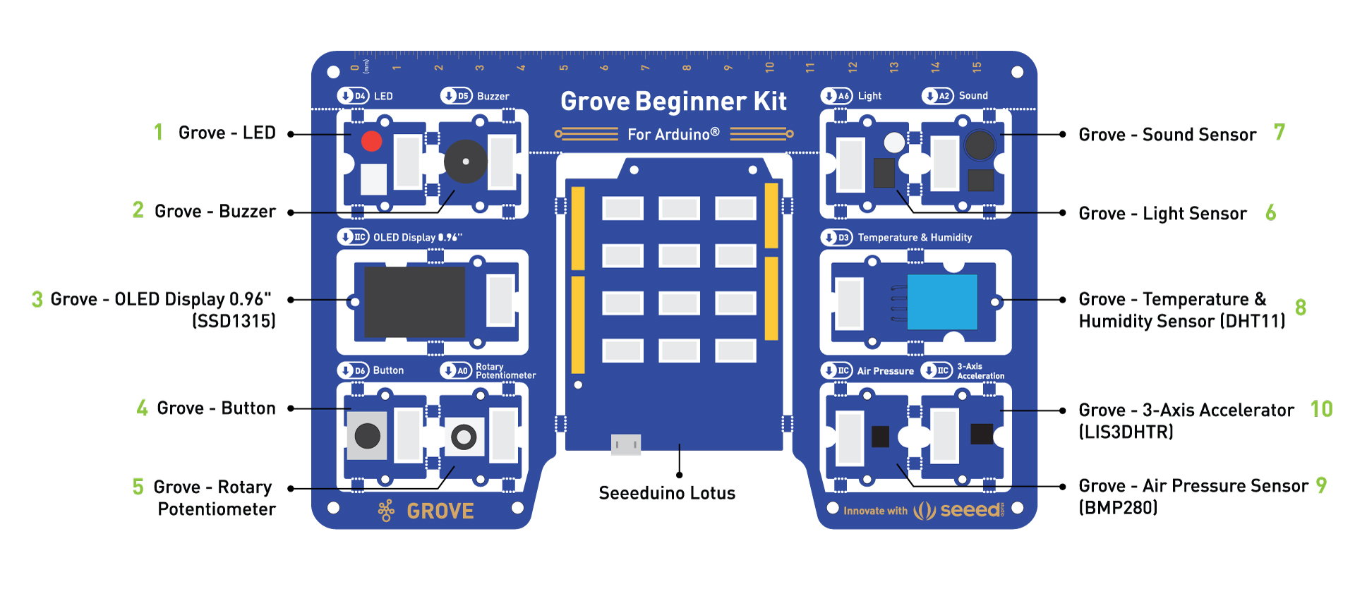
Grove Beginner Kit for Arduino is one of the best Arduino Beginner Kit for beginners. It includes one Arduino compatible Board and 10 additional Arduino sensors and all in one-piece of PCB design. All the modules have been connected to the Seeeduino through the PCB stamp holes so no Grove cables are needed to connect. Of course, you can also take the modules out and use Grove cables to connect the modules. You can build any Arduino project you like with this Grove Beginner Kit For Arduino.
Hardware Overview
Previous version (Before October 2025) ↓
New Version (After October 2025) ↓
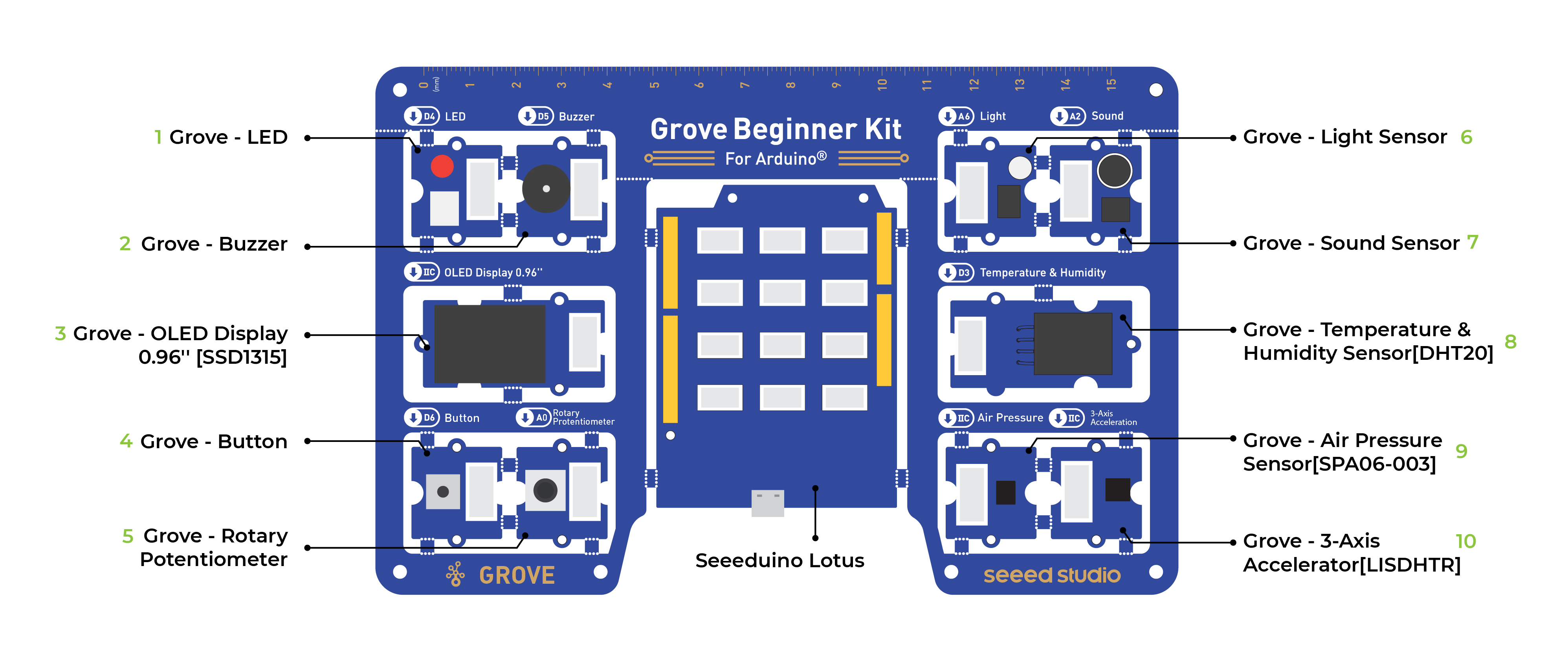
Compared to the previous version, this new release updates certain discontinued sensors. The DHT11 temperature and humidity sensor has been replaced with the DHT20 temperature and humidity sensor; the BMP280 barometric pressure sensor has been replaced with the SPA06-003 barometric pressure sensor.
Note: Dimensions - 17.69 11.64 1.88cm
- Grove - LED: Simple LED module
- Grove - Buzzer: Piezo Buzzer
- Grove - OLED Display 0.96": 128×64 dot resolution High brightness,self-emission and high contrast ratio Big screen on a compact design Low power consumption.
- Grove - Button: Momentary Push Button
- Grove - Rotary Potentiometer: Adjustable Potentiometer
- Grove - Light: Detects surrounding light intensity
- Grove - Sound: Detects surrounding sound intensity
- Grove - Temperature & Humidity Sensor: Detects surrounding temperature and humidity values. The older version used the DHT11 sensor, while versions after 2025.10 use the DHT20 sensor.
- Grove - Air Pressure Sensor: Detects surrounding atmospheric pressure
- Grove - 3-Axis Accelerator: Detects object acceleration
- Seeeduino Lotus: Arduino Compatible Board with Grove Ports
Note: By default, Grove modules are connected to Seeeduino via PCB stamp holes. This means you don't need to use Grove cables to connect if not broken out. The default pins are as follow:
| Modules | Interface | Pins/Address |
|---|---|---|
| LED | Digital | D4 |
| Buzzer | Digital | D5 |
| OLED Display 0.96" | I2C | I2C, 0x78(default) |
| Button | Digital | D6 |
| Rotary Potentiometer | Analog | A0 |
| Light | Analog | A6 |
| Sound | Analog | A2 |
| Temperature & Humidity Sensor | Digital | D3 |
| Air Pressure Sensor | I2C | I2C, 0x77(default) / 0x76(optional) |
| 3-Axis Accelerator | I2C | I2C, 0x19(default) |
Breakout Instruction
Attention: Please be careful not to cut your hands when using a knife
If you prefer to use the modules in elsewhere then you can simply follow the procedures to break the modules out!
Step 1
Use a knife or a sharp object to cut at the stamp holes that connect the sensors together
Step 2
Shake the modules up and down and it should come out quite easily!
Part List
| Modules | Quantity |
|---|---|
| Sensors | |
| Temperature & Humidity Sensors | x1 |
| 3-Axis Accelerometers | x1 |
| Air Pressure | x1 |
| Light Sensor | x1 |
| Sound Sensor | x1 |
| Input Modules | |
| Rotary Potentiometer | x1 |
| Button | x1 |
| Output Modules | |
| LED | x1 |
| Buzzer | x1 |
| Display Module | |
| OLED Display | x1 |
| Grove Cables | x6 |
| Micro USB Cable (previous version) / USB Cable (new version dated October 2025) | x1 |
Learning Objectives
- Basics of Open Source Hardware Systems.
- Basic Arduino Programming.
- Communication principles and methods for sensors.
- Hands-on implementation of Open Source Hardware projects.
Plug and Play Unboxing Demo
The Grove Beginner Kit has a plug and plays unboxing demo, where you first plug in the power to the board, you get the chance to experience all the sensors in one go! Use the button and rotary potentiometer to experience each sensor demo!

- Scroll -> Rotating Rotary Potentiometer
- Select -> Short Press Button
- Exit Current Demo -> Long Press Button
Buzzer and LED module are used for key prompt.
How to Get Started With Arduino
Install the Arduino IDE
- Arduino IDE is an integrated development environment for Arduino, which is used for single-chip microcomputer software programming, downloading, testing and so on.
- Download and Install Arduino IDE for your desired operating system here.

Install the USB driver
-
Arduino connects to the PC via a USB cable. The USB driver depends on the type of USB chip you're using on your Arduino. Note: USB chips are usually printed on the back of the development board.
- Download the CP2102 USB Driver. Note: Download according to your OS.
- After the driver installation is completed, connect Arduino to the USB port of PC with a USB cable.
- For Windows users: You can see it in
My Computer->Properties->Hardware->Device Management. ACOMwill appear. - For Mac OS users: You can navigate to
on the top left corner, and chooseAbout this Mac->System Report...->USB. A CP2102 USB Driver should appear.
- For Windows users: You can see it in
- If the driver is not installed, or if the driver is installed incorrectly (not matching the chip model), it will appear as an "unknown device" in the device manager. At this point, the driver should be reinstalled.
Start the Arduino IDE
1.Open the Arduino IDE on your PC.
2.Click on Tools -> Board-> Arduino AVR Boards-> Arduino Uno to select the correct Development Board Model. Select Arduino Uno as Board.

3.Click Tools -> Port to select the correct Port (the Serial Port showed in Device Manager in the previous step). In this case, COM11 is selected. For Mac OS users, it should be /dev/cu.SLAB_USBtoUART.

4.Create a new Arduino file and name it Hello.ino, then copy the following code into it:
void setup() {
  Serial.begin(9600); // initializes the serial port with a baud rate of 9600
}
void loop() {
  Serial.println("hello, world"); // prints a string to a serial port
  delay(1000); //delay of 1 second
}
5.In the upper left corner of the Arduino IDE, there are two buttons, Verify and Upload. First, press the Verify button(✓) to compile. After the compilation is successful, press the upload button(→).

6.Navigate to Tools -> Serial Monitor, or click the Serial Monitor in the upper right corner(Magnifier Symbol), you can see the program running results:

Note: If you installed the portable Arduino IDE from our USB Drive, you can find all the module demos in the Files -> Sketch Book, as well as all the module libraries, are pre-installed with Arduino IDE!

Note: All modules are pre-wired on a single circuit board, so no cables and soldering are needed. However, if you break out the modules and want to connect them with Grove cables, please kindly check the Breakout Guide.
Lesson Guide
Lesson 1: Blinking with the LED
We have completed the output "Hello world" program. Now let's learn how to light the LED module. We know the three basic components of a control system: Input, Control, and Output. But lighting up LED uses only the output, not the input. Seeeduino is the control unit, the LED module is the output unit and the output signal is a digital signal.
Background Information:
- What is Digital Signal
Digital signal: Digital signal refers to the value of the amplitude is discrete, the amplitude is limited to a finite number of values. In our controller, the digital signal has two states: LOW(0V) for 0; HIGH(5V) for 1. So sending a HIGH signal to LED can light it up.

Components Involved
- Seeeduino Lotus
- Grove LED
- Grove Cable(If Broken out)

Hardware connection
- Module connection
- Default connection by PCB stamp hole.
- Connect the Seeeduino to the computer through the USB cable.
-Software Code
- Open Arduino IDE.
- Copy the following code, click Verify to check for syntax errors. Verify that there are no errors, and you can upload the code.
//LED Blink
//The LED will turn on for one second and then turn off for one second
int ledPin = 4;
void setup() {
    pinMode(ledPin, OUTPUT);
}
void loop() {
    digitalWrite(ledPin, HIGH);
    delay(1000);
    digitalWrite(ledPin, LOW);
    delay(1000);
}
Code Analysis
setup(){
}
The setup() function is called when a sketch starts. Use it to initialize variables, pin modes, start using libraries, etc. The setup() function will only run once, after each powerup or reset of the Arduino board.
loop(){
}
After creating a setup() function, which initializes and sets the initial values, the loop() function does precisely what its name suggests, and loops consecutively, allowing your program to change and respond. Use it to actively control the Arduino board.
int ledPin = 4;
Description:
Converts a value to the int data type.
Syntax:
int(x) or (int)x (C-style type conversion)
Parameters:
x: a value. Allowed data types: any type.
Assigned an int type 4 to variable named ledPin.
pinMode(ledPin, OUTPUT);
Description:
Configures the specified pin to behave either as an input or an output. See the Digital Pins page for details on the functionality of the pins.
As of Arduino 1.0.1, it is possible to enable the internal pull-up resistors with the mode INPUT_PULLUP. Additionally, the INPUT mode explicitly disables the internal pullups.
Syntax:
pinMode(pin, mode)
Parameters:
pin: the Arduino pin number to set the mode of.
mode: INPUT, OUTPUT, or INPUT_PULLUP.
Setting ledPin to the output mode.
digitalWrite(ledPin, HIGH);
Description:
Write a HIGH or a LOW value to a digital pin.
If the pin has been configured as an OUTPUT with pinMode(), its voltage will be set to the corresponding value: 5V (or 3.3V on 3.3V boards) for HIGH, 0V (ground) for LOW.
If the pin is configured as an INPUT, digitalWrite() will enable (HIGH) or disable (LOW) the internal pullup on the input pin. It is recommended to set the pinMode() to INPUT_PULLUP to enable the internal pull-up resistor. See the Digital Pins tutorial for more information.
If you do not set the pinMode() to OUTPUT, and connect an LED to a pin, when calling digitalWrite(HIGH), the LED may appear dim. Without explicitly setting pinMode(), digitalWrite() will have enabled the internal pull-up resistor, which acts as a large current-limiting resistor.
Syntax:
digitalWrite(pin, value)
Parameters:
pin: the Arduino pin number.
value: HIGH or LOW.
When we set the ledPin as output, HIGH means sending high level to the pin, LED turns on.
digitalWrite(ledPin, LOW);
When we set the led as output, low stands for sending low level to the pin, LED turns off.
delay(1000);
Description:
Pauses the program for the amount of time (in milliseconds) specified as a parameter. (There are 1000 milliseconds in a second.)
Syntax:
delay(ms)
Parameters:
ms: the number of milliseconds to pause. Allowed data types: unsigned long.
Delay the program by 1000ms(1s).
Demo Effect and Serial Print Result:
The LED module will be 1 second on and 1 second off.
LED Brightness Adjustment:
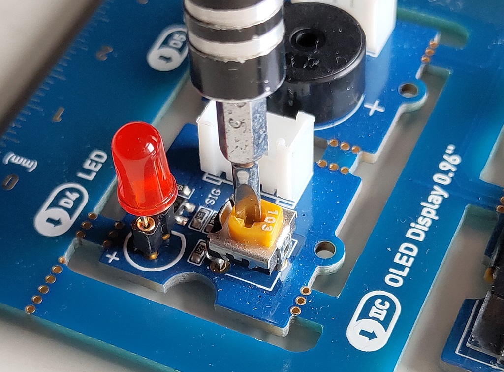
On the Grove LED module, there is a variable resistor that can be adjusted using a screw driver. Twist it to make the LED light up brighter!
Breakout Guide
If modules are broken out from the board. Use a Grove cable to connect the Grove LED to Seeeduino Lotus's digital interface D4.
Lesson 2: Pressing Button to Light Up LED
The first thing we need to know is that the input of the button is a digital signal, and there are only two states, 0 or 1, so we can control the output based on those two states.
- Practice: Use button to turn ON and OFF the LED module
Components Involved
- Seeeduino Lotus
- Grove LED
- Grove Button
- Grove Cables(If broken out)

Hardware connection
-
Module connection:
- Default connection by PCB stamp hole.
-
The Seeeduino is then connected to the computer via a USB cable.
-
Hardware analysis:
- Input: Button
- Control: Seeeduino
- Output: LED module
Both the sensor and the LED use digital signals, so they should be connected to digital interfaces.
- Software code:
- Open Arduino IDE.
- Copy the following code, click Verify to check for syntax errors. Verify that there are no errors, and you can upload the code.
//Button to turn ON/OFF LED
//Constants won't change. They're used here to set pin numbers:
const int buttonPin = 6;     // the number of the pushbutton pin
const int ledPin =  4;      // the number of the LED pin

// variables will change:
int buttonState = 0;         // variable for reading the pushbutton status

void setup() {
  // initialize the LED pin as an output:
  pinMode(ledPin, OUTPUT);
  // initialize the pushbutton pin as an input:
  pinMode(buttonPin, INPUT);
}

void loop() {
  // read the state of the pushbutton value:
  buttonState = digitalRead(buttonPin);

  // check if the pushbutton is pressed. If it is, the buttonState is HIGH:
  if (buttonState == HIGH) {
    // turn LED on:
    digitalWrite(ledPin, HIGH);
  } else {
    // turn LED off:
    digitalWrite(ledPin, LOW);
  }
}
Code Analysis
pinMode(ledPin, OUTPUT);
Define LED as the output unit.
pinMode(buttonPin, INPUT);
Define button as the input unit.
buttonState = digitalRead(buttonPin);
Description:
Reads the value from a specified digital pin, either HIGH or LOW.
Syntax:
digitalRead(pin)
Parameters:
pin: the Arduino pin number you want to read
This function is used to read the states of digital pins, either HIGH or LOW. When the button is pressed, the state is HIGH, otherwise is LOW.
  if (buttonState == HIGH) {
    digitalWrite(ledPin, HIGH);
  } else {
    digitalWrite(ledPin, LOW);
  }
}
Description:
The if…else allows greater control over the flow of code than the basic if statement, by allowing multiple tests to be grouped. An else clause (if at all exists) will be executed if the condition in the if statement results in false. The else can proceed another if test, so that multiple, mutually exclusive tests can be run at the same time.
Each test will proceed to the next one until a true test is encountered. When a true test is found, its associated block of code is run, and the program then skips to the line following the entire if/else construction. If no test proves to be true, the default else block is executed, if one is present, and sets the default behaviour.
Note that an else if block may be used with or without a terminating else block and vice versa. An unlimited number of such else if branches are allowed.
Syntax:
if (condition1) {
  // do Thing A
}
else if (condition2) {
  // do Thing B
}
else {
  // do Thing C
}
The usage of the statement is: if the logical expression in parentheses is true, execute the statement in curly braces after if, if not, execute the statement in curly braces after the else. If the state of the button is high, the LED pin outputs a high level and turn the LED on, else turn LED off.
Demo Effect and Serial Print Result:
Pressing the button will turn the LED module on.
Breakout Guide
Use a Grove cable to connect the Grove LED to Seeeduino Lotus's digital interface D4. Connect the Grove Button to digital interface D6.
Lesson 3: Controlling the Frequency of the Blink
In the last section, we studied that button only has two states, ON/OFF state corresponding 0V and 5V, but in practice, we often counter the need for many states, not just 0V and 5V. Then you need to use Analog Signal! Rotary Potentiometer is a classic example that uses an analog signal.
Background Information:
- What is Analog Signal
Analog signals: Signals vary continuously in time and value, and the amplitude, frequency, or phase of the signal changes continuously at any time, such as the current broadcast sound signal, or image signal, etc. The analog signal has sine wave and triangle wave and so on. The analog pins of your microcontroller can have between 0V and 5V is mapped to a range between 0 and 1023 where 1023 is mapped as 5V and 512 is mapped as 2.5v and etc.

Components Involved
- Seeeduino Lotus
- Grove LED
- Grove Rotary Switch
- Grove Cables(If broken out)

Hardware connection
-
Module connection:
- Default connection by PCB stamp hole.
-
The Seeeduino is then connected to the computer via a USB cable.
-
Hardware analysis:
- Input: Rotary Potentiometer
- Control: Seeeduino Lotus
- Output: LED module
The input is an analog signal, so it is connected to the analog signal interface, the LED module is connected to the digital signal interface.
Software
- Open Arduino IDE.
- Copy the following code, click Verify to check for syntax errors. Verify that there are no errors, and you can upload the code.
//Rotary controls LED
int rotaryPin = A0;    // select the input pin for the rotary
int ledPin = 4;      // select the pin for the LED
int rotaryValue = 0;  // variable to store the value coming from the rotary

void setup() {
  // declare the ledPin as an OUTPUT:
  pinMode(ledPin, OUTPUT);
  pinMode(rotaryPin, INPUT);
}

void loop() {
  // read the value from the sensor:
  rotaryValue = analogRead(rotaryPin);
  // turn the ledPin on
  digitalWrite(ledPin, HIGH);
  // stop the program for <sensorValue> milliseconds:
  delay(rotaryValue);
  // turn the ledPin off:
  digitalWrite(ledPin, LOW);
  // stop the program for for <sensorValue> milliseconds:
  delay(rotaryValue);
}
Code Analysis
int rotaryPin = A0;    // select the input pin for the rotary
int ledPin = 4;      // select the pin for the LED
Description:
You may find that we define rotatePin and ledPin in different ways. This is because Rotary Potentiometer generates an analog signal, and the LED is controlled by a digital signal.
To define for Analog Pin, use A + the number of the Pin (For Example here A0).
To define for Digital Pin, use just the number of the pin (For Example here 4).
rotaryValue = analogRead(rotaryPin);
Description:
Reads the value from the specified analog pin. Arduino boards contain a multichannel, 10-bit analog to digital converter. This means that it will map input voltages between 0 and the operating voltage(5V or 3.3V) into integer values between 0 and 1023. On an Arduino UNO, for example, this yields a resolution between readings of: 5 volts / 1024 units or, 0.0049 volts (4.9 mV) per unit.
Syntax:
analogRead(pin)
Parameters:
pin: the name of the analog input pin to read from (A0 to A5 on most boards).
Returns: The analog reading on the pin. Although it is limited to the resolution of the analog to digital converter (0-1023 for 10 bits or 0-4095 for 12 bits). Data type: int.
This function is used to read the value of Analog pins(the rotary sensor position), the range of values is: 0 ~ 1023.
delay(rotaryValue);
Delay function, The millisecond duration of the delay is the value in parentheses. Because the value is the value of the analog signal of the knob pin being read, so the delay time can be controlled by the knob.
Demo Effect and Serial Print Result:
Turning the Potentiometer will change the frequency of LED flickering.
Breakout Guide
Use a Grove cable to connect LED to Seeeduino Lotus's digital interface D4, and a Grove cable to connect the Grove Rotary Switch to analog signal interface A0.
Lesson 4: Making the Buzzer go BEEP
Just like the LED module, Buzzer is also an output module, instead of lighting up it produces a beep sound. This can be used for many situations for indication purposes.Let's learn how to generate sound using the buzzer!
Background Information:
- What is the difference between Active and Passive Buzzer
There are two types of buzzers, one is active and the other is passive. Both active and passive buzzers are used to make sound to electronics.
The active buzzer has an internal oscillation source that makes the buzzer sound whenever power is applied. Active buzzers are widely used in computers, printers, copiers, alarms, electronic toys, car electronics, telephones, timers and other electronic product sounding devices.
A passive buzzer has no internal source of oscillation and needs to be driven by a square wave and a different frequency. It acts like an electromagnetic speaker, and the changing input signal produces sound, rather than a tone automatically.
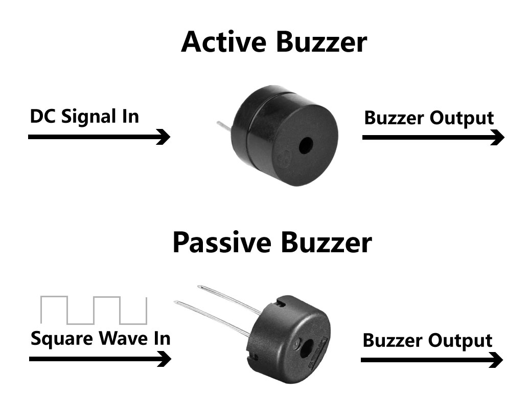
In this kit, the Grove-Buzzer is a passive buzzer so that it needs an AC signal to control it. This then leads to the next question, how to generate Square Wave(AC signals) with Arduino! Well, an easy way is to use PWM.
- What is PWM
Pulse Width Modulation, or PWM, is a technique for getting analog results with digital means. Digital control is used to create a square wave, a signal switched between on and off. This on-off pattern can simulate voltages in between full on (5 Volts) and off (0 Volts) by changing the portion of the time the signal spends on versus the time that the signal spends off. The duration of "on time" is called the pulse width. To get varying analog values, you change, or modulate, that pulse width. If you repeat this on-off pattern fast enough, the result is as if the signal is a steady voltage between 0 and 5v as a AC signal. Reference: Arduino. This PWM signal can then be used to control the passive buzzer with ease.
To generate PWM signals in Arduino, you can use analogWrite(), in contrast to using digitalWrite() to generate DC signals.
There are six digital pins on your Seeeduino that are marked with the symbol “~”, which means they can send out a PWM signal : 3,5,6,9,10,11. They are celled PWM pins.
Components Involved
- Seeeduino Lotus
- Grove Buzzer
- Grove Cable(If Broken out)

Hardware connection
- Module connection
- Default connection by PCB stamp hole.
- Connect the Seeeduino to the computer through the USB cable.
Software Code
- Open Arduino IDE.
- Copy the following code, click Verify to check for syntax errors. Verify that there are no errors, and you can upload the code.
int BuzzerPin = 5;

void setup() {
  pinMode(BuzzerPin, OUTPUT);
}

void loop() {
  analogWrite(BuzzerPin, 128);
  delay(1000);
  analogWrite(BuzzerPin, 0);
  delay(0);
}
Code Analysis
analogWrite(BuzzerPin, 128);
Description:
Writes an analog value (PWM wave) to a pin. Can be used to light a LED at varying brightnesses or drive a motor at various speeds. After a call to analogWrite(), the pin will generate a steady rectangular wave of the specified duty cycle until the next call to analogWrite() (or a call to digitalRead() or digitalWrite()) on the same pin.
Syntax:
analogWrite(pin, value)
Parameters:
pin: the Arduino pin to write to. Allowed data types: int.
value: the duty cycle: between 0 (always off) and 255 (always on). Allowed data types: int.
Writes an analog value (PWM wave) to the Buzzer.
Demo Effect and Serial Print Result:
The Buzzer beeps.
Breakout Guide
Use a Grove cable to connect the Grove Buzzer to Seeeduino Lotus's digital interface D5.
PWM Usage
Now that we have learned the use of PWM, in addition to using PWM to control the passive buzzer, we can also use PWM to control the speed of the motor and the brightness of the LED lights and etc.
As the diagram indicates below, use analogWrite() to generate PWM waves, the higher the percentage of Duty Cycle, the brighter the LED.
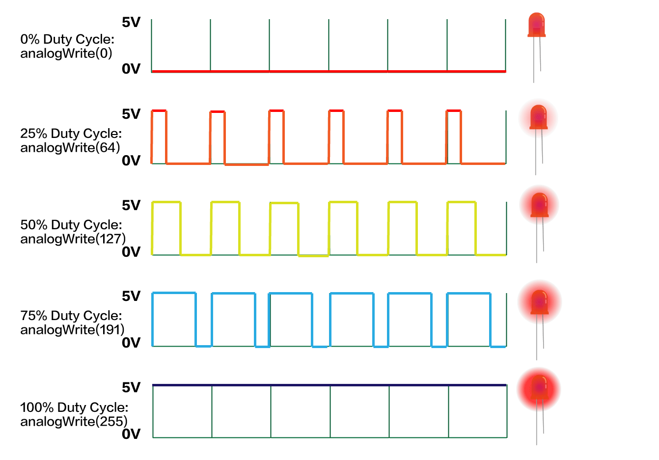
However, the LED Module on the Grove Beginner Kit cannot be directly controlled by PWM, because the LED module is connected to D4, and as mentioned above, the PWM pins are 3, 5, 6, 9, 10, 11, and pin 4 is not a PWM pin. If you want to control the LED with PWM, you need to pull it down and use the Grove cable to connect to the Grove port with PWM function.
For example, let's connect Grove-LED to D3 using a Grove cable:
!!!Note D3 is also inter-connected to the Grove-Temperature & Humidity Sensor, and therefore this example cannot be used with Grove-Temperature & Humidity Sensor together.
int LED = 3; // Cable connection from LED to D3
int Potentiometer = A0;

void setup() {
  pinMode(LED, OUTPUT);
  pinMode(Potentiometer, INPUT);
}

void loop() {
  int potentioValue, Value;
  potentioValue = analogRead(Potentiometer);
  Value = map(potentioValue, 0, 1023, 0, 255); //Mapping potentiometer value to PWM signal value
  analogWrite(LED, Value);
}
Compile and upload the code you should be able to twist and adjust the LED brightness using PWM signals!
Code Analysis
Value = map(potentioValue, 0, 1023, 0, 255);
Description:
Re-maps a number from one range to another. That is, a value of fromLow would get mapped to toLow, a value of fromHigh to toHigh, values in-between to values in-between, etc.
Does not constrain values to within the range, because out-of-range values are sometimes intended and useful. The constrain() function may be used either before or after this function, if limits to the ranges are desired.
Note that the "lower bounds" of either range may be larger or smaller than the "upper bounds" so the map() function may be used to reverse a range of numbers, for example
y = map(x, 1, 50, 50, 1);
The function also handles negative numbers well, so that this example
y = map(x, 1, 50, 50, -100);
is also valid and works well.
The map() function uses integer math so will not generate fractions, when the math might indicate that it should do so. Fractional remainders are truncated and are not rounded or averaged.
Syntax:
map(value, fromLow, fromHigh, toLow, toHigh)
Parameters:
value: the number to map.
fromLow: the lower bound of the value’s current range.
fromHigh: the upper bound of the value’s current range.
toLow: the lower bound of the value’s target range.
toHigh: the upper bound of the value’s target range.
Mapping Potentiometer sensor analog signal(0 to 1023)to the loudness of Light(0 to 255).
Demo Effect and Serial Print Result:
Adjust the potentiometer to adjust the LED brightness.
All in all, when you want to use the PWM function, make sure to select those pins with a "~" symbol in front of their names.
Lesson 5: Making an Light Induct LED
The light sensor contains a photosensitive resistor to measure the intensity of light. The resistance of the photosensitive resistor decreases with the increase of light intensity. The LED will light up if the surrounding is dark, and stays off if the surrounding is bright.
In the following sections, we will use Serial Monitor to observe results from our sensors so here comes the brief introduction!
Background Information:
- What is Serial Monitor
Serial Monitor is a useful tool to observe results on Arduino, it can be very useful in terms of printing results from the sensors or debugging in general. You can also send data back to the controller via the serial monitor to do certain tasks! Note: Make sure the Serial data transfer match with the code.

You can open the Serial Monitor by clicking Tools -> Serial Monitor.

Components Involved
- Seeeduino Lotus
- Grove LED
- Grove Light Sensor
- Grove Cable(If broken out)

Hardware connection
-
Module connection:
- Default connection by PCB stamp hole.
-
The Seeeduino is then connected to the computer via a USB cable.
-
Hardware analysis:
- Input: Light Sensor
- Control: Seeeduino Lotus
- Output: LED module
Software Code
- Open Arduino IDE.
- Copy the following code, click Verify to check for syntax errors. Verify that there are no errors, and you can upload the code.
// Light Switch
int sensorpin = A6; // Analog input pin that the sensor is attached to
int ledPin = 4;    // LED port
int sensorValue = 0;        // value read from the port
int outputValue = 0;        // value output to the PWM (analog out)

void setup() {
  pinMode(ledPin,OUTPUT);
  pinMode(sensorpin, INPUT);
  Serial.begin(9600);
}

void loop() {
  // read the analog in value:
  sensorValue = analogRead(sensorpin);

  Serial.println(sensorValue);

  if (sensorValue < 200) {
    digitalWrite(ledPin, HIGH);
  }
  else {
    digitalWrite(ledPin, LOW);
  }

  delay(200);
}
You can also see the light intensity readings from the Serial Monitor, navigate to Tools -> Serial Monitor.
Code Analysis
Serial.begin(9600);
Description:
Sets the data rate in bits per second (baud) for serial data transmission. For communicating with Serial Monitor, make sure to use one of the baud rates listed in the menu at the bottom right corner of its screen. You can, however, specify other rates - for example, to communicate over pins 0 and 1 with a component that requires a particular baud rate.
An optional second argument configures the data, parity, and stop bits. The default is 8 data bits, no parity, one stop bit.
The software running on the computer communicates with the development board, and the baud rate is 9600.
Syntax:
Serial.begin(speed)
Parameters:
speed: Speed of Serial communication. i.e 9600, 115200 and etc.
Set the Serial baud rate to 9600.
Serial.println(sensorValue);
Description:
Prints data to the serial port as human-readable ASCII text followed by a carriage return character (ASCII 13, or '\r') and a newline character (ASCII 10, or '\n'). This command takes the same forms as Serial.print().
Syntax:
Serial.println(val) or Serial.println(val, format)
Parameters:
val: the value to print. Allowed data types: any data type.
format: specifies the number base (for integral data types) or the number of decimal places (for floating point types).
Serial port print the Light sensor’s value. So you open the serial monitor on the IDE interface, and you see the value of the output sensor.
Demo Effect and Serial Print Result:
The LED module will light up if it's dark and stay off if it's bright.
Breakout Guide
Use Grove Cable to connect the Grove LED to Seeeduino Lotus's digital signal interface D4,connect the Grove Light Sensor to Seeeduino Lotus's analog signal interface A6.
Lesson 6: Sound Sensitive LED Light
The sound sensor can detect the sound intensity of the environment, and its output is also simulated. I'm sure you've all been exposed to the sound control lights, but now we can do one ourselves, and with the basics, this experiment will be easy for you. Here used Serial Plotter to visualize results.
Background Information:
- What is Serial Plotter
Serial Plotter is similar to Serial Monitor, allowing you to natively graph serial data from your Arduino to your computer in real-time. This is very useful when data needs to be visualized.

You can open the Serial Plotter by clicking Tools -> Serial Plotter.

- Practice: The LED lights light up when the sound is made. When there is no sound and it is very quiet, the LED lights go off.
Components Involved
- Seeeduino Lotus
- Grove LED
- Grove Sound Sensor
- Grove cable(If broken out)

Hardware connection
- Module connection:
- Default connection by PCB stamp hole.
- The Seeeduino is then connected to the computer via a USB cable.
Software Code
- Open Arduino IDE.
- Copy the following code, click Verify to check for syntax errors. Verify that there are no errors, and you can upload the code.
//Sound Control Light
int soundPin = A2; // Analog sound sensor is to be attached to analog
int ledPin = 4; // Digital LED is to be attached to digital
void setup() {
  pinMode(ledPin, OUTPUT);
  pinMode(soundPin, INPUT);
  Serial.begin(9600);
}
void loop(){
  int soundState = analogRead(soundPin); // Read sound sensor’s value
  Serial.println(soundState);
  // if the sound sensor’s value is greater than 400, the light will be on.
  //Otherwise, the light will be turned off
  if (soundState > 400) {
    digitalWrite(ledPin, HIGH);
    delay(100);
  }else{
    digitalWrite(ledPin, LOW);
  }
}
You can also see the light intensity readings from the Serial Plotter, navigate to Tools -> Serial Plotter.
Note: You can also adjust the value according to your surrounding light intensity.
Code Analysis
Serial.begin(9600);
The software running on the computer communicates with the development board, and the baud rate is 9600.
Serial.print(" ");
This function is used to output data from the serial port, the output is what is contained in the double quotation marks.
Serial.println( );
This statement is similar to the one above, except that serial.println has a newline return.
Serial.println(soundState);
Serial port print the sound sensor’s value. So you open the serial monitor on the IDE interface, and you see the value of the output sensor.
Demo Effect and Serial Print Result:
The LED module will light up if the surrounding is loud enough.
Breakout Guide
Use Grove cables to connect the Grove LED to Seeeduino Lotus's digital signal interface D4, Connect the Grove Sound Sensor to Seeeduino Lotus's analog signal interface A2.
Lesson 7: Displaying Data on OLED
OLED Display can be used for many situations, where you could use it to visualize sensor readings!
Background Information:
- What is Arduino Libraries
The Arduino environment can be extended through the use of libraries, just like most other programming platforms. Libraries provide extra functionalities for use in sketches, i.e. working with specific hardware or manipulating data. To use a library in a sketch, select it from Sketch ->Include Library.

For more information, please also visit How to install Arduino Libraries.
Components Involved
- Seeeduino Lotus
- Grove OLED
- Grove cable(If broken out)

Hardware connection
- Module connection:
- Default connection by PCB stamp hole.
- The Seeeduino is then connected to the computer via a USB cable.
Software Code
- Open Arduino IDE.
- Install the U8g2 library: Navigate to Sketch -> Include Library -> Manage Libraries... and Search for the keyword "U8g2" in the Library Manager. It's the u8g2 library by oliver, and click then install.

- Copy the following code, click Verify to check for syntax errors. Verify that there are no errors, and you can upload the code.
#include <Arduino.h>
#include <U8x8lib.h>

 U8X8_SSD1306_128X64_NONAME_HW_I2C u8x8(/* reset=*/ U8X8_PIN_NONE);

// U8X8_SSD1306_128X64_NONAME_SW_I2C u8x8(/* clock=*/ SCL, /* data=*/ SDA, /* reset=*/ U8X8_PIN_NONE);   // OLEDs without Reset of the Display

void setup(void) {
  //u8x8.setBusClock(100000);  // If you breakout other modules, please enable this line
  u8x8.begin();
  u8x8.setFlipMode(1);
}

void loop(void) {
  u8x8.setFont(u8x8_font_chroma48medium8_r);
  u8x8.setCursor(0, 0);
  u8x8.print("Hello World!");
}
!!!Attention If you breakout all the modules and use the Grove OLED separately, you may find it won't work with this code. If you encounter such a problem, please refer to the end of this section: Breakout Guide.
- Code analysis
#include <>
Description:
#include is used to include outside libraries in your sketch. This gives the programmer access to a large group of standard C libraries (groups of pre-made functions), and also libraries written especially for Arduino.
Note that #include, similar to #define, has no semicolon terminator, and the compiler will yield cryptic error messages if you add one.
#include <U8x8lib.h>
#include is an instruction that introduces a header file. Here we use the U8x8lib.h library.
U8X8_SSD1306_128X64_NONAME_HW_I2C u8x8(/* reset=*/ U8X8_PIN_NONE);
Note
If you break out other modules and only use OLED, you have to software I2C:
// U8X8_SSD1306_128X64_NONAME_HW_I2C u8x8(/* reset=*/ U8X8_PIN_NONE);

U8X8_SSD1306_128X64_NONAME_SW_I2C u8x8(/* clock=*/ SCL, /* data=*/ SDA, /* reset=*/ U8X8_PIN_NONE);
Description:
Once the object is declared, you can use functions from the library.
u8x8.begin();
Description:
Simplified setup procedure of the display for the Arduino environment. See the setup guide for the selection of a suitable U8g2 constructor.
Syntax:
u8x8.begin()
Initialize the u8g2 library
u8x8.setFlipMode(1);
Description:
Some displays support a 180-degree rotation of the internal frame buffer. This hardware feature can be controlled with this procedure. Important: Redraw the complete display after changing the flip mode. Best is to clear the display first, then change the flip mode and finally redraw the content. Results will be undefined for any existing content on the screen.
Syntax:
u8x8.setFlipMode(mode)
Parameters:
mode: 0 or 1
Flips the display 180 degrees.
u8x8.setCursor();
Description:
Define the cursor for the print function. Any output of the print function will start at this position.
Syntax:
u8x8.setCursor(x, y)
Parameters:
x, y: Column/row position for the cursor of the print function.
Sets the draw cursor position.
u8x8.setFont()
Description:
Define a u8x8 font for the glyph and string drawing functions.
Syntax:
u8x8.setFont(font_8x8)
Set the font for display.
u8x8.print();
Draw the content on the OLED.
Demo Effect and Serial Print Result:
Prints Hello World onto the OLED Display.
U8g2 Library Reference
If you want to more information about U8g2 library, please refer to here.
Breakout Guide
Use Grove cable to connect the OLED to Seeeduino Lotus's I2C interface (Note: I2C's default address is 0x78).
!!!Note
- If you breakout other modoule to use the OLED and it do not work, or you want to use fastest OLED I2C (default: 40KHZ), please follow this instrcution:
Click "This PC" -> Documents -> Arduino -> libraries -> U8g2 -> src -> U8x8lib.cpp -> Sliding to 1334 line -> delete or disable this line -> save the file.
Wire.setClock(u8x8->bus_clock); // just delete or disable this line
Or you can set the bus lock to 100000 then add in the setup().
void setup(void) {
  u8x8.setBusClock(100000); //  it for limit the I2C bus clock
  u8x8.begin();
  u8x8.setFlipMode(1);
}
Lesson 8: Detecting Surrounding Temperature & Humidity
Have you ever wondered about the temperature and humidity of your surroundings? Want to know the exact number? Want to wear a skirt or coat today depending on the temperature? Let's make a temperature meter!
Background Information:
- What is Protocol Signal (I2C)
Protocol signal: the protocol signal we use is I2C, so here is a brief introduction to I2C. I2C bus just needs two wires in the transmission of information connection between the devices: the SDA (Serial Data Line) and SCL (Serial Clock Line).
These two lines are bidirectional I/O lines, the main component used to start the bus transfer data, and generate the clock to open transmission device, any devices that are addressing at this time is considered from the device.
The relationship between master and slave(sender and receiver) on the bus is not constant but depends on the direction of data transmission. If the host wants to send data to the slave device, the host first addresses the slave device, then actively sends data to the slave device, and finally terminates the data transmission by the host. If the host is to receive data from the slave, the slave is first addressed by the master.
The host then receives the data sent from the device, and the host terminates the receiving process. In this case. The host is responsible for generating the timing clock and terminating the data transfer.
- Practice: Let your OLED Display display the current ambient temperature and humidity.
Components Involved
- Seeeduino Lotus
- Grove OLED
- Grove Temperature and Temperature Sensor
- Grove cable(If broken out)

Hardware connection
- Module connection:
- Default connection by PCB stamp hole.
- The Seeeduino is then connected to the computer via a USB cable.
Note
Some upgraded kit has been euqipped with DHT20. If your Humidity and Temperature Detector on the kit is black then the detector is DHT20 and the example code of it is after DHT11.
Software Code(DHT11)
- Open Arduino IDE.
- Download and install the required library.
- Copy the following code, click Verify to check for syntax errors. Verify that there are no errors, and you can upload the code.
//Temperature and Humidity Sensor
#include "DHT.h"
#include <Arduino.h>
#include <U8x8lib.h>

#define DHTPIN 3     // what pin we're connected to
#define DHTTYPE DHT11   // DHT 11
DHT dht(DHTPIN, DHTTYPE);

U8X8_SSD1306_128X64_NONAME_HW_I2C u8x8(/* reset=*/ U8X8_PIN_NONE);

void setup(void) {
  Serial.begin(9600);
  Serial.println("DHTxx test!");
  dht.begin();
  u8x8.begin();
  u8x8.setPowerSave(0);
  u8x8.setFlipMode(1);
}

void loop(void) {

  float temp, humi;
  temp = dht.readTemperature();
  humi = dht.readHumidity();

  u8x8.setFont(u8x8_font_chroma48medium8_r);
  u8x8.setCursor(0, 33);
  u8x8.print("Temp:");
  u8x8.print(temp);
  u8x8.print("C");
  u8x8.setCursor(0,50);
  u8x8.print("Humidity:");
  u8x8.print(humi);
  u8x8.print("%");
  u8x8.refreshDisplay();
  delay(200);
}
Software Code(DHT20)
- Open Arduino IDE.
- Download and install the required library.
- Copy the following code, click Verify to check for syntax errors. Verify that there are no errors, and you can upload the code.
//Temperature and Humidity Sensor
#include "DHT.h"
#include <Arduino.h>
#include <U8x8lib.h>
#include "Wire.h"

#define DHTTYPE DHT20   // DHT 20

DHT dht(DHTTYPE);
#if defined(ARDUINO_ARCH_AVR)
    #define debug  Serial

#elif defined(ARDUINO_ARCH_SAMD) ||  defined(ARDUINO_ARCH_SAM)
    #define debug  SerialUSB
#else
    #define debug  Serial
#endif

U8X8_SSD1306_128X64_NONAME_HW_I2C u8x8(/* reset=*/ U8X8_PIN_NONE);

void setup(void) {
    debug.begin(115200);
    debug.println("DHTxx test!");
    Wire.begin();

    /*if using WIO link,must pull up the power pin.*/
    // pinMode(PIN_GROVE_POWER, OUTPUT);
    // digitalWrite(PIN_GROVE_POWER, 1);

    dht.begin();
  dht.begin();
  u8x8.begin();
  u8x8.setPowerSave(0);
  u8x8.setFlipMode(1);
}

void loop(void) {

  float temp, humi;
  temp = dht.readTemperature();
  humi = dht.readHumidity();

  u8x8.setFont(u8x8_font_chroma48medium8_r);
  u8x8.setCursor(0, 33);
  u8x8.print("Temp:");
  u8x8.print(temp);
  u8x8.print("C");
  u8x8.setCursor(0,50);
  u8x8.print("Humidity:");
  u8x8.print(humi);
  u8x8.print("%");
  u8x8.refreshDisplay();
  delay(200);
}
Click "Monitor" on the top right corner and check the result.
Code Analysis
float temp, humi;
Defines variables to store readings.
temp = dht.readTemperature();
humi = dht.readHumidity();
Description:
Functions to be used to read temperature and humidity values from the sensor.
Syntax:
dht.readTemperature() and dht.readHumidity(). Return type: float.
Call these functions to read the temperature and humidity and store them in defined variables.
Demo Effect and Serial Print Result:
The surrounding temperature and humidity appear on the OLED screen.
Breakout Guide
Use Grove cable to connect the OLED to Seeeduino Lotus's I2C interface (Note: I2C's default address is 0x78). Connect the Grove Temperature and Humidity Sensor to Seeeduino Lotus's digital signal interface D3.
Lesson 9: Measuring Surrounding Air Pressure
Grove Air Pressure Sensor is a breakout board for measuring atmospheric pressure. The previous version (before October 2025) used the BMP280 sensor, while the new version (after October 2025) uses the SPA06-003 sensor. Both sensors can accurately measure temperature and atmospheric pressure. As the atmospheric pressure changes with altitude, they can also measure the approximate altitude of a place.
Components Involved
- Seeeduino Lotus
- Grove Air Pressure Sensor (BMP280 or SPA06-003)
- Grove cable(if broken out)

Hardware connection
- Module connection:
- Default connection by PCB stamp hole.
- The Seeeduino is then connected to the computer via a USB cable.
Software Code
For BMP280 (Previous version before October 2025)
- Open Arduino IDE.
- Install the Grove Barometer Sensor library: Navigate to Sketch -> Include Library -> Manage Libraries... and Search for the keyword "Grove BMP280" in the Library Manager, then install.

- Copy the following code, click Verify to check for syntax errors. Verify that there are no errors, and you can upload the code.
- In this program, Barometer sensor information is sent from the sensor to Seeeduino via I2C bus and then Seeeduino printed them onto the serial monitor. Open the serial monitor to check the result.
//Air pressure detection
#include "Seeed_BMP280.h"
#include <Wire.h>

BMP280 bmp280;

void setup() {
    Serial.begin(9600);
    if (!bmp280.init()) {
        Serial.println("Device not connected or broken!");
    }
}

void loop() {

    float pressure;

    //get and print temperatures
    Serial.print("Temp: ");
    Serial.print(bmp280.getTemperature());
    Serial.println("C"); // The unit for  Celsius because original arduino don't support speical symbols

    //get and print atmospheric pressure data
    Serial.print("Pressure: ");
    Serial.print(pressure = bmp280.getPressure());
    Serial.println("Pa");

    //get and print altitude data
    Serial.print("Altitude: ");
    Serial.print(bmp280.calcAltitude(pressure));
    Serial.println("m");

    Serial.println("\n");//add a line between output of different times.

    delay(1000);
}
Code Analysis
#include <Wire.h>
#include is an instruction that introduces a header file. Here we use the Wire.h library, this library is included in Arduino IDE.
#include "Seeed_BMP280.h"
Represents the Seeed_BMP280.h header file that introduces the current path.
if (!bmp280.init()) {
    Serial.println("Device not connected or broken!");
}
Description:
To initialize the air pressure sensor using bmp280.init(). Further, using if condition to check if it started properly then skips the message. If having trouble to initiate then prints the message as ! means NOT in programming.
Syntax:
bmp280.init()
if the Air pressure sensor did not start properly, then prints out an error to the serial monitor.
Serial.print(bmp280.getTemperature());
Description:
Functions to be used to read temperature value from the sensor.
Syntax:
bmp280.getTemperature(). Return type: float
Prints the temperature data to the serial monitor.
Serial.print(pressure = bmp280.getPressure());
Description:
Functions to be used to read air pressure value from the sensor.
Syntax:
bmp280.getPressure(). Return type: float
Prints the current air pressure.
Serial.print(bmp280.calcAltitude(pressure));
Description:
Takes the pressure value can convert to altitude.
Syntax:
bmp280.calcAltitude(float). Return type: float
Parameter:
float: Pressure value.
Prints the amplitude.
Demo Effect and Serial Print Result:
The Air pressure readings are display on the Serial Monitor.
Breakout Guide
Use Grove cable to connect Grove Air Pressure Sensor to Seeeduino Lotus's I2C interface using a Grove cable (note: I2C default address is 0x77 or 0x76).
For SPA06-003 (New version After October 2025)
The SPA06-003 is a high-precision barometric pressure sensor that can measure both pressure and temperature. Here's how to use it with Arduino:
Library Installation:
-
Download and install the SPL07-003 library for Arduino
-
The library provides functions to read pressure, temperature and calculate altitude
Description: This program interfaces with the SPL07-003 pressure and temperature sensor to continuously monitor atmospheric conditions. It initializes the sensor with specific sampling configurations (4Hz for pressure with 32 samples, 4Hz for temperature with 1 sample) and reads pressure, temperature, and calculated altitude values in real-time, displaying the results via serial communication.
#include <Wire.h>
#include "SPL07-003.h"

// Define SPL07-006 I2C address
#define SPL07_ADDR SPL07_ADDR_DEF // Default I2C address (SDO=high)
// #define SPL07_ADDR SPL07_ADDR_ALT // Alternate I2C address (SDO=low)

// Create SPL07-003 sensor instance
SPL07_003 spl;

//HardwareSerial SerialOut(PA10, PA9); //for STM32F103C8Tx

// Runs at startup
void setup() {

  // Begin Serial
  Serial.begin(115200);

  // Configure & start I2C
  //Wire.setSDA(PB7); //for STM32F103C8Tx
  //Wire.setSCL(PB6); //for STM32F103C8Tx
  Wire.begin();

  // Connect to SPL07-003
  if (spl.begin(SPL07_ADDR,&Wire) == false) {
    Serial.println("Error initializing SPL07-003 :(");
    while (1) {}
  }//if
  Serial.println("Connected to SPL07-003! :)");

  // Set pressure & temperature sampling settings
  spl.setPressureConfig(SPL07_4HZ, SPL07_32SAMPLES);
  spl.setTemperatureConfig(SPL07_4HZ, SPL07_1SAMPLE);

  // Set SPL07-003 to continuous measurements
  spl.setMode(SPL07_CONT_PRES_TEMP);

}//setup()


// Runs continuously
void loop() {

  // Wait for available reading
  if (spl.pressureAvailable() || spl.temperatureAvailable()) {
    // Read latest values
    double pres = spl.readPressure();
    double temp = spl.readTemperature();
    double altitude = spl.calcAltitude();
    // Print to serial
    Serial.print("Pres: ");
    Serial.print(pres, 3);
    Serial.print(" Pa, Temp: ");
    Serial.print(temp, 3);
    Serial.print(" C, Altitude: ");
    Serial.print(altitude, 3);
    Serial.println(" m");
  }//if

}//loop()
Lesson 10: Sensing Movement
This is the last sensor, the triaxial accelerometer, and with this module, you can easily add motion monitoring to your design. So we can do a lot of interesting little experiments on the basis of the motion.
- Practice: when motion is detected, the buzzer gives an alarm indicating that the object is in motion.
Components Involved
- Seeeduino Lotus
- Grove 3-axis Accelerometer
- Grove cable(if broken out)

Hardware connection
- Module connection:
- Default connection by PCB stamp hole.
- The Seeeduino is then connected to the computer via a USB cable.
Software Code
- Open Arduino IDE.
- Download the 3-Axis Digital Accelerometer( ±2g to 16g) from Github. Click on Sketch > Include library > Add .ZIP library, import the library into the IDE.
- Copy the following code, click Verify to check for syntax errors. Verify that there are no errors, and you can upload the code.
- In this program, acceleration information is sent from the sensor to Seeeduino via I2C bus and then Seeeduino printed them onto the serial monitor. Open the serial monitor to check the result.
//Gravity Acceleration
#include "LIS3DHTR.h"
#ifdef SOFTWAREWIRE
    #include <SoftwareWire.h>
    SoftwareWire myWire(3, 2);
    LIS3DHTR<SoftwareWire> LIS;       //Software I2C
    #define WIRE myWire
#else
    #include <Wire.h>
    LIS3DHTR<TwoWire> LIS;           //Hardware I2C
    #define WIRE Wire
#endif

void setup() {
    Serial.begin(9600);
    while (!Serial) {};
    LIS.begin(WIRE, 0x19); //IIC init
    delay(100);
    LIS.setOutputDataRate(LIS3DHTR_DATARATE_50HZ);
}
void loop() {
    if (!LIS) {
        Serial.println("LIS3DHTR didn't connect.");
        while (1);
        return;
    }
    //3 axis
    Serial.print("x:"); Serial.print(LIS.getAccelerationX()); Serial.print("  ");
    Serial.print("y:"); Serial.print(LIS.getAccelerationY()); Serial.print("  ");
    Serial.print("z:"); Serial.println(LIS.getAccelerationZ());

    delay(500);
}
Code Analysis
#include "LIS3DHTR.h"
#ifdef SOFTWAREWIRE
    #include <SoftwareWire.h>
    SoftwareWire myWire(3, 2);
    LIS3DHTR<SoftwareWire> LIS;   //Software I2C
    #define WIRE myWire
#else
    #include <Wire.h>
    LIS3DHTR<TwoWire> LIS;        //Hardware I2C
    #define WIRE Wire
#endif
Initializing the module using software I2C or hardware I2C.
while (!Serial) {};
Code stops here if don't open the serial monitor, so open serial monitor.
LIS.begin(WIRE, 0x19);
LIS.setOutputDataRate(LIS3DHTR_DATARATE_50HZ);
Description: Initialize the accelerator.
Syntax: LIS.begin(Wire, address).
Description: Sets the output data rate of the accelerator.
Syntax: LIS.setOutputDataRate(odr_type_t odr).
Initialize the accelerator and set the output rate to 50Hz.
Serial.print("x:"); Serial.print(LIS.getAccelerationX()); Serial.print("  ");
Serial.print("y:"); Serial.print(LIS.getAccelerationY()); Serial.print("  ");
Serial.print("z:"); Serial.println(LIS.getAccelerationZ());
Description:
Functions to be used to read X-axis value from the sensor.
Syntax:
LIS.getAccelerationX(). Return type: float.
Description:
Functions to be used to read Y-axis value from the sensor.
Syntax:
LIS.getAccelerationY(). Return type: float.
Description:
Functions to be used to read Z-axis value from the sensor.
Syntax:
LIS.getAccelerationZ(). Return type: float.
Prints the 3 axis data to the serial monitor.
Demo Effect and Serial Print Result:
The 3-axis accelerator readings are displayed on the Serial Monitor.
Breakout Guide
Use Grove cable to connect Grove 3-axis Accelerometer to Seeeduino Lotus's I2C interface using a Grove cable (note: I2C default address is 0x19).
Bonus Projects
Project 1: Music dynamic rhythm lamp
- Project description: In this experiment, we will make the buzzer play pleasant music and the led lights flash according to the music frequency and beat.
Components Involved
- Seeeduino Lotus
- Grove LED
- Buzzer
- Grove Cables(if broken out)

Hardware connection
- Module connection:
- Default connection by PCB stamp hole.
- The Seeeduino is then connected to the computer via a USB cable.
Software Code
- Open Arduino IDE.
- Copy the following code, click Verify to check for syntax errors. Verify that there are no errors, and you can upload the code.
//Music Dynamic Rhythm Lamp
#define NTD0 -1
#define NTD1 294
#define NTD2 330
#define NTD3 350
#define NTD4 393
#define NTD5 441
#define NTD6 495
#define NTD7 556

#define NTDL1 147
#define NTDL2 165
#define NTDL3 175
#define NTDL4 196
#define NTDL5 221
#define NTDL6 248
#define NTDL7 278

#define NTDH1 589
#define NTDH2 661
#define NTDH3 700
#define NTDH4 786
#define NTDH5 882
#define NTDH6 990
#define NTDH7 112

#define WHOLE 1
#define HALF 0.5
#define QUARTER 0.25
#define EIGHTH 0.25
#define SIXTEENTH 0.625

int tune[]=
{
NTD3,NTD3,NTD4,NTD5,
NTD5,NTD4,NTD3,NTD2,
NTD1,NTD1,NTD2,NTD3,
NTD3,NTD2,NTD2,
NTD3,NTD3,NTD4,NTD5,
NTD5,NTD4,NTD3,NTD2,
NTD1,NTD1,NTD2,NTD3,
NTD2,NTD1,NTD1,
NTD2,NTD2,NTD3,NTD1,
NTD2,NTD3,NTD4,NTD3,NTD1,
NTD2,NTD3,NTD4,NTD3,NTD2,
NTD1,NTD2,NTDL5,NTD0,
NTD3,NTD3,NTD4,NTD5,
NTD5,NTD4,NTD3,NTD4,NTD2,
NTD1,NTD1,NTD2,NTD3,
NTD2,NTD1,NTD1
};

float durt[]=
{
1,1,1,1,
1,1,1,1,
1,1,1,1,
1+0.5,0.5,1+1,
1,1,1,1,
1,1,1,1,
1,1,1,1,
1+0.5,0.5,1+1,
1,1,1,1,
1,0.5,0.5,1,1,
1,0.5,0.5,1,1,
1,1,1,1,
1,1,1,1,
1,1,1,0.5,0.5,
1,1,1,1,
1+0.5,0.5,1+1,
};

int length;
int tonepin=5;
int ledp=4;

void setup()
{
  pinMode(tonepin,OUTPUT);
  pinMode(ledp,OUTPUT);
  length=sizeof(tune)/sizeof(tune[0]);
}

void loop()
{
  for(int x=0;x<length;x++)
  {
    tone(tonepin,tune[x]);
    digitalWrite(ledp, HIGH);
    delay(400*durt[x]);
    digitalWrite(ledp, LOW);
    delay(100*durt[x]);
    noTone(tonepin);

  }
  delay(4000);
}
Code Analysis
#define NTD
Here is the definition of the frequency of the D key, which is divided into bass, alto, and treble.
#define WHOLE 1
#define HALF 0.5
#define QUARTER 0.25
#define EIGHTH 0.25
#define SIXTEENTH 0.625
Note: rhythm is divided into one beat, half beat, 1/4 beat, 1/8 beat, we specify a beat note time is 1;Half beat is 0.5;1/4 beat is 0.25;1/8 of 0.125.
int tune[]=...
List the frequencies according to the spectrum.
float durt[]=...
List the beats according to the spectrum.
delay(100*durt[x]);
Control LED lights on and off respectively.
Demo Effect and Serial Print Result:
The buzzer will beep a tune while the LED module will flicker with same frequency.
Breakout Guide
Connect Grove LED to Seeeduino Lotus's digital signal interface D4, connect Buzzer to Seeeduino Lotus's digital signal interface D5.
Project 2: Make an intelligent sound-light induction desk lamp
- Project description: as the name implies, this project is to make a small lamp controlled by Sound and Light. We need to use the LED module as output. Light sensor and sound sensor are used for input signals. In this way, you can achieve the function of the smart desk lamp: if the surrounding sound level is above certain pre-set value, then the LED light up, or if the surrounding light intensity is below certain value, the LED module also light up.
Components Involved
- Seeeduino Lotus
- Grove LED
- Light Sensor
- Sound Sensor
- Grove cable(If broken out)

Hardware connection
- Module connection:
- Default connection by PCB stamp hole.
- The Seeeduino is then connected to the computer via a USB cable.
Software Code
- Open Arduino IDE.
- Copy the following code, click Verify to check for syntax errors. Verify that there are no errors, and you can upload the code.
//light Induction Desk Lamp
int soundPin = A2; // Analog sound sensor is to be attached to analog
int lightPin = A6; //Analog light sensor is to be attached to analog
int ledPin = 4; // Digital LED is to be attached to digital

void setup() {
  pinMode(ledPin, OUTPUT);
  pinMode(lightPin, INPUT);
  pinMode(soundPin, INPUT);
}

void loop(){
  int soundState = analogRead(soundPin); // Read sound sensor’s value
  int lightState = analogRead(lightPin); // Read light sensor’s value
  // if the sound sensor's value is greater than 500 or the sound sensor's is less than 200, the light will be on.
  //Otherwise, the light will be turned off
if (soundState > 500 || lightState < 200) {
  digitalWrite(ledPin, HIGH);
  delay(500); //You can add the "//" to remove the delay
}else{
  digitalWrite(ledPin, LOW);
}
}
Code Analysis
if (soundState > 500 || lightState < 200) {
  ...
}
In parentheses is a logical expression. Both && and || are commonly used in logical expressions. The common usage is if (expression 1 || expression 2) and if (expression 1 && expression 2).
|| represents "or", satisfies one of them, the whole expression is true, and satisfies the condition of the if judgment.
&& means "and", the statement in if is executed only if all expressions in parentheses are true.
Demo Effect and Serial Print Result:
If the surrounding sound is loud enough or light intensity is low, the LED module will light up more intensity.
Breakout Guide
Connect the Grove LED to Seeeduino Lotus's digital signal interface D4, Connect the Light Sensor to Seeeduino Lotus's analog signal interface A1. Connect the Sound Sensor to Seeeduino Lotus's analog signal interface A2 using a Grove cable.
Make Your Own Modules & Boards
After this period of study, you already have a systematic understanding of Arduino and open-source hardware, so why not go further and try to make your own module or development board?
EDA
To design your own board, you will need to design your own module's schematics, which requires an EDA tool to do so. Here recommends an open-source EDA software.
- KiCAD
KiCad is a free software suite for electronic design automation. It facilitates the design of schematics for electronic circuits and their conversion to PCB designs. It features an integrated environment for schematic capture and PCB layout design. The programs handle Schematic Capture and PCB Layout with Gerber output. The suite runs on Windows, Linux, and macOS and is licensed under GNU GPL v3.
- Upverter
If you don’t want to work on schematic or layout yourself, but you want to convert your prototype based on Seeed’s modules into an integrated product, we highly recommend you to try Upverter.
Please visit the Grove Beginner Kit for Arduino Upverter Guide for more information.
PCB Services
After you’re done with your design, check out the Seeed Fusion PCBA service, which can help translate your designs into an actual functioning device.

Seeed Studio has its very own Open Parts Library (OPL) which is a collection of over 10,000 commonly used components specifically sourced for the Seeed Fusion PCBA Service. To speed up the process of PCB design, Seeed is building the component libraries for KiCad and Eagle. When all components are sourced from Seeed’s PCBA OPL and used with the Seeed Fusion PCB Assembly (PCBA) service, the entire PCBA production time can be reduced from 20 working days to a mere 7 days.
FAQ
1. How to remove the individual electronic modules for use?

Looking closely at the Grove Beginner Kit For Arduino you will see that there are 3 small holes between each individual module and the backplane. All you need to do is cut the PCB backplane around the module from the small holes using a pair of diagonal pliers.

Note: carefully cut along the periphery of the small hole, do not cut to the small hole (to prevent internal wiring short circuit and thus damage the module); if you accidentally cut to the small hole, please use a knife to clean the small hole to prevent short circuit

Schematic Online Viewer
Resources
-
Schematic Design Files
-
Modules Libraries on Github:
-
Grove Beginner Kit For Arduino Resources in one [20200401] (7z)
-
Grove Beginner Kit For Arduino Codecraft Graphical Programming Course web v8
More Learning
Tech Support & Product Discussion
Thank you for choosing our products! We are here to provide you with different support to ensure that your experience with our products is as smooth as possible. We offer several communication channels to cater to different preferences and needs.