How to use 40-Pin GPIO on reComputer Jetson Boards
This wiki demonstrates how to access and control the 40-pin GPIO of reComputer Jetson Boards. For this wiki, we have used reComputer J4012 as an example. However, the steps will be similar for other reComputer Jetson boards as well.
Before You Start
Here is some information you need to know before you start working with the 40-Pin GPIO on reComputer Jetson devices.
- The voltage level per GPIO pin is 3.3V
- You cannot back power the reComputer Jetson boards via GPIO because of the current limitation from GPIO pins
Find GPIO Name
Step 1: Open the datasheet of a reComputer Jetson board. Below you can find datasheets of all the reComputer Jetson boards that are available.
-
- reComputer J1010
-
- reComputer J2011
- reComputer J2012
- reComputer J1020
-
- reComputer J2021
- reComputer J2022
- reComputer J1020 V2
-
- reComputer J4011
- reComputer J4012
- reComputer J3010
- reComputer J3011
Here we have chosen the datasheet of reComputer J4012.
Step 2: Navigate to the section 40 Pin Expansion Header - J10
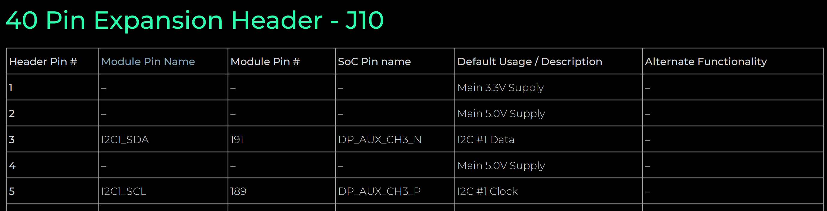
Step 3: Find the name of the Header Pin # making sure it's default usage is GPIO under the Default Usage / Description column
For example, check Header Pin 15. It's Default Usage is GPIO
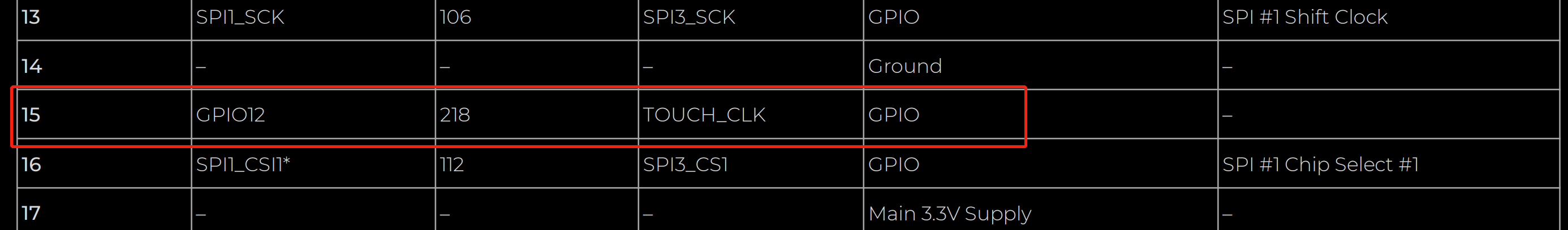
Step 4: For the same pin, find the name under Module Pin Name column. In our example, it is GPIO12
Access and Control GPIO
Now we have 2 different methods to access the GPIOs on the Jetson boards based on the availability of the GPIO labels directly. Using first method, we can directly know the GPIO pin labels after executing a command within the device. However, if the pin labels are not shown directly, you can use the second method.
Method 1
In this method, the dts file for GPIO is included inside the JetPack version you flash and will have GPIO labelled properly already so that you can obtain the pin labels directly from the device.
Step 1: Enter the terminal of the Jetson device and execute this command
sudo su
cat /sys/kernel/debug/gpio
Step 2: Find the GPIO number corresponding to the Module Pin Name that we got before
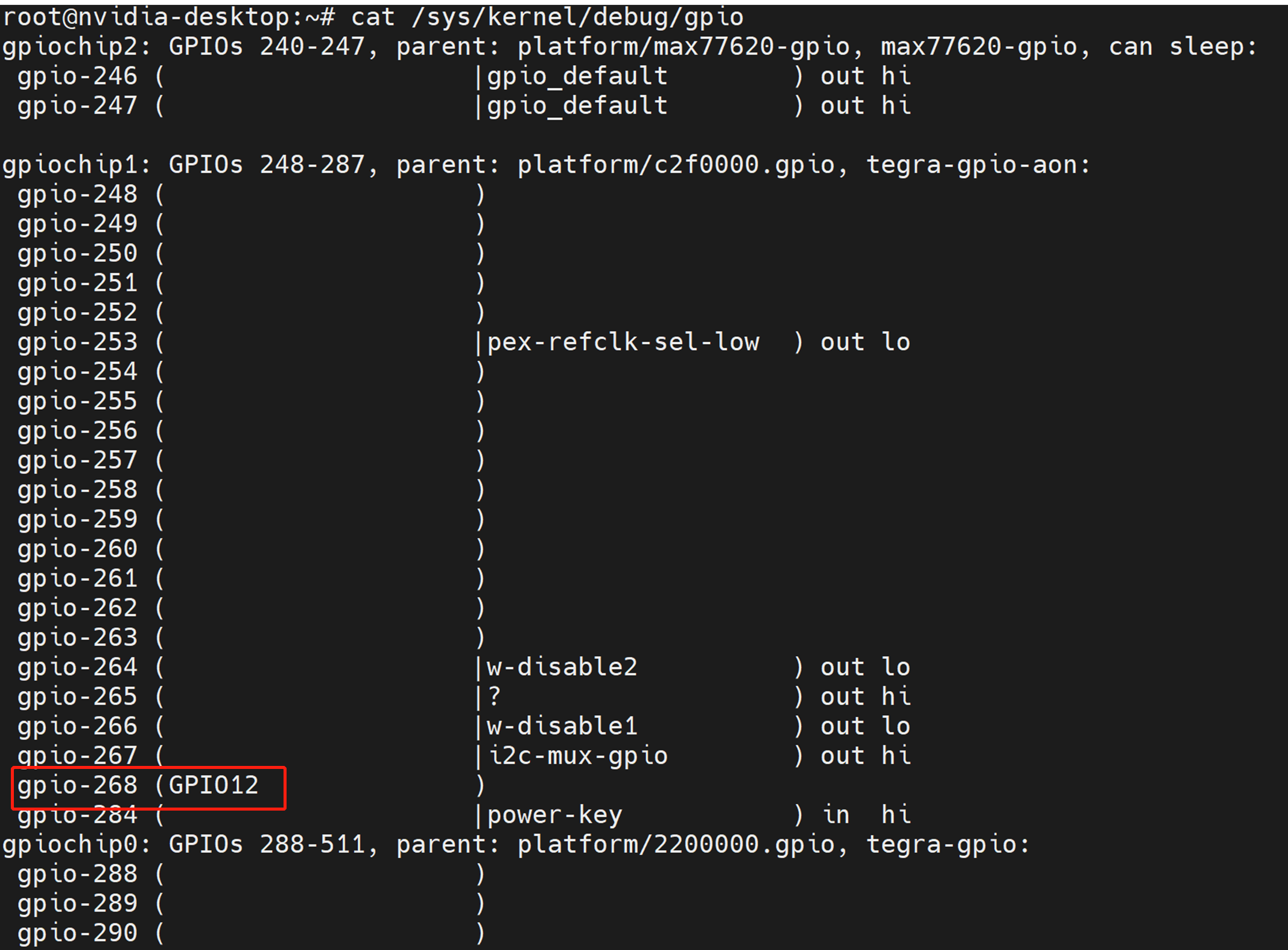
In this case, it is gpio-268 corresponding to GPIO12
Step 3: Execute the following inside the terminal to export gpio-268 pin
cd /sys/class/gpio
echo 268 > export
Step 4: Set the direction and set the value. Here direction can be in/ out and the value can be 0/ 1
For example, to set GPIO12 to HIGH
cd gpio268
echo "out" > direction
echo 1 > value
To set GPIO12 to LOW
echo 0 > value
Step 5: To set the GPIO pin that you exported back to default state, execute the following
cd ..
echo 268 > unexport
Method 2
In this method, the dts file for GPIO is in not included inside the JetPack version you flash and will not have GPIO labelled properly. So we need to refer to another document (pinmux) and obtain this pin label information. Refer the links below according to the SoM.
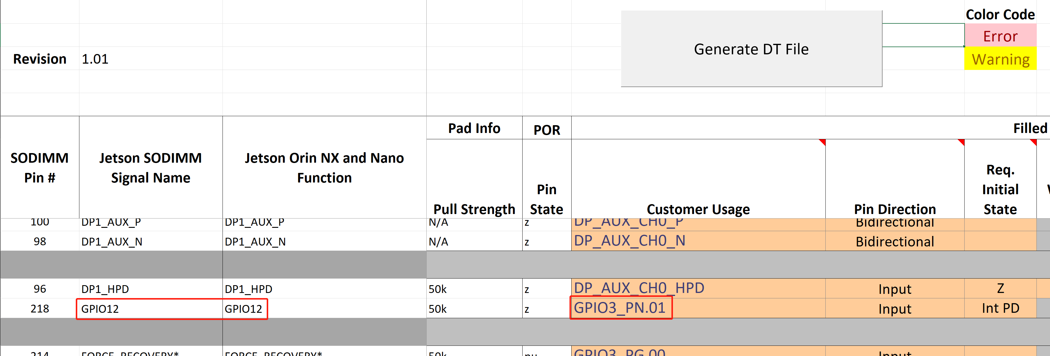
Step 1: Download the pinmux document according to the SoM you are using. Here we choose the Jetson Orin NX/ Nano document
Step 2: Find the GPIO label (under Customer Usage column) corresponding to the Module Pin Name that we got before. For example, for GPIO12, it is GPIO3_PN.01 and here we refer to PN.01
Step 3: Enter the terminal of the Jetson device and execute this command
sudo su
cat /sys/kernel/debug/gpio
Step 4: Find the GPIO number corresponding to the GPIO label that we got before
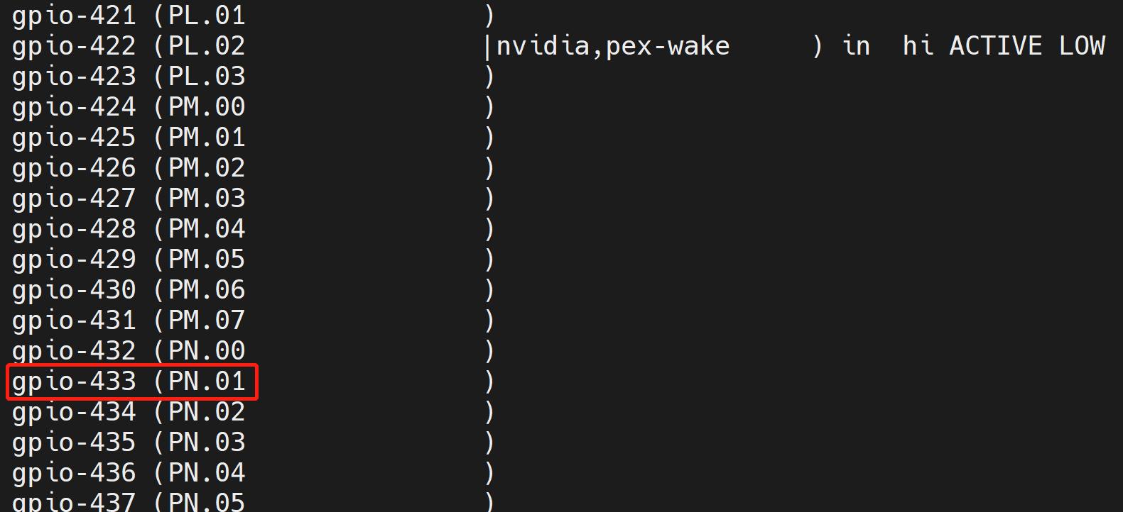
In this case, it is gpio-433 corresponding to PN.01 which is also equal to GPIO12
Step 5: Execute the following inside the terminal to export gpio-433 pin
cd /sys/class/gpio
echo 433 > export
Step 6: Set the direction and set the value. Here direction can be in/ out and the value can be 0/ 1
For example, to set GPIO12 to HIGH
cd PN.01
echo "out" > direction
echo 1 > value
To set GPIO12 to LOW
echo 0 > value
Step 7: To set the GPIO pin that you exported back to default state, execute the following
cd ..
echo 433 > unexport
For Jetpack6+
Similar to method 2, we need to refer to another document (pinmux) and obtain this pin label information. Refer the links below according to the SoM.
Step 1: Download the pinmux document according to the SoM you are using. Here we choose the Jetson Orin NX/ Nano document
Step 2: Find the GPIO label (under Customer Usage column) corresponding to the Module Pin Name that we got before. For example, for GPIO12, it is GPIO3_PN.01 and here we refer to PN.01
Step 3: Enter the terminal of the Jetson device and execute this command
sudo apt update
sudo apt install gpiod

gpioinfo
Step 4: Find the GPIO number corresponding to the GPIO label that we got before
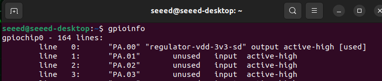
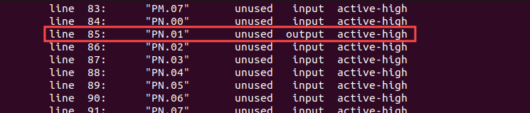
In this case, it is gpiochip0 line85 corresponding to PN.01 which is also equal to GPIO12
Step 5: Then we can use the gpioset command to configure the working mode of the GPIO.
# To set GPIO12 to HIGH
sudo gpioset --mode=wait gpiochip0 85=1
# To set GPIO12 to LOW
sudo gpioset --mode=wait gpiochip0 85=0
If you want to learn more about the gpioset command, please refer to this: https://www.acmesystems.it/gpiod
Resources
Tech Support & Product Discussion
Thank you for choosing our products! We are here to provide you with different support to ensure that your experience with our products is as smooth as possible. We offer several communication channels to cater to different preferences and needs.